Language selection

Search

Patent 2050248 Summary

Third-party information liability

Some of the information on this Web page has been provided by external sources. The Government of Canada is not responsible for the accuracy, reliability or currency of the information supplied by external sources. Users wishing to rely upon this information should consult directly with the source of the information. Content provided by external sources is not subject to official languages, privacy and accessibility requirements.

Claims and Abstract availability

Any discrepancies in the text and image of the Claims and Abstract are due to differing posting times. Text of the Claims and Abstract are posted:

  • At the time the application is open to public inspection;
  • At the time of issue of the patent (grant).
(12) Patent: (11) CA 2050248
(54) English Title: REFORMERS, PARTICULARLY AUTOTHERMIC SECONDARY REFORMERS
(54) French Title: REFORMEURS, SPECIFIQUEMENT DES REFORMEURS AUTOTHERMIQUES SECONDAIRES
Status: Term Expired - Post Grant Beyond Limit
Bibliographic Data
(51) International Patent Classification (IPC):
  • C01B 03/38 (2006.01)
  • B01J 08/02 (2006.01)
(72) Inventors :
  • SEVERIN, MANFRED (Germany)
  • MARSCH, HANS-DIETER (Germany)
(73) Owners :
  • UHDE G.M.B.H.
(71) Applicants :
  • UHDE G.M.B.H. (Germany)
(74) Agent: SMART & BIGGAR LP
(74) Associate agent:
(45) Issued: 1997-03-18
(22) Filed Date: 1991-08-29
(41) Open to Public Inspection: 1992-03-01
Examination requested: 1992-02-13
Availability of licence: N/A
Dedicated to the Public: N/A
(25) Language of filing: English

Patent Cooperation Treaty (PCT): No

(30) Application Priority Data:
Application No. Country/Territory Date
P 40 27 410.1 (Germany) 1990-08-30

Abstracts

English Abstract


A reformer, particularly an autothermic secondary
reformer, is equipped with a central gas feed pipe penetrating
the catalyst bed from the lower side and connected to a mixing
and reaction chamber. A feeding device for the oxidizing agent
is arranged at least at one level above the catalyst bed and
penetrates reaction chamber wall from the external side, the
device consisting of at least two inlet nozzles. The outlet
end of centre feed pipe is located near the level of the feeding
device for the oxidizing agent or above said level.


Claims

Note: Claims are shown in the official language in which they were submitted.

THE EMBODIMENTS OF THE INVENTION IN WHICH AN EXCLUSIVE
PROPERTY OR PRIVILEGE IS CLAIMED ARE DEFINED AS FOLLOWS:
1. A reformer, in particular an autothermal secondary
reformer, comprising a gas feed which is passed centrally from
below through the catalyst into a mixing or reaction chamber, and
an oxidation agent feed, wherein in at least one plane above the
catalyst bed are at least two feed nozzles for feeding the
oxidation agent, which pass through the internal insulation from
the outside inwardly, wherein the outlet end of the central gas
feed is disposed in the plane of the oxidation agent feed or in a
still higher plane above the plane of the oxidation agent feeds.
2. A reformer according to claim 1 wherein the feed nozzles
are aligned with the inside of the insulation.
3. A reformer according to claim 1 or claim 2 wherein there
is provided a supply conduit in ring form for supplying the feed
nozzles.
4. A reformer according to claim 1 or claim 2 wherein the
central gas feed is provided at its outlet end with a gas
distributor.
5. A reformer according to claim 1 or claim 2 wherein the
plane in which the outlet end of the gas feed is disposed and the
plane in which the feed nozzles are arranged extend parallel to
each other and perpendicularly to the vertical centre line of the

mixing and reaction chamber.
6. A reformer according to claim 4 wherein the gas
distributor is in the form of a swirl-producing element.
7. A reformer according to claim 4 wherein the gas
distributor comprises a housing whose vertical centre line
coincides with the vertical centre line of the mixing or reaction
chamber and at its outside has slit-shaped openings which are
defined by vertical guide walls.
8. A reformer according to claim 7 wherein the guide walls
are arranged symmetrically relative to the vertical centre line of
the mixing and reaction chamber and are set at an angle .delta. of less
than 90° relative to the associated radius.
9. A reformer according to claim 1 wherein the feed nozzles
are set at an angle .alpha. of between 25 and 45° relative to the
associated radius.
10. A reformer according to one of claims 1, 2, or 9 wherein
the feed nozzles are provided with a cooling device and with a
device for influencing the flame shape.
11. A reformer according to claim 10 wherein the cooling

device comprises a cooling agent flowing in a closed or open
double casing.

Description

Note: Descriptions are shown in the official language in which they were submitted.


20~0248
Reformers Particularlv autothermic secondarv reformers
The invention relates to a reformer, particularly to an autothermic secondary
reformer, equipped with a gas feed pipe arranged in the centre, penetrating the
catalyst bed from the lower side and connected to a mixing and reaction chamber,and with a feeding device for the oxidizing agent.
Patent DE-C 37 35 193 describes such a reformer which has a common feed pipe forgas and oxidizing agent, said pipes being arranged in the centre, penetrating
the catalyst bed from the lower side and communicating with the upper section ofthe reaction chamber. This unsophisticated design of a common inlet stream of
process gas and oxidizing agent, however, may cause insufficient mixing and
distribution of the two components required to optimize the reaction process in
the catalyst bed. The reactor described in
DE-A 15 42 539 is of the cross-flow type.
The aim of the invention is to design a device for an optimum distribution of
the oxidizing agent and a thorough mixing with the process gas by means of a
centre feed pipe penetrating the reactor from the lower end.
The invention provides for a reactor of the type mentioned above, with a feedingdevice arranged at one level above the catalyst bed, penetrating the reaction
chamber wall from the external side and consisting of at least two inlet
nozzles.
Said inlet nozzles are used as mixing and distributing components and permit andoptimum mixing of the reactants in the combustion chamber.
DE-A 28 41 127 describes a seondary reformer in which jet-type elements are
deployed for mixing and distributing the oxidizing agent and the process gas.
The disadvantage of this design is that the process gas is not fed via a centre
pipe through the catalyst bed into the mixing and reaction chamber, the inherentmerits of the centre pipe thus being abandoned. This applies also to the
configuration recommended in DE-A 35 32 413.

- 2 - 2 0 ~ 0 2 ~ 8
According to a further embodiment, a specific advantage is obtained by arrangingthe gas outlet of the centre feed pipe for the process gas on the level of the
oxidizing agent inlet or even higher in order to optimize gas mixing.
It is useful to place the gas feed pipe outlet and the feed nozzles in parallel
and to arranged them vertically to the vertical centre axis of the mixing and
reaction chamber.
The embodiment of the invention provides for inlet nozzles that are flush with
the internal side of the internal liner. A circular feed line may be provided
for the supply of the fluids to the inlet valves.
According to a further embodiment of the invention, a distributor is mounted to
the outlet of the ce`ntre feed pipe and - as a specific feature - it is designedas swirl inducer. This construction improves and intensifies the swirl effect inthe mixing and reaction chamber, the gas leaving the chamber at a substantially
lower temperature and forming a protective blanket around the distributor.
In this case, it is recommended that the vertical axis of the box-type gas
distributor coincide with that of the mixing and reaction chamber and that the
distributor be provided with external oblong holes flanked by vertical
deflectors.
It is of particular advantage to place the deflectors symmetrically to the
vertical axis of the mixing and reaction chamber, i.e. at an angle of <90
measured from the radius; it is also possible to arrange the axis of the inlet
nozzles at an angle of <90 measured from the radius concerned, which serves to
optimize the flow pattern. This special inlet configuration also permits a
larger space for the flame by providing an adequate coning angle. The invention
also provides for inlet nozzles that can be placed at a certain angle measured
from the position of their free ends.
It is of course possible to provide a cooler for the inlet nozzles, said cooler
having a closed or open jacket cooled by water, steam, etc.
It may also be useful to equip the inlet nozzles with a device for controlling
the flame shape.

3 2050248
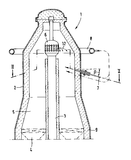
The drawings and diagrams listed below serve to illustrate the invention:
Fig. 1: cross-sect;onal view of the upper part of a
secondary reformer according to the invention
Fig. 2: cross-sectional view II-II of the device in Fig. 1.
The secondary reformer (1) shown in the figures has - inter alia - reaction
chamber 2 and gas feed pipe 3 placed in the centre, said pipe penetrating
catalyst bed 4 and communicating with mixing and reaction chamber 5.
The outlet of gas feed pipe 3 is equipped with gas distributor 6, inlet nozzles
7 for the oxidizing agent being arranged underneath the outlet end of feed pipe
3 and fed via circular feed line 3.
Fig. 2 shows feed nozzles 7 which are flush with the internal liner of reaction
chamber wall 2 and arranged at angle a measured from the vessel radius 11 and,
if required, at an angle b (Fig. 1). Gas distributor 6 has deflectors 10 which
form an angle d measured from the vessel radius 11. Arrows 12 indicate the
process gas stream and when the process gas and oxidizing agent are mixed, the
flames are ignited and burn in the manner shown in Fig. 2 (flame shape 13).
The process takes place as follows:
The process gas stream leaving the central feed pipe 6 flow in a swirl-type
manner due to deflectors 10. Said gas streams mix with the oxidizing agent fed
by means of nozzles into the mixing and reaction chamber 5 so that the reaction
gas is oxidized. The reaction product subsequently flows through the catalyst
bed.
It is of course possible to modify the embodiment of the invention described
above without abandoning the basic configuration. Thus, the invention is not
limited to the type of gas distributor described above. The deflectors may be
curved or bent and their thickness is variable. Nozzles may be installed in the
head of gas feed pipe 3 instead of the circular inlet ducts formed by the
deflectors.
B

Representative Drawing
A single figure which represents the drawing illustrating the invention.
Administrative Status

2024-08-01:As part of the Next Generation Patents (NGP) transition, the Canadian Patents Database (CPD) now contains a more detailed Event History, which replicates the Event Log of our new back-office solution.

Please note that "Inactive:" events refers to events no longer in use in our new back-office solution.

For a clearer understanding of the status of the application/patent presented on this page, the site Disclaimer , as well as the definitions for Patent , Event History , Maintenance Fee  and Payment History  should be consulted.

Event History

Description Date
Inactive: Expired (new Act pat) 2011-08-29
Grant by Issuance 1997-03-18
Application Published (Open to Public Inspection) 1992-03-01
All Requirements for Examination Determined Compliant 1992-02-13
Request for Examination Requirements Determined Compliant 1992-02-13

Abandonment History

There is no abandonment history.

Fee History

Fee Type Anniversary Year Due Date Paid Date
MF (patent, 6th anniv.) - standard 1997-08-29 1997-07-10
MF (patent, 7th anniv.) - standard 1998-08-31 1998-08-06
MF (patent, 8th anniv.) - standard 1999-08-30 1999-07-29
MF (patent, 9th anniv.) - standard 2000-08-29 2000-07-12
MF (patent, 10th anniv.) - standard 2001-08-29 2001-07-30
MF (patent, 11th anniv.) - standard 2002-08-29 2002-07-18
MF (patent, 12th anniv.) - standard 2003-08-29 2003-07-24
MF (patent, 13th anniv.) - standard 2004-08-30 2004-07-23
MF (patent, 14th anniv.) - standard 2005-08-29 2005-07-27
MF (patent, 15th anniv.) - standard 2006-08-29 2006-07-25
MF (patent, 16th anniv.) - standard 2007-08-29 2007-07-23
MF (patent, 17th anniv.) - standard 2008-08-29 2008-07-24
MF (patent, 18th anniv.) - standard 2009-08-31 2009-08-13
MF (patent, 19th anniv.) - standard 2010-08-30 2010-08-12
Owners on Record

Note: Records showing the ownership history in alphabetical order.

Current Owners on Record
UHDE G.M.B.H.
Past Owners on Record
HANS-DIETER MARSCH
MANFRED SEVERIN
Past Owners that do not appear in the "Owners on Record" listing will appear in other documentation within the application.
Documents

To view selected files, please enter reCAPTCHA code :


To view images, click a link in the Document Description column. To download the documents, select one or more checkboxes in the first column and then click the "Download Selected in PDF format (Zip Archive)" or the "Download Selected as Single PDF" button.

List of published and non-published patent-specific documents on the CPD .

If you have any difficulty accessing content, you can call the Client Service Centre at 1-866-997-1936 or send them an e-mail at CIPO Client Service Centre.


Document
Description 
Date
(yyyy-mm-dd) 
Number of pages   Size of Image (KB) 
Description 1993-11-19 3 126
Claims 1993-11-19 2 65
Drawings 1993-11-19 2 51
Description 1997-02-25 3 132
Claims 1997-02-25 3 65
Drawings 1997-02-25 2 49
Abstract 1997-02-25 1 17
Abstract 1993-11-19 1 17
Representative drawing 1999-08-04 1 17
Fees 1996-07-11 1 49
Fees 1995-07-12 1 43
Fees 1994-07-25 1 51
Fees 1993-07-19 1 24
Examiner Requisition 1994-05-08 2 75
Prosecution correspondence 1994-07-12 1 23
Examiner Requisition 1996-03-04 2 74
Prosecution correspondence 1996-05-27 2 59
PCT Correspondence 1996-12-18 1 30
Courtesy - Office Letter 1992-05-24 1 38
Prosecution correspondence 1992-02-12 1 32
Prosecution correspondence 1991-10-17 1 36