Language selection

Search

Patent 2050487 Summary

Third-party information liability

Some of the information on this Web page has been provided by external sources. The Government of Canada is not responsible for the accuracy, reliability or currency of the information supplied by external sources. Users wishing to rely upon this information should consult directly with the source of the information. Content provided by external sources is not subject to official languages, privacy and accessibility requirements.

Claims and Abstract availability

Any discrepancies in the text and image of the Claims and Abstract are due to differing posting times. Text of the Claims and Abstract are posted:

  • At the time the application is open to public inspection;
  • At the time of issue of the patent (grant).
(12) Patent: (11) CA 2050487
(54) English Title: INJECTION DEVICE FOR THE ON-LINE WET CLEANING OF COMPRESSORS
(54) French Title: DISPOSITIF D'INJECTION POUR LE LAVAGE DE COMPRESSEURS EN MARCHE
Status: Term Expired - Post Grant Beyond Limit
Bibliographic Data
(51) International Patent Classification (IPC):
  • F04D 29/70 (2006.01)
(72) Inventors :
  • KOLEV, SEJKO (Switzerland)
  • ROBBEN, RUDOLF (Switzerland)
(73) Owners :
  • TURBOTECT AG
(71) Applicants :
  • TURBOTECT AG (Switzerland)
(74) Agent: NORTON ROSE FULBRIGHT CANADA LLP/S.E.N.C.R.L., S.R.L.
(74) Associate agent:
(45) Issued: 2001-10-02
(86) PCT Filing Date: 1991-02-08
(87) Open to Public Inspection: 1991-08-22
Examination requested: 1997-11-26
Availability of licence: N/A
Dedicated to the Public: N/A
(25) Language of filing: English

Patent Cooperation Treaty (PCT): Yes
(86) PCT Filing Number: PCT/CH1991/000035
(87) International Publication Number: WO 1991012433
(85) National Entry: 1991-10-11

(30) Application Priority Data:
Application No. Country/Territory Date
480/90-3 (Switzerland) 1990-02-14

Abstracts

English Abstract


In an injection device for the ON-LINE wet
cleaning of compressors, the liquid cleaning agent is
injected via a nozzle into the flow passage upstream of
the compressor. The nozzle is a molecular atomizer which
is mounted in the casing wall of the compressor in such
a way that it can be adjusted in a three-dimensional
manner in a ball-and-socket joint and can be maintained,
adjusted or even exchanged during the operation of the
machine.


Claims

Note: Claims are shown in the official language in which they were submitted.

CLAIMS:
1. An injection device for on-line wet cleaning of
compressors, comprising:
nozzle means for directing a liquid cleaning agent
onto a flow passage located upstream of a compressor inlet,
the compressor comprising a casing wall; and
ball joint means movably mounted in the casing
wall of the compressor, said nozzle means being an atomizing
nozzle which is mounted in said ball joint means, said ball
joint means being adjustable in a three dimensional manner
for permitting said atomizing nozzle mounted therein to be
adjustable in said three-dimensional manner.

Description

Note: Descriptions are shown in the official language in which they were submitted.


,
- 1 -
TITLE OF THE INVENTION
Infection device for the ON-LINE wet cleanincx of
compressors
BACRGROUND OF THE INVENTION
Field of the Invention
The invention relates to an injection device for
the ON-LINE wet cleaning of compressors, by means of
which injection device the liquid cleaning agent can be
directed via a nozzle into the flow passage upstream of
the compressor.
Discussion of Background
The injection devices used hitherto offer too
little protection against possible consequential damage
to the blades. As a rule these injection devices are
rebound nozzles whose connecting pieces necessarily
project relatively deep into the flow passage. In
particular in transonic compressors, such disturbing
elements in the compressor inlet are inadmissible for
technical reasons related to flow. Potential risks with
regard to blade damage are of a two-fold nature: on the
one hand, the connecting pieces can be shaken off in the
event of resonance and be flung against the blading; on
the other hand, the connecting pieces can fly out of
their anchorage as a result of corrosion damage, for
example pitting. The operating mode of rebound nozzles of
this type is also not quite satisfactory. The atomizing
of the cleaning liquid is not uniform at different drop
sizes. This can lead to the partial inducement of
vibrations at the blading. Furthermore, there is the
possibility of erosion of the blade coating. In addition,
the nozzle output can be set only by pressure change, in
the course of which, however, the drop size is directly
affected. Finally, the direction of the nozzle jet can
also only be varied around the connecting-piece axis
itself, which makes it impossible to individually adapt
the nozzle jet to the prevailing flow conditions.
SUMMARY OF THE INVENTION
Accordingly, one object of the invention is to
provide a novel device of the type mentioned at the

X054 ~~7
- 2 -
beginning which on the one hand is adjustable in spray
output and spray direction and on the other hand provides
maximum protection for the compressor blading against parts
of the device detached by force.
According to the invention, this is achieved in
that the nozzle is a molecular atomizer which is mounted in
the casing wall of the compressor in such a way that it can
be adjusted in a three-dimensional manner in a ball-and-
socket joint.
According to a further broad aspect of the
present invention there is provided an injection device for
ON-LINE wet cleaning of compressors. The device comprises
nozzle means for directing a liquid cleaning agent onto a
flow passage located upstream of a compressor inlet. The
compressor comprises a casing wall. Ball joint means is
movably mounted in the casing wall of the compressor. The
nozzle means is a molecular atomizer which is mounted in
the ball joint means. The ball joint means is adjustable
in a three dimensional manner for permitting the nozzle
means mounted therein to be adjustable in the three-
dimensional manner.
The advantage of the invention can be seen in
particular from the fact that, on account of the
commercially available nozzle used in a universal insert,
output corrections as well as adjustments to the direction
of the nozzle jet and the type of nozzle jet can be carried
out when the compressor is running without impairing the
operation of the machine.
BRIEF DESCRIPTION OF THE DRAWINGS
A more complete appreciation of the invention and
many of the attendant advantages thereof will be readily
obtained as the same becomes better understood by reference
to the following detailed description when considered in
connection with the accompanying drawings, wherein:

2a
Fig. 1 shows a schematic longitudinal section
through the inlet portion of an axial
compressor;
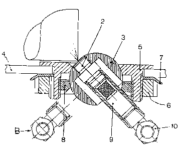
Fig. 2 shows a sectional representation of the
mounted adjustable injection device.
Parts of the compressor which are not essential
to the invention have been omitted. The flow directions of
the operating media are designated by arrows.
DESCRIPTION OF THE PREFERRED EMBODIMENTS
Referring now to the drawings, wherein like
reference numerals designate identical or corresponding
parts throughout the several views, in Fig. 1, four
installation examples for the injection nozzles are shown.
It goes without saying that, irrespective of the
configuration of the compressor inlet selected, the
positions and number of nozzles are to be selected in
such a way that on the one hand they act on the entire
A

- 3 -
through-flow cross-section and on the other hand they are
accessible from outside. The medium to be injected is as
a rule a mixture of a commercially available concentrate
and prepared water.
According to Fig. 2, this mixture is injected
into the through-flow passage 1 via a molecular atomizer
2. This atomizer 2 is fastened in the interior of a ball-
and-socket joint 3 by means of a screw thread in such a
way that the nozzle orifice is at least approximately
flush with the ball surface. In the case shown, the spray
cone has an angle of about 90°. This means that the
longitudinal axis of the atomizer only has to be set at
45° to the flow-limiting wall 4 of the compressor casing
in order to cover the wall zones.
This case shown applies, for example, to an
injection form in which the mixture is injected in the
flow direction of the air flowing into the compressor.
If, however, the mixture is to be injected against the
flow direction of the fresh air drawn in, the ball-and-
socket joint merely has to be swung round through 90°
into the position designated by B.
In order to make these and other adjustments
during the operation of the machine, the ball-and-socket
joint 3 lies in a joint shell which is made in a casing
5. This casing of preferably cylindrical form, which
passes through the compressor wall 2 (sic), lies with a
flange-like base on the inside of the compressor wall.
The said joint shell is arranged in this base. The
cylindrical part of the casing 5 projecting on the
outside of the compressor wall is provided with both an
internal thread and an external thread. Via the latter,
the casing is firmly screwed to the wall 2 ( sic ) by means
of shaft nut 6 and lock washer ?. Via the internal
thread, the ball-and-socket joint 3 is pressed by means
of a clamping nut 8 into the joint shell and held firmly
in the respective position.
The molecular atomizer 2 is connected to a feed
tube 9 which carries a union piece 10 at its other end
for receiving a, for example flexible, hose connection 11

~.~'
- 4 -
(Fig. 1). The diameter of the feed tube and the axial
length of the cylindrical part of the casing 4 (sic) are
matched to one another in such a way that the feed tube
9 can readily perform a swivel movement through 90°, and
in fact in both the drawing plane and perpendicularly
thereto. Consequently, no limits are imposed on the
adjustability of the spray angle.
It can be recognized from Fig. 2 that the parts
projecting into the through-flow compressor passage are
reduced to an absolute minimum. Due to the design, it is
also not possible for parts detached from the device to
pass into the blading. In addition, there is hardly any
risk with regard to parts possibly being shaken off or
with regard to corrosion damage to the device. For those
parts of the device that are in contact with the cleaning
agent are of course produced from stainless materials.
The novel device is distinguished by the fact
that it is extremely easy to maintain. Thus all service
work such as cleaning, adjusting, inspecting and repair
ing can be carried out when the machine is running. This
also applies of course to the actual exchange of the
molecular atomizer in the event of a requisite change to
its output or the shape of the nozzle jet. It has been
found that it takes about 15 minutes to exchange a nozzle
unit.
Obviously, numerous modifications and variations
of the present invention are possible in light of the
above teachings. It is therefore to be understood that
within the scope of the appended claims, the invention
may be practiced otherwise than as specifically described
herein.

Representative Drawing
A single figure which represents the drawing illustrating the invention.
Administrative Status

2024-08-01:As part of the Next Generation Patents (NGP) transition, the Canadian Patents Database (CPD) now contains a more detailed Event History, which replicates the Event Log of our new back-office solution.

Please note that "Inactive:" events refers to events no longer in use in our new back-office solution.

For a clearer understanding of the status of the application/patent presented on this page, the site Disclaimer , as well as the definitions for Patent , Event History , Maintenance Fee  and Payment History  should be consulted.

Event History

Description Date
Inactive: Expired (new Act pat) 2011-02-08
Grant by Issuance 2001-10-02
Inactive: Cover page published 2001-10-01
Inactive: Final fee received 2001-06-13
Pre-grant 2001-06-13
Notice of Allowance is Issued 2000-12-19
Letter Sent 2000-12-19
Notice of Allowance is Issued 2000-12-19
Inactive: Approved for allowance (AFA) 2000-12-01
Amendment Received - Voluntary Amendment 2000-10-31
Inactive: S.30(2) Rules - Examiner requisition 2000-05-03
Inactive: Application prosecuted on TS as of Log entry date 1997-12-19
Inactive: RFE acknowledged - Prior art enquiry 1997-12-19
Inactive: Status info is complete as of Log entry date 1997-12-19
All Requirements for Examination Determined Compliant 1997-11-26
Request for Examination Requirements Determined Compliant 1997-11-26
Application Published (Open to Public Inspection) 1991-08-22

Abandonment History

There is no abandonment history.

Maintenance Fee

The last payment was received on 2001-01-25

Note : If the full payment has not been received on or before the date indicated, a further fee may be required which may be one of the following

  • the reinstatement fee;
  • the late payment fee; or
  • additional fee to reverse deemed expiry.

Please refer to the CIPO Patent Fees web page to see all current fee amounts.

Owners on Record

Note: Records showing the ownership history in alphabetical order.

Current Owners on Record
TURBOTECT AG
Past Owners on Record
RUDOLF ROBBEN
SEJKO KOLEV
Past Owners that do not appear in the "Owners on Record" listing will appear in other documentation within the application.
Documents

To view selected files, please enter reCAPTCHA code :


To view images, click a link in the Document Description column. To download the documents, select one or more checkboxes in the first column and then click the "Download Selected in PDF format (Zip Archive)" or the "Download Selected as Single PDF" button.

List of published and non-published patent-specific documents on the CPD .

If you have any difficulty accessing content, you can call the Client Service Centre at 1-866-997-1936 or send them an e-mail at CIPO Client Service Centre.


Document
Description 
Date
(yyyy-mm-dd) 
Number of pages   Size of Image (KB) 
Abstract 1994-02-26 1 12
Claims 1994-02-26 1 12
Drawings 1994-02-26 1 32
Description 1994-02-26 4 166
Description 1998-02-02 5 209
Claims 1998-02-02 1 15
Cover Page 1994-02-26 1 12
Cover Page 2001-09-20 1 46
Claims 2000-10-31 1 17
Representative drawing 2001-09-20 1 15
Representative drawing 1999-09-24 1 17
Reminder - Request for Examination 1997-10-08 1 117
Acknowledgement of Request for Examination 1997-12-19 1 173
Commissioner's Notice - Application Found Allowable 2000-12-19 1 165
PCT 1991-10-11 15 491
Correspondence 2001-06-13 1 64
Fees 1997-01-22 1 55
Fees 1996-01-31 1 57
Fees 1993-01-18 1 38
Fees 1995-02-01 1 56
Fees 1994-01-19 1 42