Note: Descriptions are shown in the official language in which they were submitted.
2~5~
CONTROL SY8TEN
Fiela of the Invention
The instant invention relates to control of factory or
other operations including process or machine control systems, and
more particularly, to methods and devices for facilitating ease of
operator interaction with process control computer programs.
Ba~kground of the Invention
It is known that many factory and other workers have
difficulty in adapting to the use of computer controlled systems
within the work environment. An example of this problem occurs in
the area of control systems. Here, in previous systems, not
employing computers, the factory worker operated the factory
control system via three-dimensional manual controls on control
panels and viewed information on information display areas of the
control panel. The factory worker manipulated these manual
controls, such as levers, knobs, toggle switches, and push buttons,
etc., by hand.
Presently, in computerized control systems, the factory
worker is requested to provide the same information and adjustments
as with the manual control panel. However, in computerized systems
the factory worker provides that information via computer program
activated prompts rather than the manual manipulation of the
control panel. Unfortunately, unskilled personnel with limited
previous experience related to computers have difficulty adapting
to this change in the provision of information.
This problem is avoided in present systems by
incorporating the mechanical devices into the computerized control
0 ~ ~ 7
system. For example in U.S. Patent No.( ~ 697,2 ~ to Boytor et al,
a machine control system is disclosed having a CRT on which is
provided information relating to the control and programming of
push buttons, selector switches, potentiometers, and the like
(Column 3, lines 38-52; Column 7, lines 50-53). However, the push
buttons and switches are not graphic displays on the CRT, but
rather, manual mechanical devices as have been used in control
systems for many years. A further example of such a system where
manual, mechanical control panel devices are used in computer
process control systems is seen in U.S. Patent No ~ 821,03 ~ to
Batson et al. Thus, these systems retain the drawbacks of previous
non-computerized process control systems such as added expense,
maintenance, and likelihood of error.
Thus, present process control systems have not fully
integrated the process control operations with computer technology.
The inability of the factory worker to adapt to such technology is
an impediment to such integration.
8ummary of the Invention
These and other objects of the present invention are
provided in a control system by which an operator controls
equipment by selectively changing the operation condition thereof
and which facilitates interaction between the control system and
the operator. The control system comprises a device for receiving
at least one input signal from the equipment being controlled which
is a function of at least one operating condition thereof. The
system also includes a touch sensitive display screen for
2 ~ 7
representing the control system to the operator and at least one
object represented on said touch sensitive display screen for
displaying the at least one operating condition in response to
receipt of the input signal. The object is a graphic
representation of a mechanical control device used on control
panels and, thus, is a familiar sight to the unskilled worker, who
is typically ill at ease with computers. Devices for manipulating
the object are also included and cause a change in the value
thereof on the display screen to indicate a change in the operation
condition. The manipulation devices are also graphic
representations of control devices from control panels which also
facilitates worker interaction with the system. The system also
includes a device for generating an output signal to be transmitted
to the equipment which is a function of the change in value of the
object caused by the manipulation device.
The object may be manipulated in a similar manner as the
operator would manipulate the mechanical control device of the
control panel to effect a change in the operation condition.
A control svstem method is also disclosed which allows
an operator to control equipment by selectively changing the
operation conditions thereof and for facilitating interaction
between a control system and the operator of the system by
providing a touch sensitive display screen for representing the
control system to the operator and for receiving input signals from
the equipment, where the signal is a function of at least one
operating condition thereof. The method also supplies at least one
2~:S~ 7
object on the touch sensitive display screen for displaying at
least one operating condition. The object is a graphic
representation resembling mechanical devices used on control
panels. The at least one object is manipulated by touching the
display screen to effect a response in the operating condition of
the equipment. The manipulation of the object may comprise the
touching of the display screen at the point where the object
appears and in moving the touching along the display screen to
accomplish manipulation of the object.
rief Description of the Drawing~
Figure 1 is a view of a main screen of a process control
program in accordance with an embodiment of the present invention;
Figure 2 is yet another view of a screen of a process
control program bearing graphic representations resembling a
control panel in accordance with an embodiment of the present
invention;
Figure 3 is yet another view of a screen of a process
control program bearing graphic representations resembling a
control panel in accordance with an embodiment of the present
invention;
Figure 4 is yet another view of a screen of a process
control program bearing graphic representations resembling a
control panel in accordance with an embodiment of the present
invention;
Figure 5 is yet another view of a screen of a process
control program bearing graphic representations resembling a
2~ 3~5~
control panel in accordance with an embodiment of the present
nventlon;
Figure 6 is yet another view of a screen of a process
control program bearing graphic representations resembling a
control panel in accordance with an embodiment of the present
nvention;
Figure 7 is yet another view of a screen of a process
control program bearing graphic representations resembling a
control panel in accordance with an embodiment of the present
invention;
Figure 8 is yet another view of a screen of a process
control program bearing graphic representations resembling a
control panel in accordance with an embodiment of the present
invention;
Figure 9 is yet another view of a screen of a process
control program bearing graphic representations resembling a
control panel in accordance with an embodiment of the present
invention;
Figure 10 is yet another view of a screen of a process
control program bearing graphic representations resembling a
control panel in accordance with an embodiment of the present
invention;
Figure ll is yet another view of a screen of a process
control program bearing graphic representations resembling a
control panel in accordance with an embodiment of the present
invention;
2 ~ 7
Figure 12 is a detailed block diagram of the electrical
circuits of the process control program of Figures 1-11;
Figure 13 is a detailed block diagram of the input/output
interface and modules receiving input data from the system being
controlled; and
Figure 14 is a flow chart showing one application of the
computer terminal of the present invention for the generation of
appropriate ASCII codes to control one of the graphic
representations viewed on the computer terminal.
Description of the Preferred Embodiment
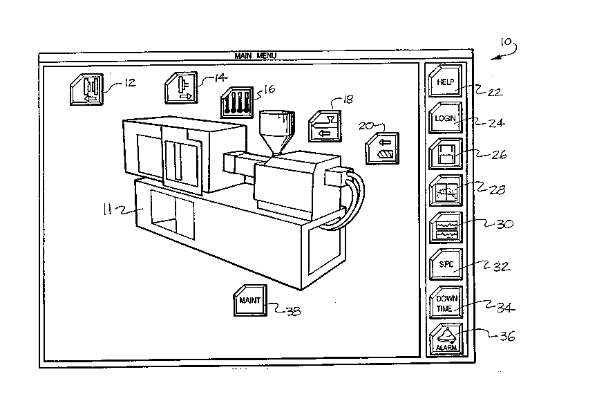
Referring now to the drawings, Figure 1 is an
illustration of the initial screen or main menu 10 of a preferred
embodiment of the present invention. This embodiment is a process
control system for controlling the processes related to plastic
injection molding machinery. As is obvious to those of skill in
the art, the instant invention is not limited to plastic injection
mold systems, but, rather, may be used in virtually any type of
control system.
A graphic representation of the plastic injection molding
machine 11 is shown at the center of main menu lO. The graphic
representation of the plastic injection molding machine 11 is
preferably close to photographic quality in order to orient and
familiarize the factory worker operator with the process control
system and to correlate the control system to the machinery. The
screen is viewed on a touch sensitive display screen to allow for
easy operator interaction with the system. The main menu 10 also
2~t`i~
contains push button objects or touch targets which, when selected
(i.e., touched), cause the control system to change screens from
the main menu 10 to other process control screens relating to
specific aspects of the process control of the plastic mold
injection system and allowing the operator to adjust various
parameters of the system being controlled.
For example, in this preferred embodiment of a plastic
mold injection system, the following push buttons are employed on
the main menu: push button 12 accesses the screen for setting up
the opening of the clamp unit or mold, push button 14 allows for
the setup of the ejector which displaces the molded part out of the
mold, push button 16 allows for the setup of the various
temperatures required during each phase of the plastic mold
injection process, push button 18 allows for the setup of the
nozzle for injection of the plastic, push button 20 establishes the
parameters for the hydraulic ram as it pushes the plastic material
into the mold, push button 24 accesses a data-gathering screen for
the provision of information such as which factory worker is
working with the system, timing and security clearances (for
example, there may be different levels of security allowing various
factory workers to access various levels of the system), push
button 26 allows for the operator to request certain data upon the
occurrence of certain events, push button 28 accesses real time
profiles of process variables within the plastic mold injection
system, push button 30 access SPC information (Statistical Process
~ g~
Control). The SPC information screen displays statistical analysis
of the process, distribution curves, and trend charts, etc.
Push button 32 accesses a screen which allows for the
placement of tolerances on the various processes within a plastic
mold injection system, push button 34 accesses a screen wherein an
operator can provide information relating to a machine breakdown
and optionally track the length of time of the breakdown, push
button 36 is the alarm push button which allows the operator to
access a screen which provides information relating to a machine
breakdown, and push button 38 allows the factory worker operator
to access various types of status information for troubleshooting
purposes.
Referring now to Figure 2, the screen accessed by
injection push button 20 of Figure 1 is shown. In Figure 2,
various control device objects are represented which establish the
parameters for the injection of plastic into a mold. By adjusting
these objects, the injection process parameters of the equipment
are changed or controlled. These control device objects resemble
various mechanical devices on control panels. Additionally in
Figure 2, a bar graph object 43 graphically displays the various
parameters of the injection process such as would be seen on a
typical control panel. Figure 2 shows various calibrated scales
40, 42, and 46 which represent respectively the speed at which the
injection ram moves between various positions, the position of the
ram at the various steps of the injection cycle, and the pressure
with which the injection ram is operating. The objects shown in
2 ~
Figure 2 are very similar to what a factory worker would see on a
conventional control panel and, consequently, the worker is more
familiar and at ease with a representation such as Figure 2 than
with a typical computer prompt seen in most process control
systems.
The scales 40, 42, and 46 increase or decrease the
parameter's value by the operator touching the slider buttons 40A,
42A, and 46A and then moving the operator's finger along the
calibrations included in each scale. The control system causes the
slider button to move along with the operator's finger and remain
where the operator's last movement occurred. When the operator has
correctly changed a parameter (speed, position, or pressure), the
operator presses the "yes" button 45. This changes the prior
status of the parameter to the new value.
Upon activating the "yes" button 45, an output control
signal is sent to the equipment and the information logged into the
system is reflected by a proportional change in the bar graph 43.
For example, if the pressure slide 46A is increased, line 48 of
bar graph 43 moves in an upward direction to indicate pressure
throughout the injection process. If the position slider 42A for
step 4 i5 altered, the width of the fourth bar from the left 44 in
bar graph 43 is altered accordingly. Finally, if the speed is
changed by movement of slider 40A and a particular bar 44 of graph
43 is selected, the height of that bar 44 is altered. Particular
bars 44 may be selected for adjustment by touching the bar desired
or, for narrow bars, via cursors 49 also seen in the bottom of
Figure 2. Fine tuning of the desired increase or decrease the
sliders is possible via push buttons 47 seen in the lower portion
of Figure 2.
The buttons on the far right-hand side of Figure 2 allow
the operator to access other screens relating to the injection mold
process. For example, push button 52 accesses a screen shown in
Figure 3 which controls how long and under what pressure the
plastic material is held until it freezes. Once again calibrated
scales 52 and 54 are shown. Additionally, a bar graph 58
indicating the time, speed, and pressure of the hold pattern can
also be seen at the center of Figure 3. The scales and bar graphs
of Figure 3 may be manipulated in the same manner as the scales and
bar graphs of Figure 2. A new object is also seen in Figure 3.
This object is the dial timer 60 showing the overall hold time of
the plastic in the mold. The timer may be altered by touching and
use of push buttons 47 as with Figure 2. Note the resemblance of
the graphic dial indicator to an actual dial indicator on a
conventional control panel. This similarity is achieved through
details such as thumbwheels 61 seen to the right-hand side of each
digit. In this instance, the thumbwheels are not touch targets
(i.e., they cannot be used to alter the digits).
Referring now to Figures 1 and 4, the temperature push
button 16 of Figure 1 accesses a screen shown in Figure 4
indicating the various temperatures at various points within the
plastic mold injection system. The four objects 58 display various
temperature information including actual temperature of the zone
in the boxes 55 below thermometers 57. Arrows 62, 63, and 64
indicate the maximum, set and minimum possible temperatures for
each zone on the thermometers 57. The maximum, set and minimum
temperatures are set by touching rectangles 56 within area 58 for
each area. A temperature set screen is then accessed (see
discussion regarding Figure 5). Buttons 62A, 63A, 64A, and 65
are view-only buttons for the individual zones. As with the
previous screens, the screen of Figure 4 closely resembles a
mechanical control panel with which a typical worker is familiar.
Thus, operator interaction with the contro] system is
facilitated.
The temperatures of Figure 4 are changed in the following
manner. Referring now to Figure 5, this screen relates to the
barrel temperature and is accessed through the screen shown in
figure 4 by touching rectangles 56 above thermometers 57 in the
area 58 labeled "BARREL TEMPERATURES 1-4". The other areas 58
are accessed in a similar manner. To adjust the temperature for
a particular zone, the operator merely touches one of the buttons
68 for each zone. A slider device 70 then appears before the
thermometer 65. The operator touches the slider and moves his
finger until the slider is at the desired value. As in the
previous figures, the temperature may be fine-tuned via
incremental and decremental push buttons 47 in the lower part of
the screen. Once an acceptable change has been made, the changes
are logged into the system via the "yes" button push button 45
also in the lower portion of Figure 5 and an output temperature
control signal is sent to the equipment. The selected button 68
and the thermometer arrow 69 then display the new value.
2 ~ 5 ~
The thermometer objects 65 of Figure 5 are structured
like thermometers 57 of Figure 4 so that the interior area of the
thermometer is filled with color or shaded to the level
representing the actual temperature in each zone. The exact
temperature reading is then indicated in the window 66 dir~ctly
beneath each thermometer as in Figure 4. The maximum, minimum,
set, and preheat temperatures are shown to the side of each
thermometer 65 in windows 68. Arrows 69 indicate the point on the
thermometer for each of these particular temperatures.
Also shown in Figure 5 are objects 67 representing toggle
switches. The toggle switches are moved from one position to
another by touching the center area of the toggle switch 70. For
example, with the toggle switch 67 of zone 1, to move the toggle
switch to the preheat position, one touch is required and to move
the toggle switch to the proheat position two touches are
necessary. The proheat temperature is the production heat or set
value as seen in Figures 4 and 5. While actual control panel
toggle switches are operated by a touching and turning motion and
the graphic toggle switches of the instant invention are operated
by a touching motion only, Applicants have found that the
operations are still so similar so as not to cause operator
confusion. In the instant example of a plastic mold injection
system, toggle switches 67 are used in Figure 5 to raise the
temperature in a particular zone from the preheat status once
proheat is selected, thereby allowing production to begin in that
zone or to raise the temperature from an off condition to a preheat
condition.
Referring now to Figure 6, this screen is accessed
through the main menu of Figure 1 via a push button 14. Figure 6
shows the screen for the setup of the ejector which displaces the
molded part from the mold after the setting of the part. A number
of different objects are shown in Figure 6. For example, toggle
switch 72 allows for the turning on and off of the ejector setup
portion of the control system. Additionally, calibrated scales 74
and 84 define the position of the mold. When the mold travels to
that position, ejection of the part starts. Ejection occurs either
by a mechanical or hydraulic system (related to scale 74) or by an
air blow system (related to scale 84). Digital timers 76 and 80
show the elapsed time for the ejector return delay and air blow
time, respectively. Digital counter 78 counts the number of times
the ejector is activated. Once again, the digital timers and
counter show graphic representations of some thumbwheels 77, 79,
and 81 to the right of each digit in order to facilitate the
factory wor~er's interaction with the system. Additionally,
another toggle switch 82 is shown in the lower left-hand portion
of Figure 6.
The toggle switches are operated as indicated with
respect to Figure 5 in that the operator need only touch the
circular switch area to move it from one position to the other.
The two calibrated scales 74 and 84 may have their value changed
by touching the slider buttons 74A and 84A and dragging the finger
to the right or left to increase or decrease the value as one would
do with a mechanical slider on an actual control panel. The dial
timers and counter 76, 78, and ~o may be adjusted by pressing the
area of the timers and then using the incremental and decremental
push buttons 47 to change the time. Once any such changes have
been logged into the system via the "yes" button 45, an output
control signal is sent to the equipment. Additionally, the screen
of Figure 6 shows the actual lapsed time for each parameter of the
ejector program in windows 85, 86, and 87.
Referring now to Figure 7, another type object 89 is
shown. This object represents an LED-type readout from a control
panel. Once again, such an object facilitates the factory worker's
use of computerized process control systems. Figure 7 is accessed
via the main menu of Figure 1 through maintenance button 38.
Figure 7 may represent the actual condition of digital or analog
inputs or outputs of the plastic mold injection system and is used
for troubleshooting the system. In this example of Figure 7,
digital inputs are represented. For example, if the system breaks
down or is operating improperly, the factory worker can access
Figure 7 and check the status of various inputs to the system. The
status of the various parameters such as mold closing 90, mold
opening 91, and carriage forward 92 are indicated via LED-
resembling objects 90A, 91A, and 92A. In this embodiment, if the
specific input is sensed by the system, the objects representing
the LEDs are colored or shaded, and if they are not, the objects'
2'~
interior is left blank. Thus, the factory worker recognizes
whether the breakdown is a result of a faulty input.
Referring now to Figure 8, other objects bearing
resemblance to a mechanical control panel are shown These objects
are dial gauges 100, 102, and 104 representing, respectively, clamp
pressure, clamp speed, and clamp time. Figure 8 is accessed via
the main menu of Figure 1 by pressing push button 12 resulting in
the appearance of the screen for setting up the opening of the
clamp which then accesses a clamp screen having a push button
indicating actual value. When the operator accesses the actual
value push button by touching it, the screen of Figure 8 is brought
up. Figure 8 shows, via dial gauges 100, 102, and 104, the actual
status of certain aspects of the plastic mold injection system.
As with a typical dial gauges found on mechanical control panels,
the face of the dial gauge indicates the value for that particular
gauge. Consequently, the factory worker operator is further
familiarized with the process control system. The calibrated scale
object 105 of Figure 8 shows the actual position of the clamp via
a horizontally moving needle indicator 105A.
Referring now to Figure 9, an oscilloscope-like object
106 is shown. This screen is accessed from the main menu of Figure
1 via push button 28. Four graph profiles 107, 108, 109, and 110
are seen representing, respectively, hydraulic pressures, screw
speed, cavity pressure, and the screw position. The profile graphs
relate to the actual value sampled at fast sample rates. The
limits of the graph may be altered by touching and sliding buttons
2 ~ ~ ~ ~ 5 7
113 and 114. Button 113 adjusts the y or unit value and button
114 adjusts the time base. The cross hairs 112 shown in the middle
of the oscilloscope can be used for displaying the actual value of
the profile where it intersects the graph and may be adjusted by
5 touching slider button 115 and sliding the button to the desired
point.
Another type object resembling mechanical control panels
is shown in Figure 10. This object 125 represents a text list.
The screen of Figure 10 is accessed from the main menu's alarm push
10 button 36. The factory worker operator can scroll through the text
list by touching the incremental and decremental buttons 120 in the
lower portion of the screen and thereby highlighting each text
listing as the operator scrolls through the list. Additionally,
the operator can clear alarms by highlighting the alarm description
122 with push buttons 120 or by touching the highlighted text
portion 123 and moving the highlighted bar to the desired text
portion, and pressing the "clear this alarm button" 124.
Referring more specifically now to Figure 11, a screen
for providing information to the process control system for
20 instructing the system where to log data is shown. This screen is
accessed via the main menu of Figure 1 through push button 26.
Once again, toggle switches 130 and 132 are shown, as well as
slider 134, which resemble actual three-dimensional objects from
a mechanical control panel. In order to instruct the system where
25 to log data, the operator first highlights the title of the screen
containing the information desired to be moved in the "screens to
16
~ ~3 ~ 7
log" area 136. The titles are highlighted by scrolling through the
list using cursors 49 and pushing "yes" button 45 when the cursor
highlights the correct titles. An asterisk 131 is then placed
beside the chosen title. Once the particular screen is selected,
the logging destination 138 is selected by touching the push button
next to the particular location 140, 142, or 146 representing,
respectively, the host computer, a printer, or a floppy disk. The
logging system is turned on via the toggle switch 130 by pressing
the toggle area.
10Referring now to Figure 12, there is shown a block
diagram of the internal circuitry of the system of the present
invention. The internal circuitry of the system comprises, among
other conventional items, a graphics module 150 containing a
graphic CPU 151, video controller 152, display memory 153, picture
15and object memory 154 (which is preferably a flash-type memory),
CPU memory 155, printer port 156, universal asynchronous receiver
transmitter (UART) 157, and small computer system interface
controller 158, all connected in a conventional manner as is known
to those of skill in the art as shown in Figure 12.
20The graphics module 150 is linked to a display station
160 via video graphics array output 162. The display station
typically contains both a hard disk drive and floppy drive 164 and
166, respectively. The screen 168 of the display station is touch
sensitive and the touch x-y decoded signals are connected to the
25universal asynchronous receiver transmitter 157 via bus 170. The
17
2~.3~n57
graphics module 150 and display station 160 are connected to the
input/output processor of the system via VME bus 175.
The I/0 processor 180 is conventional in nature and
comprises the following conventional elements, among other items,
5such as shared memory 181, a microcontroller 182, digital signal
processor 183, processor 184, which are connected via local bus 185
to the local memory 186 and to A to D and D to A convertors 187 and
188, respectively. A to D and D to A convertors 187 and 188 are
connected to the input/output signal conditioning devices 190 via
10multiplexers 191 and 192, as shown in Figure 12. The I/0 signal
conditioning devices 190 are contained within the I/0 interface 200
generally seen in Figure 13. Output signals 204 resulting from the
control system's programmed status or the operator's changes are
transmitted to the equipment being controlled
15Referring now to Figure 13, a diagram of the types of
input signals that may be interfaced to the I/0 system 180 of
Figure 12. These devices represent typical I/0 signals and, as one
skilled in the art will recognize, are not limited to these devices
alone. Here, the I/0 interface 200 is shown receiving various
20typss of information 202 from the plastic mold injection system.
The I/0 interface includes the I/0 signal conditioning 190 of
Figure 12. As is known to one of skill in art, smart sensors which
can process the input data 202 digitally via a serial communication
link such as the RS-232 may also be used for the input/output
25interface. The smart sensors process the analog sensor
information, scale it in appropriate engineering limits, and
18
transmit the data automatically to the I/O system 180. The
transmission occurs in simple ASCII escape code format which is
easily read by the I/O processor.
The output signals 204 of the instant invention control
such items as, for example, motors, solenoids, and valves of the
system being controlled
In order to better understand the operation of the system
of the present invention, the flow chart shown in Figure 14 will
now be discussed. In Figure 14, there is shown a flow chart of a
typical touch sensitive display screen operation. For illustrative
purposes, a flow chart of the operation of one of the slider
devices shown in the previous figures is described, although the
operation and manipulation of other types of objects will be
readily apparent to those skilled in the art from this description.
Referring now more particularly to Figure 14, the
operation of the system starts at the main menu 300 (See Figure l).
At box 301, the circuits of the system wait until the touch
sensitive screen detects that the surface of the screen has been
touched. When the screen is touched, box 301 translates the touch
response signals from the touch sensitive layer into x-y
coordinates on the display surface of the display screen. If an
x-y position is detected, the system proceeds depending upon the
push button corresponding to the x-y position pressed in the main
menu of Figure 1. In this example, the injection profile push
button 20 of Figure 1 has be~n selected. Once the system has
determined that the injection profile button has been selected, the
19
2~3~57
system displays the injection profile screen shown in Figure 2 as
indicated by box 302. Once again, the circuits of the system wait
until the touch sensitive screen of Figure 2 is touched. When the
screen of Figure 2 is touched, box 303 translates the touch
response signals from the touch sensitive layer into x-y
coordinates on the display surface. Once a decoded x-y position
is obtained, the program proceeds to box 304 where it is determined
which object of screen 2 has been selected.
If a slider object representing speed has been selected,
the program proceeds to box 305 and highlights the speed slider
shown in Figure 2. The circuits of the system then wait to
perceive movement of the highlighted speed slider box 306. If no
vertical movement is detected, the system checks to see if
horizontal movement is detected box 307. If no horizontal movement
is detected, the system returns to box 302 because no movement
occurs and the injection screen remains as is shown in Figure 2.
If, however, a horizontal movement is detected, the
system proceeds to box 308 and decodes the x coordinate of the
horizontal movement box 308. The system detects whether the x
coordinate is increasing or decreasing box 309. If the x
coordinate is not increasing, the system then checks in box 310
whether or not the x coordinate is decreasing. If the x coordinate
is neither increasing nor decreasing, the system returns to box 302
and the injection display setup and no change is made. If,
however, the x coordinate decreases or increases, the circuits of
2~5~
the system move the slider value horizontally in the direction of
the increase or decrease boxes 311 and 312.
Returning to the detection of vertical movement in box
306, if movement is detected, the y coordinate of the movement is
decoded box 313. The system then checks to see whether the y
coordinate is increasing box 314. If the y coordinate does not
increase, a check is then made in box 315 for a decrease in the y
coordinate. If the y coordinate is neither increasing nor
decreasing, once again the system returns to box 302 and merely
displays the injection setup of Figure 2. If, however, an increase
or decrease in the y coordinate is detected, the circuits of the
system move the slider value vertically to indicate either the
desired increase or decrease in the speed as seen boxes 316 and
317.
Once the movement is detected and the slider value is
changed accordingly, the system continues to check whether or not
the x-y coordinates are still changing in box 318. If the x-y
coordinates are still changing, the system returns to either box
309 for increase in an x coordinate or box 314 for increase in the
y coordinate. If the x or y coordinate is no longer changing, the
movement of the slider is discontinued box 319. Then the system
waits as seen in box 320 for the acceptance of the new slider
value. The system accepts the new slider value if the operator
presses the "yes" object on Figure 2 in box 321. If the "no"
object of Figure 2 is pressed, the slider value remains at its
previous state and no change is made box 322.
5 7
In summary, a process control system is provided wherein
interaction between factory worker operators and the process
control system computer software is facilitated by the use of
graphic representations in the computer software of familiar
aspects of mechanical three-dimensional control panels. Since
factory workers are familiar with and comfortable with such control
panels, the difficulties of adapting an unskilled factory worker
to new technology are obviated.
It will therefore be readily understood by those persons
skilled in the art that the present invention is susceptible of
broad utility and application. Many embodiments and adaptations
of the present invention other than those herein described, as well
as many variations, modifications and equivalent arrangements will
be apparent from or reasonably suggested by the present invention
and the foregoing description thereof, without departing from the
substance or scope of the present invention. Accordingly, while
the present invention has been described herein in detail in
relation to its preferred embodiment, it is to be understood that
this disclosure is only illustrative and exemplary of the present
invention and is made merely for purposes of providing a full and
enabling disclosure of the invention. The foregoing disclosure is
not intended or to be construed to limit the present invention or
otherwise to exclude any such other embodiments, adaptations,
variations, modifications and equivalent arrangements, the present
invention being limited only by the claims appended hereto and the
equivalents thereof.