Note: Descriptions are shown in the official language in which they were submitted.
2051183
1 FIELD OF THE INVENTION
2 This invention relates to an applicator tip for use in
3 seaming linearly abutting, side-by-side, planar layers of
4 floorcovering with liquid adhesive, to form a finished seam
extending along the line of abutment.
6 DEFINITIONS
7 For purposes of this specification, "floorcovering" is
8 intended to encompass both carpet and resilient flooring
9 material. "Open seam" is intended to describe the gap formed
between the vertical side edges of abutting layers of
11 floorcovering, which gap appears when the marginal floorcovering
12 portions adjacent the side edges are simultaneously raised by the
13 tip passing thereunder. "Closed seam" is intended to describe
14 the linear break between the abutting planar layers of
floorcovering when they are lying flat on the sub-floor or
16 underlay, with the side edges not yet bonded by adhesive. And
17 "finished seam" is intended to describe the seam after applied
18 adhesive has bonded the side edges.
19 BACKGROUND OF THE INVENTION
As a beginning point, it is useful to shortly describe
21 the various forms of what is known in the industry as "resilient
22 flooring" and to provide some background on the seaming
23 techniques used in the past with that material. Resilient
24 flooring is generic to:
- linoleum;
26 - rigid-backed vinyl (such as the material sold
27 under the well known trade-mark CORLON);
2051183
1 - cushion backed vinyl; and
2 - homogeneous vinyl (which is a solid layer of
3 vinyl).
4 Linoleum was commonly seamed by laying the vertical
side edges of adjacent layers in close abutment, folding back the
6 adjacent marginal portions of the floorcovering layers to expose
7 the sub-floor, applying a band of water-resistant adhesive to the
8 sub-floor along the line of abutment using a spatula-like tool
9 called a `spreader', then bringing the marginal portions back
down onto the sub-floor, and hand-rolling the seam to complete
11 the operation.
12 The rigid-backed vinyl was seamed in the same fashion
13 as the linoleum, except that an excess of the sub-floor adhesive
14 was applied to the sub-floor along the line of abutment, with the
hope that it would squeeze up between the abutting side edges
16 when they were pressed down, to seal and bond them together.
17 In the case of the cushion-backed vinyl, the marginal
18 portions were first laid flat on the adhesive-coated sub-floor,
19 in the same manner as linoleum. An applicator was then used to
apply low viscosity, solvent-base, liquid adhesive into the
21 closed seam. The applicator comprised a plastic squeeze bottle
22 having a hollow, knife blade-like tip. The cushion-backed vinyl
23 could be laterally compressed slightly, to allow penetration of
24 the tip for application of the liquid adhesive.
In the case of the homogeneous vinyl, a narrow groove
26 would be cut along the seam, a bead of vinyl would be laid into
27 the groove and a hot iron would be used to melt the bead and
28 adjacent material to thereby weld the side edges together.
2051183
1 From the foregoing, it will be understood that seaming
2 involved bonding the undersurface of the floorcovering to the
3 sub-floor with pre-applied thick adhesive and bonding the
4 vertical side surfaces together, either by application of low
viscosity, liquid adhesive or by heat welding the vinyl edges.
6 In the mid-eighties one of the present applicants
7 developed a novel applicator tip for use with homogeneous vinyl.
8 The tip was disclosed in United States Patent No. 4,484,976,
9 issued November 27, 1985, and is hereafter referred to as the
"prior tip".
11 This prior tip was designed to wet the vertical side
12 edges of the floorcovering with a solvent-base liquid adhesive.
13 The tip is adapted to raise the flat marginal portions of the
14 floorcovering as it passes along the seam, thereby exposing the
vertical side edges while wetting them with liquid adhesive.
16 More particularly, the installer inserts the tip between the
17 floorcovering side edges and beneath the adjacent marginal
18 portions. He then pulls the tip along the seam. The tip is
19 connected at its upper end to a plastic squeeze bottle containing
a supply of liquid adhesive. The tip forms a longitudinal
21 passageway having an outlet positioned to deliver the adhesive
22 to the faces of the floorcovering side edges. The bottle is
23 manually squeezed by the installer as he draws the assembly along
24 the line of abutment, to discharge the adhesive.
Structurally, the prior tip comprises:
26 - An upstanding, body having, from top to bottom,
27 a leg portion, a relatively narrow ankle portion,
28 and a relatively broad foot portion. The body is
29 also formed with a notch projecting inwardly from
its trailing edge, said notch being located at the
2051183
1 juncture of the ankle and foot portions (since the
2 body is pulled along the line of abutment or seam,
3 it has leading and trailing edges);
4 - The leg portion having coupling means at its upper
S end for connecting it with the adhesive supply
6 squeeze bottle, as aforesaid;
7 - A longitudinal open-ended passageway extending
8 downwardly through the leg and ankle portions to
9 an outlet located at the inner end of the notch,
the outlet being positioned to discharge
11 rearwardly;
12 - The foot portion having downwardly and outwardly
13 sloping flat upper surfaces extending laterally
14 from a linear central apex to, in effect, provide
a pair of side-by-side wedges having a common flat
16 bottom surface; and
17 - The foot portion further forming a longitudinal
18 passageway which is an extension of the leg and
19 ankle passageway, said foot passageway having a
centrally located outlet in the foot portion's
21 bottom surface.
22 In use, the prior tip involves the following:
23 - The foot portion is inserted beneath the adjacent
24 marginal portions of the two floorcovering layers.
The wedges thus underlie the marginal portions and
26 cause their side edges to be raised, tilted,
27 spread apart and positioned in proximity to the
28 sealant outlet and notch area; and
2051183
1 - The combination of the notch walls and the
2 upraised floorcovering side edges form a narrow
3 chamber or conduit, open at the trailing end and
4 having the adhesive outlet at its leading end -
the adhesive is fed into the conduit, to wet the
6 floorcovering side edges.
7 The prior tip has worked well when used with
8 homogeneous vinyl using solvent-based liquid adhesive but, when
9 applied to carpeting and other resilient flooring, certain
problems have become evident. More particularly:
11 - The ankle portion has had to be kept quite narrow
12 (typically 1/16"). If this is not done, the seam
13 will open too much as the tip is moved along it.
14 An excessive amount of adhesive will then readily
move down the conduit and into the open seam (this
16 excessive flow is referred to as "flooding"). In
17 the case of carpet, when the upraised marginal
18 portions of the floorcovering drop back down to
19 the sub-floor after the tip has passed, the excess
adhesive will get squeezed upwardly and will wick
21 into the pile. The installer can then attempt to
22 clean off the surface adhesive, but this is time-
23 consuming, expensive and rarely complete. The
24 presence of adhesive on top of the seam will
result in flattening of the pile fibers with
26 traffic, thereby creating an undesired, hard,
27 lumpy ridge running along the seam. In the case
28 of resilient flooring, excess adhesive will
2~ 83
1 accumulate on top of the finished seam and-is
2 wasted and must be removed;
3 - Flooding is also partly a result of having to use
4 low viscosity, solvent base, liquid adhesive.
These adhesives will readily flow down the
6 conduit and through; the outlet or orifice into
7 the open seam. It has not been possible to
8 substitute a high viscosity, water base liquid
9 adhesive (referred to hereinafter as "sealant")
for use with the prior tip, as it will not flow
11 at a sufficient rate through the narrow ankle
12 passageway and orifice (which typically has a
13 diameter of about 40/1000"). It would be
14 desirable to use a high viscosity, water-based
sealant, because it is less toxic in nature than
16 the solvent base sealant. However this is
17 deterred because a passageway of greater cross-
18 section would require a thicker ankle portion,
19 which would result in opening the seam wider,
thereby inducing an unacceptable degree of
21 flooding;
22 - In addition, it is desirable, with resilient
23 flooring and carpet, to apply some of the sealant
24 to the undersurface of the marginal portions of
the floorcovering, to enhance the strength and
26 durability of the seam. Attempts to accomplish
27 this end with the prior tip, by delivering more
28 sealant, simply result in more excess sealant
29 reaching the top surface of the seam;
2051183
1 - Since the sub-floor is normally coated with a
2 tacky adhesive, when the prior tip is pressed
3 down against the sub-floor and pulled along the4 seam, the sub-floor adhesive will drag on the tip
and also ball up beneath it. This commonly
6 causes the installer using the tip to lift it out
7 of contact with the sub-floor during use.
8 Several problems can then result. The
9 floorcovering side edges can be spread too far
apart, with the consequence that severe flooding
11 will follow. Furthermore, the installer will
12 have to manually press down the wetted edges as13 he proceeds. This means that the installer has
14 to hold the bottle and tip with one hand, usingthat hand to squeeze the bottle, while he uses
16 the other hand to press down the wetted side
17 edges. All of this is tiring over time and
18 requires a significant level of skill on the part
19 of the installer. In addition, when the prior
tip is lifted, it has a tendency to skew, with
21 the result that the application of sealant to the
22 two side edges is somewhat uneven and erratic;
23 - As previously stated, it is desirable to apply24 beads of sealant to the undersurface of the
floorcovering,both along the abutment line of the
26 seam and laterally spaced therefrom. In the prior
27 tip there is provided an internal passageway
28 extension having an outlet in the bottom surface
29 of the foot portion. However, it is found that
2051183
1 there is insufficient pressure created in the
2 passageway to consistently deliver sealant
3 through this outlet for the purpose of wetting
4 the undersurfaces;
- When working with carpet, the pile tends to
6 shield or hide the "work area" (where the outlet
7 is discharging the sealant) from the view of the
8 installer, making it difficult to know how hard
9 to work the squeezing of the supply bottle; and
- As a final point, the tip and attached bottle are
11 unstable and tend to topple over if left in the
12 seam.
13 It is therefore applicant's objective to modify the
14 prior tip to overcome these problems and produce a better tip
which can be used with floorcoverings such as carpet and
16 resilient flooring and which is adapted to be used with high
17 viscosity, water base liquid adhesive (sealant).
18 SUMMARY OF THE INVENTION
19 The present invention is embodied in two distinct tips,
one being suited for use with resilient flooring and the other
21 for use with carpet. However both tips incorporate certain novel
22 features, as described below.
23 In the essential feature of the invention, a laterally
24 extending barrier or wall is positioned close to and rearwardly
of the sealant outlet, so as to restrict or prevent the direct
26 rearward flow of sealant along the longitudinal axis of the open
27 seam. In effect, by providing such a barrier, the single,
28 rearwardly opening outlet of the prior tip has been converted
2051183
1into a pair of side-opening outlets which discharge the sealant
2laterally from the direction of tip motion and directly at the
3adjacent vertical side edge of the floorcovering.
4As a result of this modification, unrestrained flooding
5of the open seam has been substantially reduced or eliminated.
6This has then made it possible to make the ankle portion
7sufficiently thick (now typically 5/16") so as to accommodate an
8internal passageway and outlet of sufficient diameter (typically
9200/1000 inches) to enable successful application of water-based
10sealant.
11The tip further incorporates means for engaging the top
12surfaces of the upraised marginal portions of the floorcovering,
13most preferably to slightly deflect or bend said upwardly slanted
14portions toward horizontal, to thereby cooperate with the
15underlying wedges to bracket and guide the floorcovering marginal
16portions to bring their side edges into close-fitting engagement
17with the side surfaces of the ankle portion and thus with the
18side-opening outlets.
19In one embodiment, the deflecting means comprises a
20pair of elongate wing-like members, one of which projects out
21laterally from each side surface of the ankle portion. The wing
22members are positioned above the sealant outlets and extend
23forwardly and rearwardly therefrom. The wing members further are
24in spaced, generally parallel relation with the top surfaces of
25the wedges. Each wing member is adapted, as previously stated,
26to cooperate with its underlying wedge to bracket the upraised
27marginal portion of floorcovering and guide it into close-fitting
28engagement with the adjacent ankle portion side surface.
20S1183
1 Alternatively, the tip may simply have a pair of side
2 grooves formed in its body, which grooves function to create the
3 narrow ankle portion. The top wall of the groove can also
4 function as the deflecting means.
By modifying the tip in this fashion, the following
6 results follow:
7 - The barrier acts to restrict the ready escape of
8 sealant down the open seam, thereby reducing
g flooding;
- The deflecting means and wedges cooperate to
11 bracket the upraised marginal portions of
12 floorcovering and hold the side edges thereof in
13 close-fitting engagement with the sealant outlets
14 in the side surfaces of the ankle portion;
- The barrier and the now close-fitting
16 floorcovering side edges combine to restrict
17 sealant flow and thereby create backpressure in
18 the internal passageways of the tip;
19 - The thickness of the ankle portion and the size
of the internal passageway and sealant outlet can
21 now be increased;
22 - Viscous sealant (such as water-based sealant) can
23 now be applied uniformly and at a suitable rate
24 to the side edges of the floorcovering layers; and
- The deflecting means further function, in the case
26 of carpet, to bend the pile of the upraised
27 marginal portions outwardly, so that the work area
28 is now visible to the installer.
2051183
1 In a preferred aspect, the foot portion passageway is
2 formed to provide a pair of outlets spaced to each side of the
3 line of abutment. As a result of the backpresæure now obtainable
4 in the passageway system, it is possible to deliver beads of
sealant through the foot portion outlets on to the sub-flooring,
6 in spaced parallel relationship with the line of abutment.
7 In another preferred aspect, the top surface of each
8 wedge is undercut to provide a shallow channel leading out
9 laterally from the sealant outlet. These channels function to
bring sealant into wetting contact with the undersurfaces of the
11 upraised portions of the floorcovering, immediately adjacent the
12 line of abutment.
13 In another preferred aspect, a narrow, elongate keel is
14 provided to project downwardly from the bottom surface of the
foot portion. The keel may be centrally located and aligned with
16 the seam. Alternatively, a pair of "outrigger" keels may be
17 provided, one to each side of the central axis of the foot
18 portion bottom surface. By this addition, it is now feasible to
19 press the tip down firmly against the sub-flooring while moving
it along the seam, without incurring significant drag or balling
21 up of the sub-flooring adhesive. As a result of this
22 modification, the elevation of the tip remains constant when in
23 use and the positioning of the floorcovering side edges is
24 stabilized. The end result is that the sealant can be applied in
a more consistent and even manner.
26 In another preferred aspect, a pair of rearwardly
27 located wiper blades are provided on the carpet tip. These wiper
28 blades are supported by the wing members at their rear or
2051~ 8~
1 trailing ends. The wiper blades extend downwardly, so as to
2 scrape against the upper margins of the side edges of the carpet.
3 The blades function as wipers, to bias excess sealant downwardly
4 so that it moves to the base of the carpet side edges.
In still another preferred aspect, the wiper blades are
6 mounted to and depend from a crossbar connecting the trailing
7 ends of the wing members. As a result of this construction, the
8 wing members are reinforced and a "window" is defined between the
9 rear ends of the wing members, the ankle portion and the
crossbar. This window enables the installer to visually monitor
11 the application of the sealant as he draws the tip along the
12 seam.
13 When all of the components of the various aspects of
14 the invention are combined, an applicator tip is provided which
is characterized by the following advantages:
16 - flooding is reduced;
17 - the floorcovering side edges are now positively
18 guided into comparatively tight engagement with
19 the passageway side-opening outlets;
- the combination of the downstream transverse
21 barrier close to the sealant outlet and the tight
22 engagement with the floorcovering side edges
23 contributes to creating backpressure in the
24 passageway system, which enables the parallel
beads of sealant to be applied to the sub-
26 flooring, parallel to but outwardly spaced from
27 the line of abutment;
28 - the undercutting of the wedge faces and the
29 provision of the sealant beads as aforesaid
2051183
1 provide lines of sealant between the
2 floorcovering undersurface and the sub-flooring,
3 both at the seam and outwardly spaced therefrom
4 on both sides, thereby improving the sturdiness
of the seam when compared to that obtained with
6 the prior tip;
7 - by reducing flooding and thereby enabling the
8 ankle portion to be thicker, the tip is now
9 capable of handling viscous sealants, such as
water-based sealants; and
11 - the tip is now consistently referenced in
12 elevation to the sub-flooring, making it more
13 consistent in quality of performance as well as
14 making it easier to handle.
DESCRIPTION OF THE DRAWING
16 Figure 1 is a perspective view of a tip for use with
17 carpet;
18 Figure 2 is a side view of the tip of Figure 1;
19 Figure 3 is a top plan view of the tip of Figure 1;
Figure 4 is a sectional side view of the tip of Figure
21 1;
22 Figure 5 is a sectional view taken along the line V-
23 --V of Figure 2;
14
2051183
1 Figure 6 is a sectional view taken along the line
2 VI---VI of Figure 2, showing the passageways for sealant flow;
3 Figure 7 is a bottom plan view of the foot portion of
4 the tip of Figure 1;
Figure 8 is a front view of an alternative form of a
6 tip for use with resilient flooring, said tip having a keel and
7 being viewed from the rear, the tip being shown in use;
8 Figure 9 is a side view of the tip of Figure 8;
9 Figure 10 is a perspective view showing the tip of
Figure 1 in place for seaming between layers of carpet
11 floorcovering;
12 Figure 11 is a perspective view showing the tip of
13 Figure 8 in place for seaming between layers of resilient
14 flooring;
Figure 12 is a perspective view showing the resilient
16 flooring tip of Figure 8, said tip having a wedge top surface and
17 adjacent sealant outlet, the surface of the wedge having been
18 grooved to create a shallow channel for sealant flow;
19 Figure 13 is a side view of the carpet tip of Figure
1, but in this case it is equipped with outrigger keels
21 projecting from the base of the foot portion, the passageways
22 being shown in broken lines;
23 Figure 14 is a sectional view of part of the tip of
24 Figure 13, taken along the line A--A and, shown in use; and
Figures 15(a), 15(b) and 15(c) are simplified side
26 views showing three alternative embodiments of barrier walls that
27 can partially restrict rearward flow of sealant.
2051183
1 DESCRIPTION OF THE PREFERRED EMBODIMENT
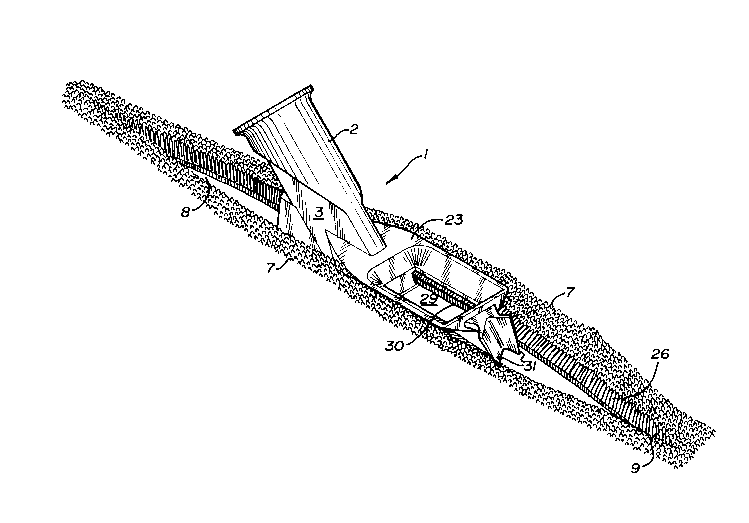
2 The applicator tip 1 comprises, from top to bottom, a
3 leg portion 2, ankle portion 3 and foot portion 4. The tip 1 has
4 a front or leading edge 5 and a rear or trailing edge 6 when in
use. The tip 1 is adapted for seaming adjacent layers 7 of
6 floorcovering. The layers 7 are in linear, side-by-side,
7 abutting relationship along a line of abutment or seam 8. Once
8 formed, a finished seam 9 extends along the line of abutment.
9 The tip 1 is adapted for use with a plastic s~ueeze
bottle or other container (not shown) containing a supply of
11 liquid adhesive or sealant.
12 The leg portion 2 forms an internally threaded coupling
13 10 at its upper end, for connection with the sealant supply
14 bottle. The leg portion 2 further forms a leg passageway 11
extending longitudinally therethrough.
16 Turning now to the carpet tip of Figures 1 - 7, the
17 ankle portion 3 is generally rectangular in section. It is
18 narrow from its leading edge to its trailing edge, relative to
19 the leg and foot portions 2,4. The ankle portion 3 forms an
ankle passageway 12 which extends longitudinally therethrough and
21 communicates at its upper end with the leg passageway 11. The
22 ankle passageway 12 has side-opening outlets 13 at the juncture
23 of the ankle and foot portions 3,4. An upstanding, laterally
24 extending wall 14 forms a transverse barrier for preventing or
restricting direct rearward flow of sealant issuing from the
26 outlets 13. Stated otherwise, the wall 14 causes the sealant to
27 discharge laterally.
28 The foot portion 4 comprises a pair of downwardly and
29 laterally slanting wedges 15. The wedges 15 have top surfaces
16
2051183
1 16 and a common bottom surface 17. The foot portion 4 forms an
2 internal foot passageway 18 extending longitudinally
3 therethrough. The foot passageway 18 communicates at its upper
4 end with the ankle passageway 12 and has outlets 19 in the bottom
surface 17. The central outlet 19 is positioned to coincide with
6 the seam 8. The remaining outlets 19 are laterally spaced on
7 each side of the longitudinal center line of the bottom surface
8 17. Thus the central outlet 19 may deliver a bead of sealant
9 along the seam 8 and the other outlets 19 deliver beads that are
parallel to but laterally spaced from the seam.
11 A removable bottom plate 20 is attached to the upper
12 wall of the foot portion 4, by screws 21, to provide the bottom
13 surface 17 of said foot portion 4.
14 A pair of wing members 23 project laterally from the
side surfaces 24 of the ankle portion 3. Each wing member 23 is
16 positioned above its adjacent side-opening outlet 13 and extends
17 longitudinally in a generally horizontal plane both forwardly and
18 rearwardly of the outlet. Thus each adjacent associated pair
19 consisting of a wing member 23 and wedge 15 creates means for
bracketing and guiding the upraised marginal portion 25 of
21 floorcovering into the desired close-fitting engagement with the
22 ankle portion side surfaces 24. The wing member 23 is also
23 operative to bend the pile 26 outwardly when the tip is being
24 used to seam carpet, as shown in Figure 10.
At their rear ends, the wing members 23 are connected
26 by a cross-member 27. The cross-member 27 functions both to
27 brace the wing members 23 and to serve as a support for the wiper
28 28.
2051183
1 The wing members 23 and cross-member 27 combine to form
2 a window 29, to provide visual access to the "work area" or the
3 open seam 30 immediately downstream of the side-opening outlets
4 13.
The wiper 28 comprises a pair of blades 31 arranged in
6 an upstanding and rearwardly opening V-like configuration. The
7 blades 31 are positioned and adapted to scrape excess sealant
8 from the upstanding side edges 32 of the floorcovering layers 7
9 and to cause this scraped sealant to move downwardly. Some of
the conveyed sealant reaches the undersurface 33 of the
11 floorcovering layer 7, immediately adjacent the seam 8.
12 As shown in Figure 12, each wedge top surface 16 may
13 be recessed to form a shallow channel 35 extending laterally from
14 the adjacent side-opening outlet 13. Sealant can enter this
channel 35 to wet the undersurface 33 of the floorcovering at the
16 seam 8.
17 Turning now to the alternative embodiment shown in
18 Figures 8, 9, 11 and 12, a downwardly projecting, narrow keel 36
19 of small height is provided and extends along the longitudinal
center line of the foot portion bottom surface 17. The provision
21 of the keel 36 greatly reduces drag if the tip 1 is pressed down
22 against the adhesive-coated sub-floor 34 and is pulled therealong
23 in steady contact therewith. Th'is provision enables the
24 installer to maintain the tip parts at a consistent elevation,
thereby improving the quality of sealant application.
26 In the tip version of Figures 13 and 14 a pair of
27 shallow outrigger keels 37 project downwardly from the two bottom
28 side edges of the foot portion 4.
18
20~1183
1 While the preferred form of the barrier is the wall 14
2 of Figure 2, which joins and is integral with both the ankle and
3 foot portions 3,4, it is contemplated that partial wall members,
4 as shown in Figures 15(a), 15(b) and 15(c) could also be used.
In operation, the wedges 15 of the tip 1 are inserted
6 at the seam 8 beneath adjacent marginal portions 25 of the
7 floorcovering layers 7. The wedges 15 function to raise and tilt
8 the marginal portions 25, so that an open seam 30 results. The
9 wing members 23 contact the top surfaces of the upraised marginal
portions 25 and bend the floorcovering downwardly a~slight amount
11 to bring the side edges 32 into snug engagement with the side
12 surfaces 24 of the ankle portion 3 and with the side-opening
13 outlets 13 formed therein. The sealant flow out of the leg and
14 ankle passageways 11, 12 is thus delivered laterally to the side
edges 32. The wall 14 acts as a barrier to reduce the escape of
16 sealant directly downstream into the open seam 30. The close-
17 fitting floorcovering side edges 32 and barrier wall 14 combine
18 to create a closely enclosed chamber or plenum. As a result,
19 manual squeezing of the supply bottle creates backpressure in the
passageways 11, 12, 18. Sealant moves into the foot passageway
21 18 and is extruded through the foot outlets 19 and is delivered
22 as beads to the sub-floor, not only beneath the finished seam 9
23 but also in spaced parallel alignment on each side thereof. As
24 previously stated, the keel 36 or keels 37 can be used, to enable
the installer to press the tip 1 into contact with the sub-floor
26 34 and maintain a consistent elevation. The wing members 23 bend
27 the pile 26 away and to the side in the region of the seam 8,
28 thereby rendering the area of sealant application visible through
29 the window 29. The wiper blades 31 function to scrape excess
2051183
1 sealant from the top area of the seam 8 and convey it downwardly
2 between the floor covering side edges 32, while simultaneously
3 pressing down the treated marginal portions 25.
4 The foregoing description has been directed to the
specific best mode embodiment of the tip. The scope of the
6 invention is now defined by the claims following below.