Language selection

Search

Patent 2051262 Summary

Third-party information liability

Some of the information on this Web page has been provided by external sources. The Government of Canada is not responsible for the accuracy, reliability or currency of the information supplied by external sources. Users wishing to rely upon this information should consult directly with the source of the information. Content provided by external sources is not subject to official languages, privacy and accessibility requirements.

Claims and Abstract availability

Any discrepancies in the text and image of the Claims and Abstract are due to differing posting times. Text of the Claims and Abstract are posted:

  • At the time the application is open to public inspection;
  • At the time of issue of the patent (grant).
(12) Patent: (11) CA 2051262
(54) English Title: SEALING ARRANGEMENT WITH OVERPRESSURE RELIEF
(54) French Title: DISPOSITIF D'ETANCHEITE AVEC DETENTE DE SURPRESSION
Status: Expired and beyond the Period of Reversal
Bibliographic Data
(51) International Patent Classification (IPC):
  • F16J 15/00 (2006.01)
  • F16J 15/16 (2006.01)
  • H02B 13/065 (2006.01)
(72) Inventors :
  • CHABALA, LEONARD V. (United States of America)
(73) Owners :
  • S & C ELECTRIC COMPANY
  • S&C ELECTRIC COMPANY
(71) Applicants :
  • S & C ELECTRIC COMPANY (United States of America)
  • S&C ELECTRIC COMPANY (United States of America)
(74) Agent: OSLER, HOSKIN & HARCOURT LLP
(74) Associate agent:
(45) Issued: 2002-05-28
(22) Filed Date: 1991-09-12
(41) Open to Public Inspection: 1992-04-02
Examination requested: 1998-07-20
Availability of licence: N/A
Dedicated to the Public: N/A
(25) Language of filing: English

Patent Cooperation Treaty (PCT): No

(30) Application Priority Data:
Application No. Country/Territory Date
07/591,156 (United States of America) 1990-10-01

Abstracts

English Abstract


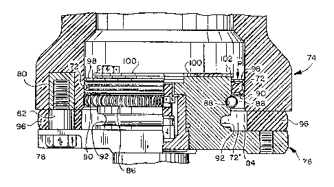
A sealing arrangement is provided with overpressure relief. In the preferred
embodiment, the sealing arrangement includes a sealing member that is
positioned between
two housing portions or the like and that is acted upon by the pressure within
the housing.
A force-responsive retaining arrangement maintains the sealing member in a
predetermined
location, Upon the occurrence of overpressures exceeding a predetermined
value, the
sealing member exerts sufficient force on the force-responsive retaining
arrangement so as
to cause appropriate displacement of the sealing member to permit the venting
of the
housing.


Claims

Note: Claims are shown in the official language in which they were submitted.


The embodiments of the invention in which an exclusive property or privilege
is claimed
are defined as follows:
1. ~A sealing arrangement for a housing including two housing portions
comprising:
means for defining a passage between the two housing portions when
assembled in a predetermined mariner, said passage communicating the interior
and the
exterior of the housing;
a sealing member being disposed in said passage and being compressed
between the two housing portions so as to define a sealing area along said
sealing member
and across said passage with said sealing member being subject to the pressure
internal of
the housing acting in a first sense with respect to said sealing member; and
retaining means independent of, cooperating with, and adjacent said sealing
member for providing a restraining force to said sealing member in response to
internal
pressure acting in said first sense such that for pressures below a
predetermined value the
sealing function is uniformly maintained and for permitting abrupt movement of
said
sealing member in response to internal pressure equal to or in excess of said
predetermined value acting on said sealing member in said first sense
resulting in
overpressure relief via abrupt movement of said sealing member with said
passage so as to
vent the interior of the housing over substantially the entire sealing area.
2. ~The sealing arrangement of claim 1 wherein said sealing member is an
annular member.
3. ~The sealing arrangement of claim 1 wherein said retaining means
comprises means for defining an upstanding wall adjacent said sealing member.
4. ~The sealing arrangement of claim 1 wherein said retaining means
comprises a spring disposed on the exterior of said sealing member.
-6-

5. The sealing arrangement of claim 4 wherein said spring and said sealing
member are disposed as annular members, said retaining means further
comprising a recess
defined within one of the two housing portions for receiving said spring.
6. The sealing arrangement of claim 1 further comprising means for preventing
said sealing member from moving toward the interior of the housing in response
to negative
internal pressures.
7. The sealing arrangement of claim 1 wherein said passage includes a first
portion
in which said sealing member is disposed and a second portion having a lamer
expanse than
said first portion into which said sealing member passes to vent the interior.
8. The sealing arrangement of claim 7 wherein said expanse of said second
portion
of said passage is sufficient to permit passage of said sealing member out of
said passage and
to the exterior of the housing.
9. The sealing arrangement of claim 1 wherein said retaining means comprises
first
means that is acted upon by said sealing member and that is displaced during
the overpressure
relief.
10. The sealing arrangement of claim 9 wherein said passage includes means for
receiving and retaining said first means during overpressure relief.
11. The sealing arrangement of claim 1 further comprising means intermediate
said
sealing member and said retaining means for transmitting forces applied to
said sealing
member to said retaining means.
-7-

12. The sealing arrangement of claim 1 further comprising frangible means
disposed in said passage exteriorly of said sealing means for sealing said
passage to the
exterior, said frangible means becoming disintegral during overpressure
relief.
-8-

Description

Note: Descriptions are shown in the official language in which they were submitted.


CA 02051262 2002-O1-16
SEALING ARRANGEMENT WITH OVERPRESSURE RELIEF
BACKGROUND OF THE I)WENTION
Field of the Invention
The present invention relates generally to the field of sealing arrangements
and more
particularly to a sealing arrangement that provides a pressure-relief function
in the presence of
overpressures.
Description of the Related Art
Various arrangements are known to provide a seal between two housing parts
thereby
;sealing between the inside of a housing and the outside atmosphere. In
typical arrangements, a
;sealing member is compressed, either directly or indirectly, between two
surfaces. For
example, see U.S. Patent No. 4,583,750.
Additionally, overpressure relief arrangements are exemplified in U.S. Patent
Nos.
X4,775,849, 3,952,233, 3,733,452, 2,915,674, 3,229,848, 4,229,723, 4,484,247,
and
4,102,469. The first three patents utilize a displaceable valve or piston
responsive to overpres-
2 o s~ures. The remainder of these arrangements (and the '452 patent) provide
frangible members
which are fractured or punctured by overpressure conditions.
While these arrangements may be generally suitable for their intended use,
they are
complex and/or require independent sealing arrangements and overpressure
relief arrange-
naents.

~~~~~~9 ~v
SUMMARY OF THE INVENTION
Accordingly, it is a principal object of the present invention to provide a
sealing
arrangement wherein a sealing member is responsive to overpressure and serves
as a displace-
able member for overpressure relief.
It is another object of the present invention to provide an overpressure
relief arrange-
ment which utilizes a sealing member that is acted upon by overpressures and a
force-
responsive retaining arrangement that is displaced by the sealing member in
the presence of
predetermined overpressures.
These and other objects of the present invention are efficiently achieved by a
sealing
arrangement with overpressure relief. In the preferred embodiment, the sealing
arrangement
includes a sealing member that is positioned between two housing portions or
the like and that
is acted upon by the pressure within the housing. A force-responsive retaining
arrangement
maintains the sealing member in a predetermined location. Upon the occurrence
of overpres-
sures exceeding a predetermined value, the sealing member exerts sufficient
force on the force-
responsive retaining arrangement so as to cause appropriate displacement of
the sealing
member to permit the venting of the housing.
BRIEF DESCRIPTION OF THE DRAWING
The invention, both as to its organization and method of operation, together
with
further objects and advantages thereof, will best be understood by reference
to the specifcation
taken in conjunction with the accompanying drawing in which:
FIGS. I, 2, and 3 are cutaway views, partly in section, of three respective
embodi-
menu of the sealing arrangement of the present invention.
-2-

DETAILED DESCRIPTION
Refernng to FIG. 1, the sealing arrangement 10 of the present invention
provides a seal
between a first housing portion 12 and a second housing portion or end cap 14.
For illustra-
tive purposes only, the housing portions 12,14 are generally circular and are
assembled via
fasteners 16,18 and an intermediate standoff or spacer bushing 20. The sealing
arrangement
includes a sealing member 22 that is compressed between the housing portions
12,14 which
define an annular space or passage 24. In the specific illustration, the
sealing member 22 is an
annular ring of an elastomeric material. The second housing portion 14
includes an annular
10 ridge or wall 26.
Internal pressure at P within the housing acts upon the sealing member 22. For
a range
of internal positive pressures up to a predetermined value P1, the sealing
member 22 is
retained as shown and the seal is maintained. If the pressure P exceeds the
value P1, the
sealing member 22 is displaced since it functions as an annular piston; i.e.,
the force on the
sealing member 22 overcomes the retention provided by the wall 26. For
example, the
pressure P1 at which venting occurs may be one or two orders of magnitude
greater than the
normal internal pressure P. Upon displacement of the sealing member 22 from
the position
shown in FIG. 1, the sealing member moves through the passage 24. As the
sealing member
22 moves to a position where the cross-section of the passage 24 is larger
than the cross-
2 0 section of the sealing member 22, the internal pressure is relieved via
venting at 28. The
sealing member 22 may be retained at 22' or may be vented with the release of
fluid at 28.
It will be apparent from the foregoing that the dimensions of the passage 24
are dictated
by the cross-section of the sealing member 22 such that appropriate venting is
provided and to
ensure that the sealing member 22 does not block the venting pf fluid in the
passage 24 after
the sealing member 22 is displaced past the wall 26.
In the arrangement of FIG. 1, an annular gasket 30 is disposed at the
periphery of the
passage 24 to provide a weather seal, etc. to the environment. Of course, upon
overpressure
-3-

,~~'~~~~i~'(irw~.
release, the gasket 30 is displaced, severed, and/or disintegrated to permit
the desired venting.
Additionally, an aperture ring or a plurality of spacers 32 are provided for
embodiments where
negative interior pressures may be developed; e.g., where the interior is
evacuated prior to
filling with a desired fluid for the particular purpose. The ring or spacers
32 serve to prevent
the sealing member 22 from being displaced inwardly from the normal position
as shown in
FIG. 1.
Considering now another embodiment and refernng to FIG. 2, the sealing
arrangement
50 includes a sealing member 52 compressed between two housing portions 54,56
which are
relatively positioned together to define a passage 58. A garter spring 60 is
disposed around the
periphery of a sealing member 52 so as to retain the sealing member 52 in the
sealing position
of FIG. 2 under normal conditions. If an overpressure P exceeding P1 should
occur, the
pressure exerts force on the seal member 52 which is transmitted to the garter
spring 60 so as
to displace the sealing member 52 and expand the garter spring 60 sufficiently
to provide
venting of the interior; the sealing member 52 and the garter spring 60 being
moved either to
the outside of the housing portion 54 or into the widened relief area at 62.
Where desired, a
spacer or slotted ring 63 is provided to ensure against the movement of the
sealing member 52
into the interior. Similarly to the gasket 30 of FIG. 1, a gasket 64 is
provided for weather
sealing. As shown in FIG. 2, a covering bmd 66 may also be provided which
includes
suitable vent holes.
2 o Referring now to a third embodiment in FIG. 3, the sealing arrangement 70
includes a
sealing member 72 compressed between two housing portions 74,76 which are
fastened
together via a threaded bolt 78, a threaded sleeve 90, and a spacer 82. The
arrangement is
especially adapted to the housing of a gas-filled circuit interrupter. The
arrangement defines a
passage 84 having both longitudinal and circumferendal expanses as shown in
FIG. 3. A
garter spring 86 is positioned within an annular groove or recess 88 adjacent
the sealing
member 72. A washer 90 is disposed intermediate the sealing member ?2 and the
garter
spring 86. The washer 90 functions to transmit the farce an the sealing member
72 t~ the
_4_

garter spring 86 in an efficient and focused fashion. A relief area or groove
92 is provided in
the housing portion 76 to provide a defined position for the garter spring 86
upon displacement
due to overpressure relief.
Upon the occurrence of sufficient overpressure P in excess of P1, the force on
the
sealing member 72 displaces the sealing member 72, the washer 90, and the
spring 86, with
the spring 86 moving rapidly from the position in groove 88 to the groove 92;
the washer 90
either fracturing, fragmenting or disintegrating, and the sealing member 72
moving to a ___ .
position 72' or being vented out the passage 84 at 94. As discussed
previously, a gasket 96
similar to gaskets 30 and 64 is provided. To prevent movement of the sealing
member 72 into
2o the interior of the housing, a washer 98 and a retaining ring 100 are
provided. The retaining
ring 100 includes circumferential portions which extend at 102 to a sufficient
extent to retain
the sealing member 72 in the presence of a predetermine range of negative
interior pressures.
Concerning each of the embodiments of FIGS. 1-3, the sealing member is
fabricated
along with the housing portion to have predetermined dimensions so that the
sealing member is
suitably compressed to provide a desirable sealing force when assembled. For
example, in
FIG. 3, the sealing member 72 is fabricated to provide an appropriate
interference fit with
respect to the housing portions 74,76 when assembled. The sealing member 72
may be lubri-
cated to aid the assembly of the housing portion 76 with supported sealing
member 72 into the
housing portion 74.
2 o i~Vhile there have bin illustrated and described various embodiments of
the present
invention, it will be apparent that various changes and modifications will
occur to those skilled
in the art. For example, it should be specifically understood that the shape
of the sealing
member and the sealing surface of the housing portion may be any shape as
dictated by the
particular application and practical considerations. Accordingly, it is
intended in the appended
claims to cover all such changes and modifications that fall within the true
spirit and scope of
the present invention.
-5-

Representative Drawing
A single figure which represents the drawing illustrating the invention.
Administrative Status

2024-08-01:As part of the Next Generation Patents (NGP) transition, the Canadian Patents Database (CPD) now contains a more detailed Event History, which replicates the Event Log of our new back-office solution.

Please note that "Inactive:" events refers to events no longer in use in our new back-office solution.

For a clearer understanding of the status of the application/patent presented on this page, the site Disclaimer , as well as the definitions for Patent , Event History , Maintenance Fee  and Payment History  should be consulted.

Event History

Description Date
Time Limit for Reversal Expired 2010-09-13
Letter Sent 2009-09-14
Inactive: IPC from MCD 2006-03-11
Grant by Issuance 2002-05-28
Inactive: Cover page published 2002-05-27
Pre-grant 2002-03-04
Inactive: Final fee received 2002-03-04
Notice of Allowance is Issued 2002-01-30
Letter Sent 2002-01-30
Inactive: Received pages at allowance 2002-01-16
Inactive: Office letter 2001-11-21
Inactive: Approved for allowance (AFA) 2001-11-01
Amendment Received - Voluntary Amendment 2001-05-18
Inactive: S.30(2) Rules - Examiner requisition 2000-12-07
Letter Sent 1998-08-17
Inactive: Status info is complete as of Log entry date 1998-08-17
Inactive: Application prosecuted on TS as of Log entry date 1998-08-17
All Requirements for Examination Determined Compliant 1998-07-20
Request for Examination Requirements Determined Compliant 1998-07-20
Application Published (Open to Public Inspection) 1992-04-02

Abandonment History

There is no abandonment history.

Maintenance Fee

The last payment was received on 2001-08-23

Note : If the full payment has not been received on or before the date indicated, a further fee may be required which may be one of the following

  • the reinstatement fee;
  • the late payment fee; or
  • additional fee to reverse deemed expiry.

Please refer to the CIPO Patent Fees web page to see all current fee amounts.

Owners on Record

Note: Records showing the ownership history in alphabetical order.

Current Owners on Record
S & C ELECTRIC COMPANY
S&C ELECTRIC COMPANY
Past Owners on Record
LEONARD V. CHABALA
Past Owners that do not appear in the "Owners on Record" listing will appear in other documentation within the application.
Documents

To view selected files, please enter reCAPTCHA code :


To view images, click a link in the Document Description column. To download the documents, select one or more checkboxes in the first column and then click the "Download Selected in PDF format (Zip Archive)" or the "Download Selected as Single PDF" button.

List of published and non-published patent-specific documents on the CPD .

If you have any difficulty accessing content, you can call the Client Service Centre at 1-866-997-1936 or send them an e-mail at CIPO Client Service Centre.


Document
Description 
Date
(yyyy-mm-dd) 
Number of pages   Size of Image (KB) 
Abstract 1993-11-03 1 15
Cover Page 1993-11-03 1 14
Claims 1993-11-03 3 100
Drawings 1993-11-03 1 52
Description 1993-11-03 5 209
Claims 2001-05-18 3 84
Cover Page 2002-05-08 1 60
Description 2002-01-16 5 210
Representative drawing 1999-07-07 1 27
Representative drawing 2002-05-08 1 32
Reminder - Request for Examination 1998-05-14 1 117
Acknowledgement of Request for Examination 1998-08-17 1 194
Commissioner's Notice - Application Found Allowable 2002-01-30 1 164
Maintenance Fee Notice 2009-10-26 1 170
Correspondence 2001-11-21 1 21
Correspondence 2002-01-16 2 59
Correspondence 2002-03-04 1 36
Fees 1996-08-30 1 59
Fees 1994-08-29 1 55
Fees 1995-09-06 1 31
Fees 1993-09-07 1 34