Note: Descriptions are shown in the official language in which they were submitted.
~ ~ O90/12710 2 0 514 2 7 PCT/US90/02151
--1--
RE~RACTOR WITH AUXXLIARY
ERA~E ~ECHANIS~
,
Backqround of the Invention
The invention relates generally ito a safety belt
retractor' and more particularly to a safety belt
retractor having a brake mëchanism which acts directly on
the belt and operates in conjunction with a reel-locking
mechanlsm .
^ A typical safety bëlt retractor inciudes a
spring-biased reel on which a léngth of safety belt
webbing is wound, and an inertial reel-locking mechanism
. : .,
whlch locks the reel against rotation to prevent
protraction of' the webbing in the evënt of a situation
where passenger restraint is needed. Locking of the reel
does not necessarily preclude`any furth2r protraction of
the belt, because the webbing may cinch on the rëel when
under high ~ension. Several proposals for improved
retractors provide for a mëchanism which clamps or grips :
the webbing directiy to stop protraction, either in
'conjunction with or lnstead of the reèl locking
mechanismO While such clamplng arrangements may provide
~.~ 3~-- ~ -r;--~,~ Jc^. r ~ -J ï rir~ r -~i~; ` r~ .~. 7' .J . î ~.f~
improved control ovêr ~elt protraction, th8y also prr~sent
certain problems.
' ~ Onè problèm is that the gripping or clamping
25 - mechanism must engàge the webbing securëly enoùgh to
arrest~its ~ovement while the webbing is sub~ected to a
r ~ ~- f ; ., ~ f z. ~ f ! ~
`'high~tensile ioad;f without damaging thë we~bing. The
tenslle load on ~he belt may greatly exceed the weight of
~ in~ Z~ f ~ J ~ f~ rr,~t ~jjf .~ '.S .: ...~.. '~`.
the~passenger ln the even~ of a colli6ion. To meet
~r,.. S~J .~ 'i^ v~.; {'.t~ .... :7 i`~ !r''~r, r,~
"manuPacturlng ~tandards, the clamping ~echanism must be
capable of repea~edly constraining the belt against
1 r: ~- r~ L ~ s ~ sY, I --, ~ Y.~ .f,7~
tensile loads of abou~ l600 lbs; without ~amage to thë-
r ~ r~ t ~ 3 { ;~f ,~ J ,~ Q t !~ s~ i r~ S-J
~- belt. A mechanism w~ich causës fraying'or other damage
to'the belt`webbing is unacceptable even i~ it is
35 otherwisè~effectii~vé~rn~Lf~ X~ J~ "~ fi~
. ., , ~ , , ~ ..
: :
.; , . . ..
' :, '
.
-
, ~
. .
WO 90/12710 PCT/US90/02151
-2-
A relatively early proposal for a clamping
device is set forth in U.S. Patent No. 3,467,337. As
disclosed at column 4, line 15 et seq., and shown in
FIG. 2, the clamp 60 in this patent has a curved edge 78
which engages the belt 29. This clamping mechanism
illustrates one general approach to the problem of
avoiding belt wear, in which the belt is engaged by a
rough or toothed surface on one side, and a smooth
surface on its opposite side, with the rough or toothed
surface moving in the same direction as the belt during
clamping, so as to reduce or eliminate movement of the
rough or toothed surface relative to the belt. One
disadvantage of the arrangement shown in Patent No.
3,467,337 is that only a relatively small portion of the
clamp surface area engages the belt due to its
curvature. This may result in unacceptable stress
concentrations on both the belt and the clamp.
Another proposed retractor with a belt-clamping
mechanism is disclosed in U.S. Patent No. 4,544,112, in
which wedge-shaped members cooperate to clamp the belt.
A problem with this arrangement is that the clamping
mechanism jams, or reaches mechanical equilibrium, after
closing on the belt, and cannot be opened merely by the
force of the spring which provides rotational biasing on
the reel. Accordingly, a manually operable release must
be provided, which is inconvenient to the wearer.
U.S. Patent No. 4,394,034 discloses a retractor
in which a movable frame 40 supports a reel 70. When the
reel locks, the frame travels upward and a clamping
member 84 carried on the frame clamps or wedges the belt
against abutment surfaces of a belt passage 100. This
retractor relies on a wedging action to provide a
mechanical advantage so as to enable high enough clamping
forces to be achieved. However, it is believed that if
this clamping mechanism is configured so as to provide
~ 09D/12710 2 ~ a 1~ 2 7 PCr/US90/02151
-3-
sufficiently high clamping forces, it will be difficult
to withdraw the clamping member from engagement wi~h the
~elt after clamping occurs, without a manual release.
Another proposal is illustrated in U.S. Pat~nt
No. 4,687,253,"which.,illustrates,various proposals,for a
clamping mechanism used in conjunction with a reel
supported.in elongated,slots. .
While various other proposals for clamping
mechanisms have been made, such mechanisms often require
10 a unique,or complex retractor and complex wedges or : '
wedging actuators which do not readily release the belt. . . .
The use of a conventional retractor operating in
conjunction with a small and simple, pivoted ~:.
belt-clamping or braking means operable by a cam which
does not damage the belt and readily releases..by itself
. has not heretofore been,attained.- , ,~ -
. , ,. ,It-is a general object of the invention to..
provide an;improved"safety belt retractor which includes
a reliable brake mechanism that acts directly on,the.belt
20. and operates in~conjunction with a reel-locking
mechanism. ,-~, ..~- - :, ... .. . .
~ ,,FurtherA,,objects,of the,invention:are disclo~ed
-.bslow.~-~ 3'"~
3~ Summary~of the Invention~
~ In,accordancP,,with~one aspect,of the;,invention,
there is,A,provided a~safety,belt~re ractor:which,may,be a
,conventional~jxetractor.moun~ed,for.sliding,~moYement:.in a
~"~a,s,e;-,to,-be,j~'ixedly^,mounted.on the vehicle.~.,sA~braking~
mechanism is,pivotallyi~m~unted;.on,~-.thel:,base,~and a~cam pin
r~an~ he,,.6lidable retractor,iwill,cam against.and pivot the~)".
braking,mechanism~*o!stop,~,belt;protraction.-,-,This~,action
occurs when a conventional inertia-~ensitiv,e.device,~
operates~tor~lock~he reelca~ainst~:rotation~ ~o that
subsequent.belt,tens,ipn~displaces,~he,:movable retrac~or
and carri~s,rits~.cami,pin ~to;.:~,engage,~andn~o.,~hift,,:a,~brake ;.
. shoe int~,~dire.ct,con,t.a.ct-~-withr.,~he belt webbing. The
.: , . . - , :
. . :. . . :,
.', " ' - : .
... . : .. , .. ... : . .:
~'' ,.' . .' , ." . ' . ' : .' ' :
' ' ' ' . ' '
WO90~12710 . .? . PCT/US90/02151
--4--
brake shoe is supported on the cam for movement relative
thereto. The brake shoe and the cam preferably have
complementary interfitting bearing surfaces which share a
common axis of curvature, with the bearing surface on the
brake'shoe-~eing convex, and the complementary~surface on
the cam being concave. The brake shoe preferably has a
radial dimension less than the radius of curva~ure.of its
bearing surface.
The configuration of the braking'mechanism may
be described with reference to~a first plane:defined by
the axis of rotation-of the cam and the axis'of curvature
of the bearing surfaces, and a second plane defined by
the belt webbing adjacent the brake shoe. The angle"
between the first plane and a line pérpendicular to the
-second plane is preferably between about-19 and about
29~ when ~he brake shoe is-in its locked position. This
configuration enables the braking mechanism-'to achieve
^acceptably high braking'forces~while being-automatically
releasable.:upon release of belt:tension. ::
The brakingisurface o~ the brake shoe-preferably
~mploys a plurality of teeth to penetrate intersticès~'in
Jthe.webbing for-positive engagement between:'the brake
shoe and the webbing. Each o~ the teeth preferably:has a
substantially.triangular.transverse:'face for engaging the
25 ~-the webbing, and-sloping';back surfaces behind the '
; .transverse~face which permitrthe teeth to withstan~ ~IJ
. relaitively high belt tension'~o arres~ protraction o~ the
belt;Jwithout~interfering~t'with''~ubsequent:re~'racti`on~iof
~ the~belt following!-release"~oflbelt'tension.r '`'; '::s-'`-'3i~
30 ~a'~ Further;'aspects of'the''~inventionr'ar~e~dis'clos'ed i'
~in~:the description-and cl'aims.~are~set~'forth-beilow','i~'àn'~ in
the~raccompanying drawings.' f~ t',l~
t1J~ Brieit'~ ;t riP~ ion ~ol~ Dra~ingLs`;i r~ ~ ~ri~j -
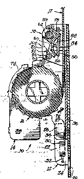
^~o ')~ 'r FIG,''~ is''~a-~ront'~elevatl'onal-'view~o~'a';~ .
:retractor in accordance'''with;:~the'inve`ntion.'~3r'~ t;~ t 'S ' ~'
~s'~:~ :'FIG--~2 i's1t:a~'side"ë~evational'vi~w;o~'~he _301'~C'i
Fetractor o~ FIG- l.
,~
. . - . ,. .: . ~ : , . .'
.. . . .
.
.
, : . . ~
' :
WO90/12710 2 0 ~ 1~ 2 7 PCT/US90/02151
--5--
FIG. 3 is an enlarged front elevational view of
the braking mechanism of the retractor o~ FIG. 1.
-FIG. 4 is an enlarged ~ide elevational view of
the braking mechanism of the re~ractor of FIG. l, shown
5 with the braking mechanism in its braking position. f
FIG. 5 is an enlarged side elevational view
similar to that of FIG. 4, but showing the braking
mechanism in its inactive position.
Detailed D~scription o~ Preferred ~mbodiment`
The.invention is generally e~bodied in a safety
belt retractor lO comprising a fixed base 12, a frame 14
slidably supported on the base 12, a reel 16 rotatably
supported.on the frame.with a length of webbing 17 wound
thereon, and a belt-engaging mechanism or:~raking
l5 mechanism 18
~- . The base has a back wall 19 which is-adapted to
be af~ixed~to a supporting.surface on the vehicle, e.g.,
the vehicle door frame. .To support and constrain the
braking mechanism 18 and.the movable frame, upper:and
20 lower pairs o~ side members 20 and.22, respectively, are : :
disposed generally.perpendicular to the back wall lg of
the base ~l2" on.opposite;sides.thereof,.Pxtending away
from the support sur~ace.;~The.lower side members-22-,are
generally L-shaped,:;each having a lower..portion.~24; :~
connected to the back wall.o~ the base and an upper
portion 26 extending..upward therefrom so:as tb define a
slot 27.between the.upp~r.portion 26 and the.back wall l9
~-,for 6lldably receiving-.a-~lower,portion :of the.frame 14 as
- described below.:iThe base l2~has:a.circular.~.opening-28
near the~lower~ond.,:o~.Lthe:back.wall to.receive.a~bolt or~
he1jlike,to.~ecure.the,base.. toAthe frame.. a.,.. ~ s;~j i
The, frame.-l4i,is,~movable between a lower;position
~(shown in~_FIGS...-l~and.r~2),corresponding.~o..normalm: ~t.i,r~ ~
~jO-...operation and.an~upper,jposition (FIG.t4~;corresponding to
.~emergency,~,locking~of.the,retractor-lO.t~;The!~frame~ 4~is '
.,.~biasedj;.toward~it~..lower poi~ition;by~a pair of coil.-mr
.
.
. .
.
.
' '
., ' ' " '' ' ' '
W~90/12710 ~ ~ ~ 1 ~ 7 PCT/US90/02151 ~
--6--
springs 30 loaded in tension. The springs 30 have their
lower ends 32 affixed to lower portions of the lower side
members 22 of the base 12, and have their upper ends 34
affixed to the frame.
~ The frame 14 preferably comprises a back wall 36
which slides against the back wall 19 of the base, and a
pair of sidewalls 38 which extend outward from the back
wall 36 to support the reel 16. The frame 14 is
constrained for`rectilinear.vertical travel relative ~o
... ..
the base 12. The lower portion of the back wall of the
frame is received in the slots 27 defined by the lower
side members 22 and back wall-l9 of the base 12. The
lower snd of the frame 14 is-ma!~ntained centered by
abutting sliding engagement between the sidewalls 38 of
the frame and the lower side members 22 of the base 12.
The upper.end of:the frame 14 is similarly constrained by
engagement between.the upper.portions of the frame
sidewalls.38 and the upper side members~20 o~ the base,
and.by a pin ~0 which extends between the sidewalls 38 of
the frame 14 through.a pair o~'vertically-elongated ~
slots 42 in the upper side members 20 of the baseO''In
addition.to constraining the frame 14 relative~to the
ase.12,;the pin 40;performs a~camming function in'the
braking:mechanism as described below. ' '~
25 .,.. - , .The reel 16 is supported~onia shaft 44 which'
.:extends through the..opposite.sidewalls o~ th`e frame'.-~
.~ ,conventionalispiral~y-wound:sp~ing assembly~'~6 is -: ~
~, provided.at.one end of,~,thel~shaft to'bias the reel~1'6`for
~retraction.~ A;conventional~reel-locking mechani'sm '4R`is
30 _oused.,to lock-the~reel-~16'in'response~to-rapid~'^J ~
acceleration ~fathe-vehicle in any~diract^ion;'or-ùpse~ of
~,r:the~.yehicle.; The-re~l-locking mechanism;employs an
inertia~ensitive'weight~70~to`:pivot'~a l'o~ing pawl ~2
o~ ~intoi.engagement with'ratchet~'wheelsi74;'whe'n thë;ret'ractor
35 x.;exp'eriences~`igh accelerati'on''or`displ'ace'mènt'~from~ 's
normalrorientation;i~ A''reel-'sens'i~'ive'iner~ia~mèans''may
I
, . ,
. :
.,
- ,' ~ .
'
~ O90/12710 2 0 ~ ~ ~ 2 7 . PCT/US90/02151
_7_
be attached to the reel shaft to stop further shaft
rotation at a predetermined rotational veloc.ity for the
reel. The preferred sPat belt retractor is a commonly
used and conventional retractor to which is added the
braking mechanism and~the base on which the conventional
retractor is mounted. The camming pin 40 is added to the
conventional retractor.
- The webbing brake-18 is supported between the
upperrside members 20 of the base 12 and is~movahle ~
between an inactive position in which:the webbing 17 can
move freely, and a braking po~ition in~which the webbing
17 is constrained against protraction by engagement with ~-
a brake shoe 50. . . ...
~ In accordance with a feature of the invention,
the brake shoe 50 is supported by a pivoting.cam 52 which
is.normally biased away from the-webbing 17, but which is
cammed.to bring the braXe shoe 50 into enyagement with
the webbing 17 by the pin 40 upon.upward travel-of the
frame 14. The-cam has a concave, part-cylindrical
:bearing surface 54 for receiving the brake shoe ~O, which
has-~a~:complementary, part-cylindrical convex bearing
.~surface~56 on~its back~ a~ s
~ The cam:52 is supported:on the pivot.-'pin~:58 by
cylindrical~:coIlars;~62 which.extend:.ioutward on-'opposite
si~es:~ther20f. :The pin.58 extends~.through.the upper:side
members:20 of:the~base~l2,~and-is biasèd.away from the
webbing sur~ace byia.~pair3O~;:springs:~60. t~; The~springs 60
are looped:around'thé collarsl62 onithe opposite'sid s of
;--the'cam.~ Each~springlhas~ma lower Ieg 64 extending~down
and away ~'rom the back of the base to engage the camming
~5.~$~i~pin,~-3and an~uppersleg 66 with:a~hook~at,its.end engaging
~a`trunnion:,633~n.~the cam;!52..J~ilTh.-springs.biasjthe:cam 52
in~a~cloc~wise~direction a~iviewed'.in~FIG5-. 2;-'4~and~5,
~'.whilesalso~maintaining~-the~brake~hoe)~50sin~contact~.with :
35 r5 ~ ~the~-cami:52O~ heibearing sur~ace~54~;of;nthe ! cam-52'i :
' .'. ' ~ : . . ':
.. . , , ., ~ ,
.. . . ... . . . . .
WO90/12710 2 ~ 5 1~ 2 7 PC~/US90/021
-8-
backed by a pair of longitudinally extending sidewalls
76, a trough-shaped transverse stiffener 78, and a
plurality of longitudinally-extending gussets 80.
To provide for positivej non-sliding contact
between the brake shoe 50 and the webbing 17 with minimal
wear on the webbing, the brake shoe 50 has a braking
surface 84 composed of a plurality of pointed teeth 82.
The points of the teeth 82 are substantially coplanar so
that the entire braking sur~ace, i.e., all of ~he teeth
82, can engage the webbing 17 to distribute braking loads
over a large areaO
~ In one embodiment, the braking surface 84 is
generally rectangular with a longitudinal or vertical
dimension of about 1 in. and a transverse dimension of
about 2 in. The transverse or radial dimension of the
brake shoe, i.e., its maximum dimension perpendicular to
the braking.surface, is about 5/16 in. The bearing
surfaces 54 and 56 on.the cam 52 and brake shoe 50
preferably each have a radius of curvature about a
20, transverse axis P (FIG~.4) cf about 5/8 in. Because the ,.
radius of.curvature is greater than the transverse or
radial dimension of the brake shoe,,50,.i.and specifically
is:about twice the traniveri~e-dimension.of the brake
^ shoe,-~the brake:shoe350.travels.isilightly:upward and -
25 ,,ro~a~es slightly,clockwise relative to the cam during
! braking after~initially.engaging the-belt- -This '
.~,. .facilltates achievement-,of 'J smooth braking:action and
u~ relatively"even~distribution of braking.forces,i~ r
.,,;contributing to effective braking-without damage to:the
30-,~.~j,webbing.-l7-.,~ -.s.., e.~ o".l '^'5^~
Qr; r~f;r~ The-bearing.surface 56 on,the.-brake shoeiis,made
;~n ~îup .~of~a,iplurality of.longitudinally.extending ribs 86
. connected bytia-~centralstransverse rib.8iB.`.ArThe.brake
~ hoe 50~:is~preferably,a:one pie~e plastictmolding.~ iTo
maintaini:~he~brake,~ihoe;50i~centered:.~ion~the.cam:.52,~guide:.
.
. ' ~ ~ . ' '
' ~
~ 090~12710 2 ~ 2 7 PCT/US90/02151
_9_
lugs 90 are provided on opposite sides of the brake shoe
near the lower end, engaging the sides of the cam 52.
To prevent deformation of the back wall l9 of
the base 12 upon application o~ braking forces thereto, a
5...plurality of.transverse ribs 92 are provided to stiffen
the back wall l9 and distribute braking forces. The
forces applied are quite high and the center portion of
the back wall tends to deflect, and7 if allowed to ..
. deflect, causes the brakin~ surfaca to concentrate the ..
forces on.the outer longitudinal edges of the belt to an
extent that the belt is damaged. .By using thick metal
for.the back wall and heavy,~large ribs 92, this problem
is overcome.. To.keep the webbing~l7 flat adjacent the
.brake shoe 50 and spaced from the brake shoe during
. . . . . .. .
normal conditions, and to provide a smooth, generally
planar support.surface for engaging the side:of the
webbing.17 opposite the brake shoe, a plastic web guide
94 is.supported..between the upper side members 20.of the
base.,.between the back wall l9 of the base~l2 and the
... ...
20 .brake shoe 50. .The web guide 94 has contoured~............ .
,, . . . ~ . , . -
longitudinal ribs 96 abutting and interfitting with the
. transverserribs~in the back of~the base 12-to distribute
.. .braking.forces...Spacing-b~tween~the webbing 17 and.the
~ .brakeishoe.50 is maintained py transverse members 98~
which cooperatel;wlth~the smooth,~ planar~support.surface .:.
,..lOO to.define slots...through which the,webbing l7 pasGes.
, In normal.operation~of the r~tractor.-lO,;the
., . , . .. , .. .. . . , . ~ .. . . . ;
frame..l4~xemains~in~it~ lower-position. -~he webbing..17
is.protracted~when.the,~we~rerj-uses the belt,~;and iS ~.7
. subsequently~retractéd~by the..spring~.assembly 46..cWhen .~
the"~v.e~hicle5experiences.rapld~acceleration~or ~ t!
decelerati~n~,.or is;.~upset,;ithe;reel-lockin~ ~echanism 48
locks.-;~the,~reel~l6 aga~n~tj;protra~ctlon.~ Subsequent ~,;!:.'
~ en~sion~onrlth,e.~belt~due to~~movement~o~ thel.wearer~of the
belt~relaki~e,~o.~the interior~of-theLvehicle,-.pulls.*he
.'' ~J .~. C,.l ~i F~ ''t ~ i.f~ ,5~ ^"s ~ p~- ~t-r~
.' '' '
' ' ' ~ ' ' .
W090/127i~ ~0~27` ` ` PCr/US90/02151 ~
--10--
frame 14 upward. As the frame 14 travels upward, the
camming pin 40 slides along the edges 102 of the
sidewalls of the cam 52, pivoting the cam 52 in a
counterclockwise direction toward its braking position~
5 r ` The edges 102'are disposed at an angle of about
40 to the plane of the web support surface 100, when the
.web brake is in open position (FIG 5), and at an angle of
about 50 in closed position (FIG.4). As the frame'14
travels upward, the camming pin 40 travels substantially
parallel to the plane of the web support surface 100,
directly toward the axis of the pivot pin 58.
When the hrake shoe 50 makes contàct with the
web 17, points of the teeth 82 penetrate interstices in
the web 17. The teeth 82 have sloped upper'surfaces 104
and flat, transverse lower surfaces 106 to engage the
fibers of the web. The brake shoe 50 continues to travel
upward for'a short distance with the web`17, rotating
clockwise about axis P relative to the cam 52, as the
cam 52 continues to rotate counterclocikwise relative to
the base 12; ~echanical equilibrium is then reached in
~^the braking position as`shown in FIG. 4. - -
A'fter:tension on the~belt`has beén relëàsed, the
-~caml52 must pivot back''to thé position shown in~FIG. 5 to
pè`rmit normal'retrao~ion"~an`d~'prot'raction of thèibeI`t for
further:use.~'~As noted abové, some-prior retractors ';
;employ-a:cl`amping or:braking mechanIsm-which stays;in-the
locked'or~'clamped po's'it'ion'''after belt t~nsion is
'relëased,5a~ must'-be''shifte'd manuallyito";iti3 unlocked or
ope'n po'siti'on~! 'One'ofth'ë'p'r`oblems''addressed by the
3 n ~bra~ing mech'anism'-`is'~th'è'provision''of~suffici'ëntly'high ''''
braking forces-wit~out~he'use of a' mechanisM-wh'ich~
v~regu'ires'~'ma'nual'resettin'g'aftér use. Basically,- this
requires~that the'~ t~tic':fri~`ionà~.fôrces-resis~ing~
~ 'retr,action'-'of th'e~'lt~'aftë~ b'r'akin'g:~e-;minimal.;-5If the
35 i<'~tatic fric~i'ona'l~force~s'~aré'~to'o h'~ght'~'jàmming~occurs, ?~
~uch that the braking mechanism will not return to its
090~12710 2 ~ 2 7 ~ PCT/U590/021~1
unlocked position. The problem is solved by the
illustrated braking mechanism as explained below.
Referring to FIG. 4, the center of curvature or
axis of the recess on the cam 52 is indicated at point
P. The line extending thrôugh point P an'd'through the
center of rotation about which the cam 52 pivots is
labeled 11. 'The line through the center of curvature P
extending-perpendicular to the'plane of thè web is
labelèd I2. The incl'uded angiè'betweén~~ines ll and
12 is'designated B.'
Susceptibility to jamming is largely dependent
on the value o~ the angle B when the braking mechanism is
in locked position. As B approaches zero, suscep~ibility
:'~o jamming-increases. However, as B incr'eases, the ratio
between tensile forces on the'belt and'normal forces
dzcreases, resulting in decreased braking effectiveness
if B is too large. ' ' '~ ' ' . -
To provide optimum~'performance,~it has been :
''-'found that ~ should be between about l9~ and 29, and '
preferably equal to aboùt-24-.'~With this configuration,
when tension on the belt is released, the cam 52 is
immediately pivoted to its unlocked position.
The shifting of the brake mechanism 18 to the
unlocked or disengaged position is provided by the dual
linear coil springs 30, the spirally-wound spring
assembly 46, the dual cam return springs 60, and the
weight o~ the frame 14, reel l6, etc. The lin~ar coil
springs 30, the spirally-wound spring assembly 46, and
the weight of the reel, etc. cooperate to provide
retractive forces on the web 17. The cam return springs
60 act directly on the cam to pivot it in a counter-
clockwise direction. :
It should be appreciated that the lower leg of
the cam return springs 60 is forced in a clockwise
directio~, away from the web 17, as the camming pin 40
'
,
WO90/12710 2 ~ 2 7 PC~/US90/02151
-12-
travels upward, so that the counterclockwise torque on
the cam 52 exerted by the spring is maximized when the
frame 14 is in its upper position.
From the foregoing, it should be appreciated
that the invention provides a novel and improved safety
belt retractor. In one test on a retractor in accordance
with the invention, it,was found that under a 1600 lb.
tensile load on the belt, protraction of about l.8 in.
occurred due to cinching after,locking of the retractor
in the absence of the braking mechanism, whereas
protraction was reduced to 0.4 in. with the braking
mechanism in operation. This was accomplished without
.
breaking or severely,damaging the belt. The belt- -
braking retractor apparatus uses a conventional retractor
and an inexpensive, simple U-shaped base on which is
pivotally mounted the braking means for being cammed by a
simple cam as the retrartor slides on the basa.- The
invention is not,limited to the embodiment described
above, nor to any particular embodiments, but is pointed
out and described by the following claims. -., ,-
i, :. , .
, ! . ~ ' ' , ' ~, . .
~3-,~ C~ v" ~iJ~ ? ~ .S,-ii '. '(. " ,,~: ,';i,'~3J~J.~
: ' . ' , . ' ~ ,
. .' ':
,'
.
'
.