Note: Descriptions are shown in the official language in which they were submitted.
2~51~
ME~OD AND APPARATUS FOR PRODUCTION OF NETAL BASE
COMPOSIT~ NA~E~IAL
FIELD OF TH~ INVEN~ION
The present invention relates to the metallurgical field, and more
specifically to a method for the production of cast base metal
material having distributed therein very fine particles which can
be particles of ceramics, metals, alloys, intermetallics, carbides,
nitrides, borides and substances useful in enhancing properties of
the base metal.
BACKGROUND OF THE INVENTION
Development of the aircraft and ship building, car making and
a number of other industries require new materials having improved
workability and service properties.
Metal~ic structural materials (alloys) are nowadays produced
by melting the base metal to li~uid form with additive components,
with the melting process going at the temperature of the entire
system which ensures the complete melting and mutual dissolution of
the components (Fig. 2a).
With the drop of temperature of the alloy during cooling and
solidification, the solubility of the alloy components sharply
decreases and, at a certain temperature particular for each alloy
system and composition, solid phases begin to precipitate and grow
from the homogeneous melt in the form of alloy component crystals,
,
20~160~
or, more frequently, in the form of the crystals of the chemical
compounds of components (intermetallic phases) (Fig. 2, b,c). With
further cooling the rest of the melt is crystallized in the form of
a solid solution of the components in the base metal (Fig. 2, d).
Intermetallic phases with crystal lattice and properties different
from those of the base alloy (matrix) strongly affect the
properties of the alloy system as a whole.
The size of the intermetallic phases precipitated in the
process of crystallization of the alloy should not exceed fractions
of one micron, otherwise guality of the alloy will be sharply
impaired due to loss of ductility and strength.
The solubility of metals and metalloids in the metallic matrix
is very much limited in the solid state and this factor accounts
for the narrow selection of commercial alloys and the practically
achieved limit of improvement in the properties of the commercial
structural alloys by change in composition.
A new class of structural materials have been developed, which
contain artificially incorporated particles or fibers of oxides,
carbides and other compounds enabling the attainment of assured
properties of the system as a whole. Such materials are ~nown as
composites since the components of the metallic system are not
precipitated from the matrix metal, as is the case with the
conventional alloys, but are artificially incorporated into the
system. All known metallic alloys representing the matrix with
incorporated particles, whose properties significantly differ from
the matrix, are basically the composites, although of natural
' .: ,
`` 20~160~
occurrence in the making of the alloy.
The properties of metallic materials represented by a composite
system of artificial or natural origin are indicated as follows:
- ductility of the material is determined by ability of the
matrix (as a rule the ability of the solid solutions of components
in the base alloy) for plastic flow, as well as by size and
syngonia (crystalline structure) of intermetalloid and other
inclusions in the matrix);
- strength, heat resistance, fatigue strength, resistance of
materials to development of cracks is determined by interaction of
the of the inclusions and the matrix, as well as distortions of the
crystalline lattice of the matrix under action of inclusions;
- hardness, wear resistance, tribotechnical properties of
the material are determined by properties of the inclusions:
- modulus of elasticity, linear expansion factor, specific
weight (density) of the material are determined by a set of
properties of the matrix and inclusions.
Thus, the development of new metallic materials with a
predetermined combination of workability and service properties
should be theoretically achievable on the basis of selection of the
optimum composition of the metallic system in each case, that is
selection of the matrix and inclusions whosé properties and
interaction determine the properties of the composite system as a
whole.
Selection of the metallic system base (matrix) is determined
by required service properties of the material and level of its
: .:
.
. . - .
.
. .
,1 .
'. -' ~ ' ' '
2~5160~
properties (steel, aluminum, copper, magnesium, nickel, etc.).
The major difficulty in implementation of the technology for
production of structural metallic materials is the injection of
components into the structure in the form of superfine particles of
compounds thermodynamically and thermally stable in the matrix, and
which measure from a few nanometres to a few microns.
In the production of natural composite metallic materials
(i.e. complex alloys) this problem is dealt with by precipitation
of particles (intermetalloids) from supersaturated solid solutions
of the components of the alloy in the base metal produced by the
use of high-rate cooling of homogeneous melts. The required
cooling rate can be practically achieved only in case of relatively
small quantities of alloy melt. In practice, a high cooling rate
is provided by physical dispersion of the melt followed by cooling
fine drops of the melt in a cooling medium. This requires
expensive operations of drying, degassing and compacting particles
(granules) to provide pellets. Thus, the technology for production
of new metallic alloys by the pelletizing technique has not found
wide use in the industry.
The difficulty of introducing superfine particles into the
metallic melts in attributed to two circumstances. First due to
lack of fluidity of superfine particles (thousandths of microns or
less in size) the metering of particles when injected into the melt
is rather difficult or sometimes even impossible. Second, due to
presence of adsorbed oxygen on the surface of the particles upon in
contact with the melt, oxides of the base metal are formed on the
" , . .
,
2~5160~
surface, which prohibits wetting of the particles by the melt.
This problem especially manifests itself during injection of the
particles into the melts of metals having high oxygen reactivity
(aluminum, magnesium, etc.). The above factor also inhibits
implementation of such techniques as the direct modification of the
alloys by injection of particles - crystallization nuclei into the
melt, alloying the melts by injection of alloy components in the
form of the powder, use of powdered waste of alloying materials
(eg. silicon) in production of alloys, in particular those of
aluminum-silicon system.
One of the most important features of the proposed technology
and devices for its implementation is the possibility of injection
into the melt of fine particles of the filler materials (in case of
production of composites) or structural components (in case of
production of alloys), with the formation of the alloy structure
following the scheme shown in Fig. 3.
The matrix free from the atoms of the component is injected
with particles of a desired filler material ~Fig. 3a). When
equilibrium of the system exists between the structural component
~Ax 13y) and solution of the alloy component B in the matrix A,
particles incorporated into the matrix dissolve to the
concentration of saturation at the appropriate temperature with the
decrease in size, this process is highly controllable and enables
production of alloys with structure with alloy a predetermined
component of limited solubility.
Major stages of a process for the production of cast composite
,.. ,..... - . . ~ :
. ; ' ' .
20~60a
materials involved are described in "Solidification, Structures and
Properties of Cast Metal-Ceramic Particle Composites" - Rohatgi
P.K., Asthana R., Das S. - Inst. Metal Rev., - 1986 - Vol. 31, N3 -
pp. 15-139 and include:
- production of the basic melt;
- uniform distribution of solid particles in a mass
molten metal;
- crystallization of the resultant composite material.
The following methods have been used in the prior art for
injection of superfine particles into a melt as described in "Cast
Aluminum-Graphite Particle Composites - a Potential Engineering
Material" - Rohatgi P.K., Das S.-, Dan T. K. - J. Inst. Eng., -
March, 1989 - Vol. 67, N2 - pp. 77-83:
- mechanical stirring of the melt and added particles;
- pressing pellets mixed powered matrix metals and
reinforcing particles followed by plunging the
particles to the melt and mechanical stirring
of the melt;
- dispersion of particles in melt by ultrasound
irradiation.
Problems encountered in the production of cast metal
composites relate to lack of or low wetability of the reinforcing
filler particles with the matrix melt, as well as non-uniformity of
the cast material due to large differences in densities between the
matrix and the filler material.
2~160~
Increase in the strength of the bond between the
reinforcing filler particles and the base metal matrix is achieved
by a number of techniques as described in "Wetability of Graphite
to Liquid Aluminum and the Effect of alloying Elements on It", Choh
Takao, Kemmel Roland, Oki Takeo - Z. Metallklunde" - 1987 - Vol.
78, N4 - pp. 286-290, i.e.:
- application of metal-philic coatings on the
; surface of the reinforcing filler particles;
- introduction of surfactants into the base metal
melt;
- increase of the melt temperature.
There is also known a method for production of composites
(Application No. 56-141960, Japan, dated 08.04.80 (No. 55-45955),
published 05.11.81) in which is suggested the use as a filler of
natural hollow microspheres 150 micron in diameter sufficiently
compatible with various metallic materials, as well as graphite
powders, TiB2, aluminum nitride and oxide, flaky and chipped
graphite and calcium metal is added to the melt in quantity of
0.05-5.0 wt.~ to ensure uniformity of materials.
~ he major disadvantage of this method is the necessity for
introduction into the melt of an element (calcium) which is soluble
in the li~uid base metal, but practically insoluble in the case
solid matrix and which forms a brittle eutectic component w'ith the
matrix. This results in lowered mechanical properties of the
matrix and of the composite itself. Besides, the use, as a filler,
o~ hollow microspheres of the recited sizes (150 micron) does not
::,
- ~ ,
,
20~60~
help to improve absolute values of mechanical properties and can
result only in some improvement in their relative values per unit
of mass.
Prior art relevant to the present invention is the method
for production of composite materials (Met. Trans., 1978, v. 9 N 3,
pp. 383-388) using the base molten metals - Mg. Al, Fe, Ni, Cr, Co
doped with insoluble oxide particles (Al203, BeO,CaO, CeO2, TiO2~
MgO, ThO2, VO2, ZrO2), carbides, borides, nitrides of Nb, Ta, Hf,
Ti, Zr sized 0.01-10 micron. The particles are injected as powder
or thin fibers. To ensure uniform distribution of the particles in
the melt they are injected in a stream of preheated inert gas (Ar,
He) while vigorously stirring the base metal. Volume percentage of
particles may range from 0.5 to 20%. Also one of the elements
which improve the surface activity at the interface the particle-
melt is injected into the molten metal. Injection of such surface
active metals (Mg, Si, Ti, Zr, V, Nb) ensures formation of a metal-
philic casing on the oxides which significantly improves
d, wetability in the system and there is no segregation in the melt
over a period of 30 min.
The foregoing method has the following disadvantages:
1) the chemical composition of the matrix melt is
limited by need to inject surface ac,tive metals which in a number
of cases may lead to impairment of technological and mechanical
properties of the resulting composite material:
2) the absence of stirring in the course of
solidification promotes, especially in case of a long
, '
; . ,
': . ,
, ~,:
- ~ .
~0~160~
solidification time, the formation of segregated and laminated
areas, and consequently quality of the resulting composite material
is lowered;
3) insolubility of the reinforcing particles excludes
the possibility of using this method for production of materials
with the matrix reinforced with superfine particles of those
elements or their compounds which are traditional strengtheners in
production of materials by joint crystallization of the base metal
with alloying additives and subsequent thermo-mechanical working.
SUM~ARY OF THE INVENTION
An object of the present invention is improvement in quality
of composite materials by increasinq the uniformity of dispersion
of reinforcing filler particles and the strength of their adhesion
with the base metal matrix and the ability to provide an expanded
group of composite materials by the use of a wide range of ceramic
particles, metals and intermetallics including carbides, nitrides,
borides, oxides, graphite and glasses.
The foregoing object and other objects are achieved by a
method o~ making composite materials which includes the steps of
entraining finely divided solid additive particles, e.g. of a
ceramic, metal, lntermetallic including oxides, borides, carbides,
nitrides, graphite, glasses in an inert gas and ionizing the
entraining inert gas t~ heat the solid particles to a high
temperature which is less than the temperature at which the
particles become non-solid due to melting, sublimation, or
dissociation, but more than about 1/2 of such temperature, and
2~5160~
injecting a stream of the ionized entraining gas and entrained
heated solid particles into a molten metal mass while maintaining
a stirring movement in the mass of molten metal sufficient to
promote and to maintain dispersion of the added particles to
solidify in a composite mass while maintaining a stirring movement
in the solid particle-containing molten metal until solidification
thereof is complete.
BRIEF DESCRIPTION OF THE DRAWINGS
Figures 1, 4 and 5 show apparatus for the practice of various
embodiments of the invention: and
Figures 2 and 3 are representations of metallurgical
conditions which occur in the course of alloy formation.
DETAlLED DESCRIPTION OF THE PREFERRED EMBODIMENT
In the practice of the present invention, the base metal melt
can be aluminum, iron, copper, magnesium, nickel, cobalt, chromium.
Suitable base metals are alloys of the above-mentioned metals in
which they are the predominant constituent, such as aluminum
containing up to 40~ by weight manganese, and steels, and cast iron
and ductile iron materials. Also suitable as base metals are
magnesium, copper, nickel, titanium and alloys thereof.
The reinforcing filler addition particl~s are very fine and
average from 1-100 micron in size. The particles can be metals
which do not form chemical compounds with the matrix elements, such
as Si in Al; intermetallics such as: TiA13 ZrA13 FeA13, Fe2Al5,
CrA17, CrA13, NiA13, Co2A19, ScA13; carbides such as:5iC, TiC, WC,
:,. ':;
,~ .
2~605
NbC, Fe3C; nitrides such as TiN, Si3N4, ZrN; borides such as TiB2,
AlB2; oxides such as: ZrO2, Al203, Tio2,B2o3; and also other ceramic
materials such as sapphire, glasses, graphite and carbo-nitrides.
Other particle materials used in the dispersion strengthening of
metals can be used, provided they satisfactorily retain
thermodynamic stability throughout the steps of the present
process.
The entraining inert gases used in the present invention are
preferably argon or helium although other inert gases are usable.
The inert gas is ionized and the entrained particles are preheated
in the ionized gas prior to being injected into the melt to a high
temperature below that at which the particles melt or sublime or
dissociate; i.e. about O.9 of the melting point, sublimation
temperature, or dissociation temperature as the case may be. At a
higher temperature, the particles either agglomerate to produce
undesirably large particles in the melt, or result in particles of
a composition other than that, intended, or there occurs
substantial depletion of the desired amount of particles in the
melt. At particle temperatures below about O.S of the melting
point (sublimation temperature or dissociation temperature) the
resulting composite product does not exhibit the increase in
strength, hardness and structural uniformity, uniformity of
dispersed particles and homogeneity.
The temperature interval for particle preheating was
determined experimentally based on the requirement of providing a
necessary and sufficient degree of activation for interphase action
2~16~
ensuring a strong bond between the particles and base metal by
removal of adsorbed oxygen from the surface of the particles in the
course of ion etching and breaking by the particles in the base
stream of the molten metal surface.
Determination of the appropriate temperature range applicable
to a particular particle material can be determined from published
temperature data in hand books or the like and the use of pyrometry
devices such as from Agema with precision of + 1C. However, it is
frequently more convenient, particularly when particles such as
intermetallics or others are involved and the published data is not
conveniently available, to establish base-line conditions. For
example, prior to the making of composites, a test run is performed
with the gas ionization apparatus to be used for the preheating
step, for a particular particle loading and the gas flow and the
residence time of the particles in the ionized gas is increased to
that just required to melt (volatilize or dissociate) the particle
is observed and then slightly reduced to avoid melting, etc. These
process conditions then represent the 0.9 melting point
temperature. A residence time of about 1/2 the residence time at
which particle melting occurs will correspond to 0.5 melting point.
The empirical intervals can similarly be determined by adjusting
gas flow and particle loading of the gas following fundamental
concepts well known to the art.
A selection of particularly effective particle materials for
use in the present invention is listed in Table A hereinbelow with
temperature ranges and suitable, exemplary base metal compositions
,. ..
,. . -,: : ,
. , :~ . :
~ . . .
.
:: ,
: ~ ` : .
. , ~: . ,
,
- 2~al~
also indicated.
TAsL~ A
Additive
Particle Particle Temperature Base
(Composition) Size Range C Melt
micron
___________________________________________________________________
SiC 5-50 1100 - 2000 Al,
Al alloys,
Al-4%Cu-1.5% Mg
- 0 5%Mn,
Ti Al3 1-10 670 - 1200 Al,
Al alloys,
Al-4%Cu-1.5~ Mg
___________________________________________________________________
Ti B2 5-10 1400-2500 Al,Al base alloys
Si3N4 1-5 950-1710 Cu,Ni
Graphite 5-50 1800-3240 A1-12% Si
______________~___________________________________________________
In the present invention, from about 0.5% by weight up to
about 25~ by weight of filler material can be incorporated in a
base metal bath of molten metal and the particular material and
amount added is determined on the basis of concepts known in the
art to achieve a particular enhancement or combination of
mechanical properties, e.g. hardness, strength, ductility,
elasticity.
2~60~
Table B hereinbelow shows exemplary particle contents and base
materials and an indication of the enhanced mechanical properties
TABLE B
____________________________________________________ ______________
Particle Quantity Base Metal Enhanced
(Composition) Wt. % (Composition) Property
__________________________________________________________________
1. SiC lQ Al Rm=200MPa,E=120
XN
MM2,
~~z
2. ZrA13 +Cr Al3 1 + 1 Al ~-2 = 99
Rm
TiAl3 15 Al S1 = 300
Where: Rm - temporary tensile strength
~ proof stress
E - Modulus of Elasticity
K - rate of linear wear
S - specific density of particles in
the matrix
1,2,3 - indices applicable to aluminum base
composite material, aluminum and
A1-10% Ti
5 ~ ~
In the practice of the present invention, it is important that
the molten base metal be physically agitated e.g. by being
subjected to a stirring force continuously from the commencement of
the introduction of solid particles until casting and
solidification of the cast metal is complete. Initially, the base
melt is in physical agitation, i.e. in a crucible type vessel and
a stirring force is suitably and preferably applied to the base
metal bath by non-interfering contact magnetic means as know to the
art. At this stage of the process mechanical stirring using
impellers of known type can also be used. The degree of stirring
should vigorous enough e.g. a continuous observable rolling of the
bath, to ensure uniform dispersion of the additive particles and
test samples can be taken at intervals to so determine. When the
particle containing base metal melt is ready for casting the
material is transferred directly to a suitable mold and physical
agitation is maintained in the molten material in the mold,
suitably by vibration, e.g. ultrasound energy coupled to the
outside of the mold and causing vibrations in the molten metal
until all of the metal in the mold has solidified. The application
of ultrasound to provide physical agitation should be of sufficient
strength to maintain the uniformity achieved in the crucible but
should not result in any significant visible motion of the mass of
the molten metal.
In the practice of the present invention the stream of ionized
inert gas with entrained solid particles is injected into the base
metal bath so that the solid particles enter the bath to a depth of
,,
~a~l6~
at least 5 cm, e.g. about 10~ of the bath depth.
Continuous stirring in the course of change of the volume of
the liquid phase from 100% to 0%, i.e. complete solidification, is
a prerequisite of the present invention for ensuring uniform
distribution of reinforcing material in the volume of the matrix
enabled by the previous steps of the process and enhancement of
wetability at the "particle-melt" interface. Lack of stirring at
any stage of liquid-solid state of the composite material can
result in weakening the surface contact between the base metal
matrix and particles, and the undesirable formation of la~inations,
segregations and non-uniformities of chemical and structural
composition.
The thermodynamic stability of particles in the matrix melt
inhibits their chemical action with the base metal and the
formation of undesirable compounds of uncontrolled sizes and
shapes, thus ensuring, in contrast to the prior art technology, the
formation of superfine particle-reinforced alloys by melting the
base metal, followed by combined crystallization and heat
treatment, and the production of composite materials of "metal-
intermetallide ~metal)" type with preset values of quantity, sizes
and shapes of reinforcing phases.
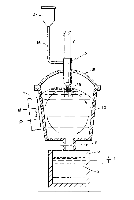
With reference to Figure 1, a crucible (10) suitably made of
graphite contains a molten metal bath (1) of matrix metal e.g.
aluminum which is stirred by way of a conventional magnetic
inductor 4 to physically agitate the metal bath (1), preferably in
the vigorous rotating motion shown in Figure 1. The crucible (10)
205~05
is provided with a protective cover (15) in which is installed an
ionization chamber (2) of extended length. Ihert gas, e.g. argon
is controllably introduced from lines (8) into ionization chamber
(2) and the gas is ionized to produce a plasma arc in accordance
with known techniques, and very high temperatures are developed in
the ionization chamber (2) ranging from 8000 deg. C to 20000 deg.C.
Finely divided filler material is held in hopper (3) with metering
means (not shown) for measuring the weight of finely divided
filler material which is introduced via conduit (16) into the
ionization chamber (2). The filler particles entering ionization
chamber (2) are rapidly heated to a high temperature below that at
which melting of the particles occurs, e.g. between 0.5 and 0.9 of
the melting point temperature of the particles. The thus heated
and activated particles entrained in a stream of the ionized inert
gas (25) are introduced into the molten bath (1) by injection of
the inert gas and penetration thereof below the surface of the
metal bath. The continuous physical agitation of the metal bath
(1) by magnetic inductor 4 establishes a uniform dispersion of the
solid heated activated filler particles. The temperature of the
metal bath is measured, e.g. by thermocouples (not shown) to ensure
that the temperature is below that at which undesirable melting or
decomposition of the filler particles occurs. Uniformity of
dispersion of the filler particles in the bath is established by
analyzing samples taken from bath at convenient intervals. When
the pre-determined desired amount of solid filler particles have
been introduced into the molten metal bath, plug ~5) at the base of
.
~0~160~
crucible (lO) is opened and molten metal containing the solid
additive particles (o) is introduced into mold (6) e.g. suitably
made of steel. The molten metal is caused to solidify in the mold
and surrounds the uniformly dispersed solid filler particles. To
ensure that the solid filler particles remain uniformly dispersed
in the molten metal phase as solidification progresses, an
ultrasound transducer (7) is coupled to mold (5) so that molten
metal in the mold is physically agitated by ultrasonic energy
vibrations until all of the molten phase has passed into the solid
state.
Figure 4(A) shows the crucible of Figure 1 provided with a
conduit (20) for introducing reactant into ionization chamber
(2') with an increased velocity of the ionized gas being indicated
at (25) resulting in deeper penetration of the additive into the
metal bath. Figure 4(B) shows the crucible of Figure 4(A) with
ionized gas and additive being introduced at the bottom of the
ladle. The inert gas forms bubbles (30) which are broken up and
dispersed by ultrasonic transducer (12) in contact with the upper
portion of the metal bath at its surface.
Figure 5 shows the crucible of Figure 4(B) with the ultrasonic
transducer (12) and the injection of ionized gas (25) being offset
~rom the central alignment of Figure 4(B) to achieve the
illustrated upwardly spiralling movement of the particle containing
bubbles (30).
18
-, . '',. .
, - ,. . ''.~,,,' ' . , ~
20~60~
EXAMPLE
For testing the method of the invention use was made of
unalloyed metals-aluminum and iron, as well as an aluminum base
alloy 4~Cu, 1.5% Mg, 0.5% Mn~ ~ ese materia~s were separately used
as the base melt for production of various composite materials.
The starting reinforcing materials used were powdered silicon
carbide, 5 - 50 micron in size, titanium aluminide TiAl3 with
particle size of 1-10 micron, and also titanium powder 10-loo
micron in size.
Tests to produce composite materials were run in the pilot
unit, shown schematically in Fig. 1. The crucible was made of
graphite and contained a matrix melt (1) which was injected with a
stream of ionized argon gas with entrained reinforcing particles
preheated to predetermined temperature by means of a conventional
plasmatron type ionization device (2) fitted with the metering
device (3) to establish a predetermined rate of powder flow through
the ionization device. The temperature of the particles, Tp was
varied and was monitored by detecting the change in neat content of
the base melt before and after injection of particles of powder.
Tp was calculated by the formula:
Tp= 6 m m (¦-- TDJ ( l + KN ) )
'
~ ,
- 20~160~
where: ~ - melt temperature after inject of additives, C;
T~ - matrix temperature before injection of additives, C;.
C~ - specific heat of matrix metal,
M~ - metal mass, K9
Cp - specific heat of particles, Mp - particles'
mas, Kg
Kn ~ dimensionless factor taking into account heat effects
upon air cooling of melt surface during preheating in
treatment by stream of ionized gas without
injection of particles, Kn = 0.05-0.06
for 5 Kg of molten metal and an
metal and an ionized argon gas flow of 0.1 M3/min.
Stirring the mix in the course of injection of additives
casting was accomplished by means of the magnetic inductor (4).
After injection of predetermined quantities of solid additives the
plug (5) was removed from the crucible and a liquids-solid mixture
~lowed through the hole in the crucible bottom to fill a casting
mold made of steel. The steel mold (6), 50 mm diameter, was used
and the molten metal-solid particle mix was stirred by ultrasound
generator (7) until the mold contents solidified. The resulting
solid casting of 2.5 kg. was hot extruded. Quality assessment of
resulting composite material was determining the following
parameters:
-chemical and structural uniformity,
-size of reinforcing particles,
-strength of composite material.
. . . .
. , : . . . . , ~,
,, ,
. ;- ,
2~5:~0~
Chemical non-unifcrmity of composite material was evaluated by
change in content of components of reinforcing particles in various
cross-sections of the casting across the casting direction by
determining the chemical non-uniformity factor K:
C ~ Cn~
C I ~ C
Where: Ck - content of components of reinforcing particles in
cross-section of the casting, wt. ~;
n - number of cross sections analyzed;
Cmax Cmjn - maximum and minimum content of components of
reinforcing particles in cross-sections, wt. %.
Structural non-uniformity of the composite material was
assessed by change of average sizes of reinforcing particles by the
factr Kave
the factor KaVe:
d ~i~
n ~1
Where d~ - average size of i-th particle, micron;
dmaX dmjn - maximum and minimum sizes of analyzed particles
n - number of analyzed particles. O
Strength was assessed by measuring the ultimate tensile
strength Rml MPa (UTS). Chemical composition was determined by the
quantimeter ARL 72000, with a precision of + 0.01%; structural
characteristics were determined by the metallographic optic
~0~160~
microscope MeF-3A at magnifications up to 3000X and the structural
analyzer Omnimet 2 for quantitative determination of elements in
the structure. Determination of strength was by the tensile
machine UTS-100 with maximum applied force of 100 KN. All of the
foregoing equipment is state-of-the-art. Table 1 shows the results
of the tests.
The resulting data proves that the best characteristics are
ensured by the samples of composite materials produced in the
experiments No. 6, 9, 12, 36, 42, 51, 57, 66, 69, 72 in accordance
with the method of the present invention for production of metal
base composite materials.
In a further embodiment of the present invention, filler
material for the making of a composite material is synthesized in
the environment of an ionized entraining gas and the thus produced
nascent materials, shielded by the cleaning ionized gas, are
introduced into the base metal melt which is physically agitated,
e.g. by magnetic and ultrasound techniques to uniformly distribute
the synthesized material in the base metal matrix. The filler
materials are synthesized by introducing substantially
stoichiometric amounts of the reactants for producing the filler
material. For example, in making titanium nitride filler material
titanium powder suitable sized 20-50 micron is entrained in
nitrogen gas in proportions corresponding to the equation:
2 Ti + N2 ----2 TiN
The titanium/nitrogen mixture is passed into a stream of
ionized inert gas and exposed to the ionized gas at a temperature
-~ , ; ;:
: .
. - ~ , -
20~60~
in the range of 2200-3000 degrees C for a time sufficient to
complete reaction between the titanium and nitrogen to form
titanium nitride in vapor form which is carried by the ionized
inert gas onto the surface of the base metal melt, e.g. aluminum,
which is physically agitated to unlformly disperse the titanium
nitride in small discrete volumes which, on solidification in the
base metal, provide ultrafine strengthening filler particles.
Other filler materials can be similarly synthesized as
follows:
3Si (powder) +2N2----Si3N4
Ti (powder) + 3Al (powder)----TiAl3
The temperature of the base metal melt is maintained at a
temperature which will quench the additive materials so that the
synthesized additive material is not undesirably dissolved in the
melt.
In another embodiment of the invention, a carbon bearing gas,
such as the hydrocarbons, propane, butane natural gas, methane, or
carbon monoxide, carbon dioxide are ionized in mixture with a
stream of ionized inert gas and dissociated. The carbon
dissociation product is monatomic elemental carban which is
in~ected into the base melt as a filler addition. For the oxygen
bearing gases, the liberated monatomic oxygen is an ionized gas
stream which reacts with the melt, e.g. aluminum, to form ultrafine
filler particles of aluminum oxide, Al2O3 in the melt.
Following the practice of the present invention under the
condition of Table 2 and using the materials of Table 2, the
~:
20al~0a
indicated additives were introduced into the indicated molten base
metal matrix to produce composite materials having improved
mechanical properties.
,~ ~ Cl~ O ~ r 1 O U'~ ON rl ,~ U') NO ~ O 0 2 ~ 5 1 6 0 5
X ~1 r~l rl rl N t`l ~ ~ ~ ~ N ~ ~ r~ ~1 1`~
t~ r~ N 01~ ` r
X a~ ~ ~ ~ o o o o o o o o o r~
U u~ O~
K to o o o o o o o o o o o o o o o
~o.~3lc~
1`.. O~0ococoo~
t: ~
O1
0~
O O t)
V)
~o ~
9 ~ ~
~ o
C ~ ~ 0 ~ ~ O ~ O ~ O ~ ~
ec~ r~ " ....... ~
&~
d
~'
s ~ -
.
'~5~ G' ' ~ ' .... s .,
D j; ~ o o o o o
~ U ~ O o o O o
14 OX '
2~ 6~
o o o o U~ U~ o U~ ~ U, ~ ~ ". .- o oo o '` -
oo ~O In
O O
oooooooooooo~oooooooo
o o u~ o un o o ~ u) o u~ o o o o r ~
.~
~o X Z':::::~::::::::: ,
S
~ ~ 1 l lo l ~ T ,, , ,, T ~o ~ ~o ~o ~ ol ~o
u~ o u~ o o ~ oO o ~ 00 00 ~ oO oO U- oO O In o ,~ 1
O, ~ ~ ~ : ::
~:::::::::~:::~ :::::
t~ r ~ :::::::::::
~ ~ o~:: tO:: ~ ~-1: ~
'I ;; ~ O O O O O O
~i ~ ~
O O O O O
~- oooo 2~5160~
O ~1 O N ~ N ~ 1~ U) O O a\ N CO ~ N (J~ ~ ~ N O ~0 ;
~0 ~D ~ ~ ~ ~ ~1 ~ N N N N ~' 1~ 1~ ~0 ~D `1:) U~ U~ U~ ~v
.... - - - ~
000000 000000000 .,
~ 7 ~ O ~ Iq o N ~ rl ~ ~ ~ ~1 ~ g ~ ~ O 1~ ~ O
a~ ooooooooooooooooooooo
r ~ ~ ~ ~ ~ ~ ~-~ ON ~`~ ~ N ~ a:~ a~ ~.~ I`
~O ~ Z U~ ~
~: a
u~ m E~ O 0~ 0 0 u) O 0 7 0l ~0 o7 O~ ~0 co~ O 0 00 0 ~0
o u~ o o ~ o o u~ o o o o o o o o o o o o o
~ ~ o o o~ ,ol ,o~ to o~ O co ,/ o~ x ,~ l
o o o o o o o
~ ~ ~ :: ~ S: ~ o
~, u~
~1 N
N '¢:: ;:::::: ~1:::::::::::
O~ o a~
o o o o o o o
N ~ ~D ~1 CO ' ~1
O O O O O O
.' X
.. ' rl ~ ~ ~ O 1 N t~
- oooooooooooooooooo~ 2~s~a~
O ~1 O ~ N O 10 0~ 0 ~ ~ O O ~ 0 ~1 rl
,/ ~ ~ ~r ~o ~ 'D ~ ~D r~ ~ t~ ~ r 1~ co
In In In U) Ul ~ O~ ~ ~ ~ O
0~ t`l ~ .~i ~ N ~`1 O O O O O O O O O ~`1
CO O~ ~ O
t~ ~ O ~D 1~ u~ In ~D ~1 ~r ~o ,~ ~ It7 ~ ~ Y ~
O O O O O o O o O O O O O O O O O
In U~ U~ O O O ~ 0
r/
.,~
Z
~D ~
O O O O O O o
u~ 0 o o a~ ~ o a~ o o c~ o o 01:~ 0 0 O~ O
O O I O O O O O O O I O O O o O O o
o a~ o o a~ o o tO o o CD p O C~ O O C~
r4 ~ ~ ~ ~
~r o o o o o o
o oo O ~r o o
~ S S~ :: 0:: ~
,~
~ u~ ~n
0: ~ o .: _ 5:: :
O O
U~
r~
~O
C~::~:::::~::::: : :
a~ ~ ~1 0 o~ ~
O ~1 ~ rl O O
: ~
O O O O O o
t`~ ~ r1 CO 11
O rl ~ O O O
~ ::: :: :: :: :: :: ,'
~ O O O O O O
~ 0 a) o r~
205160S `, I
+ + +
~1+
3~ ~ i~ I) N In N
~:
O
V ~ Z`~ Z
~u~ ~ o
~a e ~ O a
Vu'~ ~ ~O~ ~i o o ~i o o ~i 'a~ :
1~ .¢ ~ ~ O U~ ~ ~ O E~ ~ ~3 0 h ~ O
V a o o o
- ~ ~