Note: Descriptions are shown in the official language in which they were submitted.
CASE 3 7 7 4 ~5
~P~C~
Backaround and $umma~v o~.th~ Pre~çnt I~vention
The present invention relate~ generally to an
apparatus ~or macerating meat products to i~prove the
texture, water holding capacity and tendernes~ ther~o~.
More particularly, the present lnvention r~late~ to an
improved apparatus for macerating meat products by
passing the meat product~ through a pair of parallel
rotating shafts having radially extending teeth which
project into th~ meat and breaX up meat tissues.
It is well known that thQ water holding
capacity and the textural prop~rti~s o~ processed meat
;~ products can ~e greatly impro~d by macerating raw
materials prior to further proces3ing. ~ac~r tion
re~ults in the rupturing or tearing o~ the raw mat~rial
; 20 muscle fib~r~. This phy~ical action result3 in increased
protein solubilization and expose~ more surfac~ area or
'bindinq site~' ~or water ~ol~cul¢s. Af~er maceration,
the bonding ability of th~ muscls piece~ i~ al~o
~nhancQd, which allow~ maceratad meat product~ to be ~o:r~
ea~ily ~oined tog~thor, ~uch a~ by phy~ical pres3ur~, and
then sub~equently molded and cook~d.
Macera~ion eurther result~ in r~duc~d holding
ti~ fro~ the time o~ non-~eat ingr~dien~ addition to
cooking b~cau~e it incrsase~ the ~ur~ace area o~ the meat
product, which r~sults in d~p~r, mor~ rapid p~n~tration
and quick~r lntake o~ thes~ non-meat ingrQdlents into the
muscla fibers.
;~@1 5~
-2-
Many devices exist in the art ~or macerating
meat. Typically these macerating device~ include rotary
circular blades, radial tines, or relatively broad teeth
which are either mounted on a single shaft supported
above a meat-supporting or conveying table or which are
mounted on a pair of spaced-apart opposing rotating
shafts having a central gap therebetween t:hrough which
the m~at product passes. However, thesa clevices suffer
from certain disadvantage~. In one aspect, the
macerating rotating shafts are u~ually composed of a
plurality of macerating members and spacing co~ponentY
which are assembled onto a base shaft. The us~ of
multiple individual components increases the time and
ef~ort required to clean the macerating ~hafts because
the ~haft~ must be completely disassembled to ensur~ that
no meat juices or ti~SUQ remnant~ remain on any o~ the
components which would pose a bacteriological problem.
: In another aspect, where a stripper member or comb is
used with multi-component macerating shaft~ to remov~
msat from th~ intervening ~pace~ between the ~acerating
component~, th~ comb may tend to forc~ ti~sua re~nant~
into the space3 between th~ spacer and macerating
compon~nt~, thereby nece~eitating more frequent clQaning
of thQ macerating shafts.
Th~ pre~ent invention is d~rect~d to a
con~truction whlch avoid~ th~ aforementioned
di~advantagQ~. In a mac~rating apparatus con~tructed in
accordance wi~h the principles Or the pre~ent invention,
a pair o~ ro~atinq maceratin~ rollers or ~ha~ts ar~
dispo~d generally parallel to each other in a spaced-
apart relation~hip to dePine a gap therebetween through
which maat product~ are drawn. Th~ macerating ~ha~ts
each havs a ~orm~d one-piece arbor a~ixed to it, which
3.
-3-
arbor has a plurality of radially projecting macerating
portion~ or teeth which are disposed on ~he respective
longitudinal axes of the shaft~. Adjacent macerating
teeth are sepaxated by spacer portions which serve to
define a plurality of channels b~kween th~ macerating
teeth. The two macerating sha~ts are aligned in an
axially offset ~anner ~uch that th~ macerating teeth of
one shaft project into the channel~ o~ thl~ other shaft.
The maceratinq teeth are generally triangular in ~hape
and have respective meat contactinq and p~enetrating
peripheral edges. These p~ripher~l edge~ arQ axially
dir~cted and have a sufficient thickne~ ko effect
shallow penetration of the meat in the plane
perpendicular te the direction o~ travel of the meat
~ 15 through the macerator. The macerating teeth project only
:~ a short distance into th~ separating channel~ of the
opposing shaft so that a ~hallow~r penetration and
greater compres~ion of th~ m~at product i5 obtainedO The
one-piece con~truction o~ the macerating sha t arbor~
minimiz~ the cleaninq tim~ thereof and reduce~ the
likelihood o~ the accumulation of meat product ti~sues on
the arbors over time.
Accordingly, it i8 a general object of the
pre~ent invantion to provide an improved apparatus for
macerating meat product~ by pa~sing the meat product~
through a pair o~ counter-rotating oppo3ing macerating
shaft~
It i3 another ob~ect o~ the present invention
to provide an apparatus for macerating m~at produc~ by
passing the meat p~oducts through a pair v~ count2r-
; rotating maceratinq ~ha~ts, wherein each o~ th~
macerating sha~t~ includ2~ a one-piece arbor a~ixed
th~reto, each arbor having a plurality o~ radial rings
projecting outwardly and separated from each other by
spac~r portions.
Another object of th~ present invention is to
provide a macerator wherein the macerating sha~ts have a
plurality of macerating ring~ which project radially
outwardly from the shaft and wher~in the peripheral edges
of the macer~ting rings include a series of teeth having
a relatively sharp cutting edge disposed i.n an axial
plane parallel to that o~ the shaft.
Yet another object of the pre~ent invention is
to provide an improved macerator apparatu~ having
macerating shaft~ of substantially one-piece integral
construction which improve3 th~ sanitary characteristi~s
thereof.
: 15 It is yet another ob~ect o~ th~ present
invention to provide an apparatu~ fcr macerating m~at
product~ in which shallow pen~tr~tion of the meat i~
obtained in the axial plan~ of the meat product.
~nother object o~ the pre~ant inventioA is to
provide an improved ~acerator apparatu~ that ef~ects a
: superior crushing action as oppo~ed to a c~tting action
on the meat which crushing action result~ in finished
product color uni~or~ity ~nhancement which enhancement is
belieY~d to bo d~e to i~proved disper ion o~ heme
plgm~n~ re~ulting from increased call memhrane
disruption.
The~e and other ob~ects, featur~ and
advan~ages o~ th~ pr~sent invention will be clearly
und~rstood through a consid~ration or th~ following
detail~d description.
Bri~f Desc~in~iQn o~_th~ win~
In the course o~ thi~ description, re~rence
~ ~ 5 ~
will be made to the attached drawings, wherein~
Figure 1 is a perspective view of an apparatus
~or macerating meat products construct~d in accordance
with the principles of th~ present invention;
Figure 2 is a ~rag~entary elevation view o~ the
apparatus o~ Figure 1, illustrating the macerating
shafts;
Figure 3 i~ an elevational view of the
apparatus o~ Figure 1;
Figure 4 is a transverse cross-3ectional view
along the line 4-4 o~ Figura 3;
Figure 5 i~ an enlarged sectional view o a
portion of the macerating shaft3 shown in Figur~ 4; and
Figur~ 6 i~ a perspectiv~ view of a second
embodiment of a macerating sha~t.
Det~iled_Description of~e Preferred Em~odimen~
Figur~ 1 illustrates an apparatus 10 for
macerating meat product~. Included i an up3tanding
ZO frame 12 which is generally r~ctangular in for~. The
~rame 12, at it~ ~orward end, include~ a oonvQntional
food conveyor a~3embly 14 having a b~lt 16 and an
; as~ociated conv~yor drive mechani~m 18. The conveyor
bslt 16 is di~po~d within th~ outer member~ 100, 102 of
tho apparatus ~rama 12 and l~adR up to a pair o~
macerating rollers or sha~t~-20, 30. The macarating
shaft~ 20, 30 ara rotatably ~ount~d in cvnventional
bearings 40, 42 at th~ downstream and o~ the apparatus
~rame 10. The sha~ts 20, 30 are drivan in
countsrrotation, by conv~ntional driv~ mecha~i~m~ 44, 4
such as toothed b~lt~ or chaln drlve~, pr~erably in a
manner whereby the sha~t~ 20, 30 rota~a at tha sam~
speed.
-6-
The endless conveyor assembly 14 i~ provided
for supporting a meat product 7 thereon and delivering it
to the macerating shaft~ 20, 30. The conveyor belt 16 is
of conventional construction and may be formed from any
flexible material ~uitabl~ for u~e in food proc~s~ing
applications and either may be driven by an independent
drive mechanism 110 or may be driven by either of the
driv~ mechanisms 44, 46 associated with thQ macerating
sha~ts 20, 30. In either instance, it is preferable to
hav~ the speed of the conveyor belt 16 synchronized with
the speed o~ the macerating shaft~ 20,30.
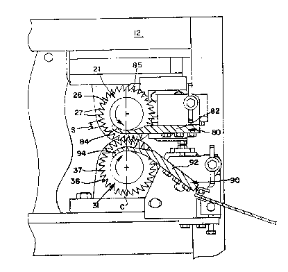
Each macerating shaft 20, 30 include an
elongated arbor 21, 31 which generally span~ the width of
the apparatu~ frame 12. The arbors 21, 31 may be ~or~ed
a~ an integral sleeve with a central cavity 70 extending
therethrough ~Figure 6) which cavity 70 i~ adapted to
receive the respective first and second drive shafts
therein. Alternatively, as shown in Figure~ 3-5, the
arborc 21, 31 may be sub~tantially ~olid in cro~s-section
and may include at lea~t one hub portion 50, 60 dispo ed
at an end ther~o~. Th~ arbor hub portion~ 50, 60 o~ each
arbor contain generally central cavities 51, 61 which are
adapted to engag~ driv~ ~hafts 52, 62. Th~ end oppo~ite
the hub portion~ ~erva a~ spindle~ 5~, 64 which ar~
rotatably mounted on the appara~us frame. The macerating
arbor3 21, 31 wh~ch ar~ driv~n by th~ shafts 20, 30 are
ad~u~tably mount~d on th~ apparatu~ fra~e 12 ~o that t~l3
gap 200 present between the arbor~ 21, 31 can bo ad~usted
in accordance with the m~at to b~ proce~sd by the
apparatu~.
As shown in the preferred ~mbodi~nts depictQd
in the Figure~, each arbor 21, 31 is Or integral
construction and thu~ ormed ~ro~ a ~ingle piece of
metal. ~ach arbor 21, 31 ha~ a series of alternating
radially proiecting portions 22, 32 which are equally
spaced along the longitudinal axi~ of the respective
arbor. The radially projecting portions 22, 32 have a
first diameter ~. (Figuxe 2) The radially projecting
portlons 22, 32 are s~parated by spaced-apart portions
23, 33 having a second diameter B which i~ less than the
first diameter A of the radially projecting portion~ 22,
3~. The axial spacing of the first and s~cond arbor
spaced-apart portions 22, 33 between the radially
projecting portions 22, 32 i5 greater than the axial
length o~ the teeth of the ~irst and ~econd arbor
radially projecting portions 22, 32 ~uch that a series of
open or crushing channels 25, 35 are de~ined by the
opposing sidewall sur~aces of adjacent radially
: projecting portion~ 22, 32 and the axial length of the
separating, intervening spac~d-apart portion~ 23, 33.
Th~ f~rst and s~cond arbore 21, 31 ar~ ~ounted
in alignment on their respective mac~rating sha~ts 20, 30
such that, a~ they rotate in oppo~ite direction~, the
radially pro~cting and axially extending portions 22 o~
the fir~t ~ha~t 20 are aligned with th~ open channel~ 35
formad by th~ ~paced~apart portion~ 33 o~ the second
shaft 30. Lik~wi~, the radially projecting and axially
extending portion~ 32 o~ the second shaft 30 are aligned
with the open channels 25 ~ormed by th~ ~paced-apart
portion~ 23 of its opposing fir~t sha~t 20.
Additionally, th~ Sir~ and sacond arbor~ 21, 31 ar~
~urther aligncd and synchronized so that, in operation,
the ra~ial teQ~h peripheral edges o~ one arbor pas~
through the center point ~ o~ th~ ~pacing ~ betwQen
succesaive radial teeth on the oppo~ing arbor (Figuro 5~.
AA shown mor~ clearly in Figure 5, each ~irst
$'i.~
-8-
and second arbor~ radially projecting portions 22, 32
include a plurality of radially projecting teeth 26, 36
having a preselected axial length. The integral teeth
26, 36 have a generally triangular profile when viewed
from the side wherein each individual tooth b~gin~ with a
relatively thick base portion 85 near the second diameter
~ of the respective arbor and extend~ radially outwardly
to terminate in a narrow, axial meat cont,~cting ~ur~ace .
or edge 27, 37 at thQ apex of the triangular profile.
The forward edges 125 of each o~ the teeth are generally
arcuate whils the trailing edges 127 ars substantially
planar (Figur~ 5~. Successive teeth on each arbor
radially projecting portion are sub~tantially eq~ally
oircumferentially ~paced-apart with a uniform spacing 8.
The radially proje¢ting teeth 26, 36 ~ay be
form~d on their respective arbor~ by conventional
machining euch that they are inteyral with the arbor~,
thereby reducing ths likelihood of the b~nding or
breaking of the teeth driving maceration. In an
important a~pect o~ the pre~ent invent~on, the axial
length~ of ~he~ meat contacting surface~ or edge~ 27, 37
are pre~erably les~ than ths axial length o~ the channel~
25, 35 ~ormed by th~ arbor ~pac~r portions b~twean
adjoininq pro~ct$ng portions ~o that the teeth are free
to pas~ through tho channels 25, 35 and so that tha teeth
effect pri~arily ~ cru~hing action on th2 meat product~
passed ther~thxough rather than a cuttin~ ac~ion. ~n
thi~ regard, a tooth axial length o~ 0.25 inche~ or less,
pre~erably about 0.220 inch~s and a spacsr portion or
channel axial length o~ greatar than 0.25 inches,
pre~erably about 0.280 inche3. It is ~urther dasirabl~
to have an equal clearance present on both ~ide~ of the
teeth o~ approximately 0.030 inche~ ~or th~ purpose$
- 9~
explained more fully below.
The radial extent of the macerating teeth 26,
36 i~ such that the meat contacting sur~aces 27, 31
preferably project into the open channels 25, 35 for no
more than hal~ of their radial extent. Il1 this regard, a
radially projecting extent of approximately 0.375 inches
for each tooth wlth a corresponding tooth projection
distance o~ approximately 0.187 inch~s ha~ been found to
give prQferred result~. It will be undsr~tood however,
that where poultry product~, ~uch a~ turkey, ar~ used
with the present invention, thesQ distances will increase
such that the distanc~ b~tween the two arbors is greater
to accordingly reflect the difference in the typical
thicknes~ of the product passed between the arbor~.
Such a construction ha~ been found to giv~
unexpected benef it8 . When th~ meat product~ are pa~secl
through the gap 200 present betwe~n the ~acerating shafts
20, 30, the meat i~ contacted by the r~dial te~th 26, 36
which penetratQ it via th~ axial meat contacting sur~ace~
27, 37 at the outQr~ost extQnt thereof. A~ the
macQrating shaft~ 20, 30 continue to rotate, tha meat is
pres~ed into the oppo~ing arbor opQn channels 25, 35 by
the radial te~th and co~pr~Qd against the arbor spaced-
: apart portions 23, 33 to effect crushing of th~ meat
ti~ue~. Becaus2 o~ the relatively shallow penatration
of the radial teeth 26, 36, i.~. onQ-half or les~ of the
depth o~ the cru~hing chann~l~ 25, ~5, more crushing or
compres~ing o~ th~ m~at produc~ i~ obtainQd rathar than
cutting, rQsulting in o~Qrall enhanaed product coloration
uni~ormly and water holding capacity o~ th~ product~
pas~d betw~en the arbors.
Individual comb~ 80, gO a~sociated w~th ~ach o~
tha first and second mac~ratinq ~ha~t3 20, 30 ara
-la-
provided to assist in stripping the macerated meat
products from the macerating shaft~. Each comb 80, 90 is
preferably mounted at its oppo~ite ends on the apparatus
~rame and extend~ tran~verse to the direction o travel
of the conveyor belt 16 and parallel to the longitudinal
axes of the macerating shafts 20, 30. Each co~b has a
body portion 82, 92 and a plurality o~ individual
extension~ or side tine~ 84, 94 which extend betwe2n the
radlally projecting portions 22, 32 of the first and
second arbors 21, 31 and abut the interven~ng spaced-
apart portion~ 23, 33 at ths top and bottom of the gap
200 between the macerating shaft~ 20, 30. The tineg 84,
94 extend past the centerlin~ C of the two arbors~
It will be noted that the prQ3ent invention
provides unique advantageR in that thQ onQ-piece,
integral construc~ion of the two macerating ar~ors
improves the sanitary and efficiency characteristic of
such apparatus because th~ tim~ reguired ~or cleaning the
macerating element~ i3 reducQd as~ compared to multi-
component macerating elem~nt~ and also because there are
no mating ~ur~ac~ into which meat tissue re~nant~ and
juice~ can flow~ Th~ one-piQce integral con~truction and
the ~acerating teeth proSile~ also serv~ to prevent t~e
breaking o~ the tQath during macerating operat~on~.
Moreover, becauss the axial spacing o~ th~ arbor ~paced-
apart portion~ 23, 33 is greater than th~ axial length o~
th~ arbor radially projec~ing teeth 26, 36 and becau~ of
the axial alignm0nt o~ the ~irst and second arbor~, a
soissor~-typ~ macerating ac~ion is obtained, thereby
r~sulting in more crushing o~ the meat product against
the spac~d-apart portions 23, 33 rathor than cuttinq o~
th~ meat product by the radlally pro~c~ing portions 22,
32. In this ~cis~ors-type macerating activn; th~ radial
teeth of one arbor project no more than halfway into the
corresponding open channel of th~ other arbor and wherein
as shown in Figure 5, the teeth of one arbor will
~ub~tantially rotate in the center o~ the successive
teeth spacing, ~ of the other roller.
It will be seen that while certain embodiments
of the present invention hav~ been shown and described,
it will be obvious to those skilled in the art that
changes and modifications may be made therein without
departing ~rom the true spirit and scope of the
invention.