Language selection

Search

Patent 2051940 Summary

Third-party information liability

Some of the information on this Web page has been provided by external sources. The Government of Canada is not responsible for the accuracy, reliability or currency of the information supplied by external sources. Users wishing to rely upon this information should consult directly with the source of the information. Content provided by external sources is not subject to official languages, privacy and accessibility requirements.

Claims and Abstract availability

Any discrepancies in the text and image of the Claims and Abstract are due to differing posting times. Text of the Claims and Abstract are posted:

  • At the time the application is open to public inspection;
  • At the time of issue of the patent (grant).
(12) Patent: (11) CA 2051940
(54) English Title: MANUAL IMPLEMENT HANDLE ATTACHMENT
(54) French Title: MANCHE AUXILIAIRE
Status: Expired and beyond the Period of Reversal
Bibliographic Data
(51) International Patent Classification (IPC):
  • B25G 1/00 (2006.01)
  • A01B 1/00 (2006.01)
  • A46B 17/02 (2006.01)
  • A47L 13/00 (2006.01)
  • B25G 1/04 (2006.01)
(72) Inventors :
  • BECKINGHAM, DARYL (Canada)
(73) Owners :
  • DARYL BECKINGHAM
(71) Applicants :
  • DARYL BECKINGHAM (Canada)
(74) Agent: BATTISON WILLIAMS DUPUIS
(74) Associate agent:
(45) Issued: 2002-01-29
(22) Filed Date: 1991-09-20
(41) Open to Public Inspection: 1993-03-21
Examination requested: 1998-09-21
Availability of licence: N/A
Dedicated to the Public: N/A
(25) Language of filing: English

Patent Cooperation Treaty (PCT): No

(30) Application Priority Data: None

Abstracts

English Abstract


An auxiliary handle is provided for manual implements like rakes and
brooms. The handle has a lateral arm with one end pivotally connected to the
implement handle by a clamp and the opposite end connected to an upright
second
arm, which is in turn pivotally connected to the implement handle by a clamp.
The
upright second arm is telescopically adjustable in length to allow the system
to be
adjusted to suit most any implement configuration and personal stature. The
lateral
arm is also preferably telescopically adjustable. It carries one or more hand
grips.


Claims

Note: Claims are shown in the official language in which they were submitted.

-6-
CLAIMS
1. An auxiliary handle for a manual implement having a working head and
an elongate implement handle, said auxiliary handle comprising:
a lateral first arm with first and second ends;
first clamp means pivotally connected to the first end of the first arm and
adapted to be clamped to the implement handle;
an upright second arm with first and second ends, the second arm
comprising telescopic means for altering the length of the second arm and lock
means
for locking the telescopic means for selectively and temporarily fixing the
length of the
second arm;
pivot means pivotally connecting the second end of the first arm to the
second end of the second arm;
second clamp means pivotally connected to the first end of the second
arm and adapted to be releasably secured to the implement handle; and
hand grip means mounted on the first arm.
2. An auxiliary handle according to Claim 1 wherein the first arm comprises
telescopic means for altering the length of the first arm and lock means for
locking the
telescopic means for selectively and temporarily fixing the length of the
second arm.
3. An auxiliary handle according to Claim 2 wherein the hand grip means
comprise a handle loop and handle clamping means for releasably clamping the
handle loop to the first arm.
4. An auxiliary handle according to Claim 3 wherein the hand grip means
include pivot means for pivotally mounting the handle loop on the handle clamp
means.
5. An auxiliary handle according to Claim 4 wherein the hand grip means
include a substantially tubular element mounted on the first arm.

-7-
6. An auxiliary handle according to Claim 5 further including tubular grip
means for engagement on the implement handle.
7. A manual implement comprising from: a working head; an elongate
implement handle; an auxiliary handle mounted on the implement handle, said
auxiliary handle comprising:
a lateral first arm with first and second ends; first clamp means pivotally
connected to the first end of the first arm and clamped to the implement
handle;
an upright second arm with first and second ends, the second arm
comprising telescopic means for altering the length of the second arm and lock
means
for locking the telescopic means for selectively and temporarily fixing the
length of the
second arm;
pivot means pivotally connecting the second end of the first arm to the
second end of the second arm; second clamp means pivotally connected to the
first
end of the second arm and clamped to the implement handle; and
hand grip means mounted on the first arm.
8. A manual implement according to Claim 7 wherein the first arm
comprises telescopic means for altering the length of the first arm and lock
means for
locking the telescopic means for selectively and temporarily fixing the length
of the
second arm.
9. A manual implement according to Claim 8 wherein the hand grip means
comprise a handle loop and handle clamping means for releasably clamping the
handle loop to the first arm.
10. A manual implement according to Claim 9 wherein the hand grip means
include pivot means for pivotally mounting the handle loop on the handle clamp
means.
11. A manual implement according to Claim 10 wherein the hand grip

-8-
means include a substantially tubular element mounted on the first arm.
12. A manual implement according to Claim 11 further including tubular grip
means for engagement on the implement handle.

Description

Note: Descriptions are shown in the official language in which they were submitted.


CA 02051940 2001-02-16
MANUAL IMPLEMENT HANDLE ATTACHMENT.
The present invention relates to implement handles and more
particularly to auxiliary handles for manual implements with elongate handles,
for
example rakes or brooms.
In the use of such manual implements as push brooms, rakes and
others with long, straight handles, it is often necessary for the user to
adopt a posture
or a hand grip that is uncomfortable and difficult to maintain for any length
of time.
While several attempts have been made in the past to provide auxiliary handle
system
on shovels to assist in lifting loads, these handles are not readily adaptable
to a range
of implements or for use by persons of different statures. They are not
especially
suited for use with implements where the primary action is not a lifting
action but more
a sweeping action, as for example with rakes and brooms. There is therefore a
need
for an apparatus for use with manual implements that is applicable to a wide
variety of
implements, for example rakes and brooms, for the appropriate manipulation of
those
implements by most persons.
According to one aspect of the present invention there is provided an
auxiliary handle for a manual implement having a working head and an elongate
implement handle, said auxiliary handle comprising:.
a lateral first arm with first and second ends;.
first clamp means pivotally connected to the first end of the first arm and
adapted to be clamped to the implement handle;.
an upright second arm with first and second ends, the second arm
comprising telescopic means for altering the length of the second arm and lock
means
for locking the telescopic means for selectively and temporarily fixing the
length of the
second arm;.
pivot means pivotally connecting the second end of the first arm to the

CA 02051940 2001-02-16
:2-
second end of the second arm;.
second clamp means pivotally connected to the first end of the second
arm and adapted to be releasably secured to the implement handle; and.
hand grip means mounted on the first arm.
The lateral first arm may be grasped in both hands and moved from side
to side in a horizontal movement without twisting or bending of the user's
back, thus
minimizing strain on the back, the shoulders and the arms.
The clamps and the adjustable, telescopic upright arm of the auxiliary
handle allow the lateral arm to be positioned at almost any desired height
above the
implement head and at most any desired orientation. Thus, regardless of the
nature
of the implement, the first arm may be positioned at a horizontal orientation
and at a
level that is comfortable for most any user.
Even greater flexibility is obtained if the first arm is also telescopically
adjustable and the hand grip is adjustable along and rotatable with respect to
the first
arm.
The invention also provides for an implement with the auxiliary handle
attached.
In the accompanied drawings, which illustrate an exemplary
embodiment of the present invention:.
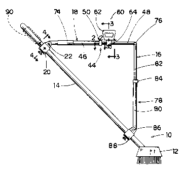
Figure 1 is an elevation of one embodiment of the invention attached to
a broom;.
Figure 2 is a cross section along line 2--2 of Figure 1;
Figure 3 is a section along line 3--3 of Figure 1; and
Figure. 4 is a section along line 4--4 of Figure 1.
Referring to the accompanying drawings, especially to Figure. 1, there is
illustrated an implement 10, in this case a broom, having a head 12 and an
elongate,

CA 02051940 2001-02-16
3-
cylindrical handle 14 sloping upwardly from the head. Auxiliary handle 16 is
mounted
on the implement handle 14 to make the implement easier to use.
The auxiliary handle 16 includes a lateral arm 18 affixed to the
implement handle 14 by a clamp 20 to which the arm is connected by a pivot 22.
The
pivot includes a pair of lugs 24 on the clamp and a pin 26 through the lugs
and the
flattened end 28 of the arm 18, which extends between the two lugs 24. The
main
body of the clamp is a ring 30 with a centre opening 32 that fits over the
implement
handle 14. A clamp plate 34 is positioned in the opening on one side and is
rotatable
on a stud 36 fastened to the end of a screw 38 engaged in a radial threaded
bore 40
in the ring 30. The screw 38 has a knurled head 42 so that it can be turned by
hand.
The arm 18 includes a telescopic joint 44. This includes an outer tube
46 and an inner tube 48 sliding in the outer tube. A lock 50 locks the tubes
together
at any desired position.
The lock 50 includes a thread 52 on the outer end of the outer tube 46
and an inwardly tapering bevel 54 on the inner surface of that tube. A ring 55
slides
on the inner tube, beyond the end of the outer tube and has a bevelled end 56
confronting the bevel 54 on the outer tube. The bevelled end is divided by a
series of
axial slots into a set of wedges 57. A thimble 58 engages over the ring 55 and
is
threaded onto the end of the outer tube. By turning the thimble onto the outer
tube,
the ring 55 is forced into the bevelled end of the outer tube, which forces
the wedges
57 into frictional engagement with the inner tube, thus locking the inner and
outer
tubes together.
The arm 18 also carries a hand grip fi0. The grip includes a hand loop
62 mounted on a clamp 64 by a pivot 66. The pivot includes a stud 68 fixed to
the
clamp and extending through a hole in the handle loop. The clamp is a
resilient split
clamp that is fastened to the arm 18 by a screw 70 and a wing nut 72 for
drawing the

CA 02051940 2001-02-16
:4-
arms of the clamp together around the arm 18.
Also mounted on the arm 18 is a tubular grip 74. This is a tube of
resilient material that provides a comfortable hand grip for a user.
The end of the arrn 18 opposite the clamp 20 is connected by a pivot pin
76 to a second arm 78 that extends vertically downwards from the pivot. The
second
arm is also telescopically adjustable using a telescopic coupling between an
outer
tube 80 and an inner tube 82 with a lock 84 that is the same as the lock 50 of
the first
arm. At the lower end of the arm 78 it is fastened by pivot 86 to a clamp 88
that is the
same as clamp 20 previously described. The clamp 88 is fastened on the
implement
handle 14.
With the implement handle described above, it is possible to adjust the
handle to suit almost any implement to any person. It is simply necessary to
release
the two locks 50 and 84, to fit l:he clamps 20 and 88 onto the implement
handle and
then to adjust the arm lengths and clamp positions to those desired by the
user. With
the push broom implement illustrated and the first arm horizontal, the first
arm may be
gripped in both hands and a sweeping action produced by a simple horizontal
movement of the hands. It is no longer necessary for the user to bend over to
place
one of the hands on a sloping handle at a lower position than the other. The
rotatable
loop handle may be attached to the first arm and oriented as desired for the
comfort of
the user.
Where desired, the implement handle 14 may be equipped with an
auxiliary hand grip 90 at its upper end. This may be a resilient tube much
like the grip
74 on the lateral arm of the auxiliary handle.
While one embodiment of the present invention has been described in
the foregoing, it is to be understood that other embodiments are possible
within the
scope of the invention. The invention is to be considered limited solely by
the scope

-5-
of the appended claims.

Representative Drawing
A single figure which represents the drawing illustrating the invention.
Administrative Status

2024-08-01:As part of the Next Generation Patents (NGP) transition, the Canadian Patents Database (CPD) now contains a more detailed Event History, which replicates the Event Log of our new back-office solution.

Please note that "Inactive:" events refers to events no longer in use in our new back-office solution.

For a clearer understanding of the status of the application/patent presented on this page, the site Disclaimer , as well as the definitions for Patent , Event History , Maintenance Fee  and Payment History  should be consulted.

Event History

Description Date
Time Limit for Reversal Expired 2007-09-20
Letter Sent 2006-09-20
Inactive: IPC from MCD 2006-03-11
Appointment of Agent Requirements Determined Compliant 2005-05-18
Inactive: Office letter 2005-05-18
Revocation of Agent Requirements Determined Compliant 2005-05-18
Appointment of Agent Request 2005-04-25
Revocation of Agent Request 2005-04-25
Inactive: Agents merged 2004-04-01
Grant by Issuance 2002-01-29
Inactive: Cover page published 2002-01-28
Pre-grant 2001-11-01
Inactive: Final fee received 2001-11-01
Letter Sent 2001-05-23
Notice of Allowance is Issued 2001-05-23
Inactive: Approved for allowance (AFA) 2001-05-02
Appointment of Agent Requirements Determined Compliant 2001-03-13
Inactive: Office letter 2001-03-13
Revocation of Agent Requirements Determined Compliant 2001-03-13
Appointment of Agent Request 2001-02-16
Amendment Received - Voluntary Amendment 2001-02-16
Revocation of Agent Request 2001-02-16
Inactive: S.30(2) Rules - Examiner requisition 2000-10-26
Inactive: Status info is complete as of Log entry date 1998-10-09
Letter Sent 1998-10-09
Inactive: Application prosecuted on TS as of Log entry date 1998-10-09
All Requirements for Examination Determined Compliant 1998-09-21
Request for Examination Requirements Determined Compliant 1998-09-21
Application Published (Open to Public Inspection) 1993-03-21

Abandonment History

There is no abandonment history.

Maintenance Fee

The last payment was received on 2001-09-20

Note : If the full payment has not been received on or before the date indicated, a further fee may be required which may be one of the following

  • the reinstatement fee;
  • the late payment fee; or
  • additional fee to reverse deemed expiry.

Please refer to the CIPO Patent Fees web page to see all current fee amounts.

Fee History

Fee Type Anniversary Year Due Date Paid Date
MF (application, 6th anniv.) - small 06 1997-09-22 1997-09-09
MF (application, 7th anniv.) - small 07 1998-09-21 1998-09-15
Request for examination - small 1998-09-21
MF (application, 8th anniv.) - small 08 1999-09-20 1999-09-14
MF (application, 9th anniv.) - small 09 2000-09-20 2000-09-15
MF (application, 10th anniv.) - small 10 2001-09-20 2001-09-20
Final fee - small 2001-11-01
MF (patent, 11th anniv.) - small 2002-09-20 2002-09-20
MF (patent, 12th anniv.) - small 2003-09-22 2003-09-10
MF (patent, 13th anniv.) - small 2004-09-20 2004-09-20
MF (patent, 14th anniv.) - small 2005-09-20 2005-09-13
Owners on Record

Note: Records showing the ownership history in alphabetical order.

Current Owners on Record
DARYL BECKINGHAM
Past Owners on Record
None
Past Owners that do not appear in the "Owners on Record" listing will appear in other documentation within the application.
Documents

To view selected files, please enter reCAPTCHA code :


To view images, click a link in the Document Description column. To download the documents, select one or more checkboxes in the first column and then click the "Download Selected in PDF format (Zip Archive)" or the "Download Selected as Single PDF" button.

List of published and non-published patent-specific documents on the CPD .

If you have any difficulty accessing content, you can call the Client Service Centre at 1-866-997-1936 or send them an e-mail at CIPO Client Service Centre.


Document
Description 
Date
(yyyy-mm-dd) 
Number of pages   Size of Image (KB) 
Cover Page 1993-12-03 1 13
Abstract 1993-12-03 1 13
Description 1993-12-03 4 145
Claims 1993-12-03 3 72
Drawings 1993-12-03 2 39
Drawings 1998-10-29 2 41
Drawings 2001-02-16 2 43
Description 2001-02-16 5 179
Abstract 2001-02-16 1 16
Claims 2001-02-16 3 88
Cover Page 2002-01-03 1 35
Representative drawing 2002-01-03 1 10
Representative drawing 1998-08-31 1 13
Reminder - Request for Examination 1998-05-21 1 117
Acknowledgement of Request for Examination 1998-10-09 1 177
Commissioner's Notice - Application Found Allowable 2001-05-23 1 164
Maintenance Fee Notice 2006-11-15 1 173
Fees 2003-09-10 1 33
Correspondence 2001-02-16 1 24
Correspondence 2001-03-13 1 8
Correspondence 2001-03-13 1 10
Correspondence 2001-11-01 1 39
Correspondence 1992-02-11 3 71
Fees 1995-10-25 2 45
Correspondence 2005-04-25 2 55
Correspondence 2005-05-18 1 13
Correspondence 2005-05-18 1 15
Fees 1996-08-27 1 49
Correspondence 1996-03-27 1 50
Fees 1996-03-14 2 68
Fees 1994-09-01 1 36
Fees 1993-08-26 1 28