Language selection

Search

Patent 2052091 Summary

Third-party information liability

Some of the information on this Web page has been provided by external sources. The Government of Canada is not responsible for the accuracy, reliability or currency of the information supplied by external sources. Users wishing to rely upon this information should consult directly with the source of the information. Content provided by external sources is not subject to official languages, privacy and accessibility requirements.

Claims and Abstract availability

Any discrepancies in the text and image of the Claims and Abstract are due to differing posting times. Text of the Claims and Abstract are posted:

  • At the time the application is open to public inspection;
  • At the time of issue of the patent (grant).
(12) Patent Application: (11) CA 2052091
(54) English Title: PUMP AND MEASURING DEVICE FOR COFFEE MACHINES
(54) French Title: POMPE ET DISPOSITIF DE MESURE POUR MACHINES A CAFE
Status: Deemed Abandoned and Beyond the Period of Reinstatement - Pending Response to Notice of Disregarded Communication
Bibliographic Data
(51) International Patent Classification (IPC):
  • A47J 31/46 (2006.01)
  • A47J 31/40 (2006.01)
(72) Inventors :
  • BIANCO, CARLO (Italy)
(73) Owners :
  • RICERCA ELECTTROMECCANICA S.R.L.
(71) Applicants :
  • RICERCA ELECTTROMECCANICA S.R.L. (Italy)
(74) Agent: ROBIC AGENCE PI S.E.C./ROBIC IP AGENCY LP
(74) Associate agent:
(45) Issued:
(22) Filed Date: 1991-09-24
(41) Open to Public Inspection: 1992-07-26
Availability of licence: N/A
Dedicated to the Public: N/A
(25) Language of filing: English

Patent Cooperation Treaty (PCT): No

(30) Application Priority Data:
Application No. Country/Territory Date
MI91 U 000064 (Italy) 1991-01-25

Abstracts

English Abstract


ABSTRACT
The invention is of a pump for coffee machines which
simultaneously carries out the functions of water measurer
and heater.
The pump consists of a cylinder with a piston inside which
sucks the water from a tank and directs it towards the
devices it serves, and in which there are electronic devices
for the control of the run of the piston and the consequent
measurement of the water.
Heating takes place by way of a resistance coiled around the
cylinder jacket with the whole in turn enveloped by an
insulating covering.


Claims

Note: Claims are shown in the official language in which they were submitted.

CLAIMS
1. A measuring pump for small electrical household
appliances distinguished by the fact that a cylinder is
provided on the inside of which runs a piston which sucks a
liquid through a feed duct and expels it along an exit duct
in which there are devices for controlling the run of the
piston in order to measure out the quantity of liquid.
2. A measuring pump as described in claim 1, characterized
by the fact that it is provided with a screw and/or
circulating ball actuator for controlling movements of the
piston shaft.
3. A measuring pump as described in claim 2, characterized
by the fact that the piston shaft is threaded externally and
forms the moving unit of the circulating ball actuator.
4. A measuring pump as per claims 1 and 3 with microswitches
activated by parts connected to said piston to bring it to a
halt.
5. A measuring pump as per claims 1 and 3, characterized by
the fact that the starter motor of said linear screw and/or
circulating ball actuator is a continuous current motor
controlled by an encoder.
6. A measuring pump as per claims 1 and 3, characterized by
the fact that the actuator starter motor is a stepper motor.

7. A measuring pump as per the preceding claims,
distinguished by the fact that it has an electrical
resistance coiled around the covering of said cylinder for
heating the water.
8. A measuring pump as per claim 7, characterized by the
fact that the external surface of said cyclinder is anodised
to insulate it electrically.
9. A measuring pump as per the previous claims characterized
by the fact that it has a layer of thermoinsulating material
around the cylinder and the resistance.
10. A measuring pump as described and illustrated.

Description

Note: Descriptions are shown in the official language in which they were submitted.


2052091
PUMP AND MEASIJRING DEVICE FOR COFFEE MAC~IINES
This new invention proposes a pump and measuring device for
coffee machines in particular which uses electronics to
control the movement of the pump piston and which at the
same time measures out the water amount. More precisely,
the pump is made of a cylinder with a piston inside which
sucks the water from a tank and pumps it along an exit duct.
These movements are controlled by an electronic or
electromechanical device for measuring the exact amount of
water to be pumped.
The device is particularly useful for small household
electrical appliances, especially - though not exclusively -
in coffee machines, allowing the machine to be made smaller
and costing less to rroduce.
Small electrical bousehold appliances are well-known in
which there is a device for pumping liquid that can also
measure out the quantity of liquid pumped and heat it up.
In these machines the various devices are autonomous and
separate, particularly the pumping and measuring parts.
Thus, for example, pumping may occur through a membrane pump
wlth the water lleated and measured out externally.
This means that the output has to be controlled ~y the user
or by a separate measuring device. The problems this causes
are then refLected in the price and the size of the machine,
both of which it would be beneficial to reduce.
o
, 6
.~
. _._ _, . _ .. .. __ _. _ _ . ., _. _ .... _ _, ... _ .. _.. _ __ ~_ _ . _ ., .. _ . . _ _ . _,, ., ... , . _ .. ., . _ .. .. ... _ .... .
_ .. , _ . , . . _ . , . _.. _ .. __ _ _ . . _. _ .. _ __ .
:~,"'
~ . .
'
, '

20~2091
Thus the new method involves a measuring pump for cof~ee
machines in particular which pumps, measures and heats the
water.
This new measurer has at least one cylinder body with a
piston moving inside, controlled electronically, for precise
measurement of the amount of liquid sucked up and pumped
out.
There follows a detailed description giving a general
example of the device with reference to the drawings
enclosed:
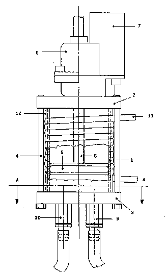
- Figure 1 is a vertical section of tlle pump and measurer
according to the invention;
- Fig. 2 is a section along the line A-A in fig.1.
With reference to the drawings, the device is basically made
up of a cylinder (1), closed at the top by walls (2) and
(3), fixed by a brace (4) or a similar structure, and with a
plston running inside (5).
The piston (5) movements are controlled by an actuator(6)
powered by a motor (7) which acts on the piston shaft (8).
Preferably the actuator (6) should be a circulating ball
screw type wlth the moving part being the appropriately
.~
threaded piston shaft. Control of the shaft (8) movement
will depend on the components used: microswitches at
I ~ :
different points may be used, intercepted by the shaft and
connected to the machine control devices; alternatively the
~ ~ .
'~ ~
.
" , .

20~2091
motor (7) may be a stepper motor controlled electronically
or a simple continuous current motor.
In this latter case the motor is linked to an encoder (not
shown in diagram) which controls the rotation of the motor
and the movements of the shaft (8) and thus the piston (5).
In the lower head wall (3) of the pump two attachments are
found (9 and 10). The first has a valve which allows the
passage of a fluid into the cylinder and is connected to a
water tank. The second is a delivery attachment with a valve
of a well-known type which allows the fluid to come out.
The cylinder (1) will preferably be anodised on its external
surface so as to be insulated electrically and with a
resistance coiled around it made of, for example, a number
of turns of nickel-chrome (11).
I
Preferably the cylinder with the resistance will then be
covered in a layer (12) of appropriate thermoinsulating
materlal.
From this description use of the device should also be
clear. ~ ~
t ~ Once the volume of water to be used has been determined, the
motor (7) is started which also starts the actuator (6)
~ ; which moves shaft (8) upwards with the piston (5).
; The distance of the movement, which is a function of the
volume of water sucked, is controlled by either
microswitches or encoders connected to the motor, depending
''
'- ' '~ ' ' .
' ,` . .
,. . .
. ~' .

2~2091
on the type of device used.
Once the necessary volum~ of water has been sucked the
resistance (11) is powered up until the required
temperature is reached after which the motor (7) is
activated to turn in the opposite direction, pumping the
water through the exit duct (10).
During the suction phase the return prevention valve in the
exit duct (10) remains closed whilst during the pumping
phase the valve in the suction duct is closed.
The measuring device described has various advantages, the
main one being that it is extremely compact. This means that
the amount o~ water used can be set previously and measured
out automatically, thus eliminating the need to use a
separate measuring device and allowing the pumping,
measuring and heating units to be enclosed in a single
block.
The unit i5 thus a very simple and cheap construction as
well as being easy to fit into all small household
electrical appliances.
,
An expert in the field may imagine a variety of different
ways of putting this idea into practice within the range of
the invention itself.
Similarly, the dimensions may vary according t~ the u9e to
which the invention is put, as may the materials.
, ~:
~,
~ 4
:`~
,~
.

Representative Drawing
A single figure which represents the drawing illustrating the invention.
Administrative Status

2024-08-01:As part of the Next Generation Patents (NGP) transition, the Canadian Patents Database (CPD) now contains a more detailed Event History, which replicates the Event Log of our new back-office solution.

Please note that "Inactive:" events refers to events no longer in use in our new back-office solution.

For a clearer understanding of the status of the application/patent presented on this page, the site Disclaimer , as well as the definitions for Patent , Event History , Maintenance Fee  and Payment History  should be consulted.

Event History

Description Date
Inactive: IPC from MCD 2006-03-11
Time Limit for Reversal Expired 1994-03-26
Application Not Reinstated by Deadline 1994-03-26
Deemed Abandoned - Failure to Respond to Maintenance Fee Notice 1993-09-24
Inactive: Adhoc Request Documented 1993-09-24
Application Published (Open to Public Inspection) 1992-07-26

Abandonment History

Abandonment Date Reason Reinstatement Date
1993-09-24
Owners on Record

Note: Records showing the ownership history in alphabetical order.

Current Owners on Record
RICERCA ELECTTROMECCANICA S.R.L.
Past Owners on Record
CARLO BIANCO
Past Owners that do not appear in the "Owners on Record" listing will appear in other documentation within the application.
Documents

To view selected files, please enter reCAPTCHA code :


To view images, click a link in the Document Description column. To download the documents, select one or more checkboxes in the first column and then click the "Download Selected in PDF format (Zip Archive)" or the "Download Selected as Single PDF" button.

List of published and non-published patent-specific documents on the CPD .

If you have any difficulty accessing content, you can call the Client Service Centre at 1-866-997-1936 or send them an e-mail at CIPO Client Service Centre.


Document
Description 
Date
(yyyy-mm-dd) 
Number of pages   Size of Image (KB) 
Drawings 1992-07-25 2 38
Claims 1992-07-25 2 48
Abstract 1992-07-25 1 15
Descriptions 1992-07-25 4 134
Representative drawing 1999-04-21 1 15