Language selection

Search

Patent 2052262 Summary

Third-party information liability

Some of the information on this Web page has been provided by external sources. The Government of Canada is not responsible for the accuracy, reliability or currency of the information supplied by external sources. Users wishing to rely upon this information should consult directly with the source of the information. Content provided by external sources is not subject to official languages, privacy and accessibility requirements.

Claims and Abstract availability

Any discrepancies in the text and image of the Claims and Abstract are due to differing posting times. Text of the Claims and Abstract are posted:

  • At the time the application is open to public inspection;
  • At the time of issue of the patent (grant).
(12) Patent: (11) CA 2052262
(54) English Title: SIMPLY-CONSTRUCTED INSTRUMENT FOR MEASURING HORIZONTAL LINE, VERTICAL LINE AND ANGLES
(54) French Title: INSTRUMENT DE CONCEPTION SIMPLE POUR MESURER LA LIGNE HORIZONTALE, LA LIGNE VERTICALE ET LES ANGLES
Status: Deemed expired
Bibliographic Data
(51) International Patent Classification (IPC):
  • G01B 13/18 (2006.01)
  • G01C 9/20 (2006.01)
(72) Inventors :
  • HUANG, MING-CHUNG (Taiwan, Province of China)
(73) Owners :
  • HUANG, MING-CHUNG (Taiwan, Province of China)
(71) Applicants :
  • HUANG, MING-CHUNG (Taiwan, Province of China)
(74) Agent: RIDOUT & MAYBEE LLP
(74) Associate agent:
(45) Issued: 1996-10-29
(22) Filed Date: 1991-09-25
(41) Open to Public Inspection: 1992-04-02
Examination requested: 1995-09-21
Availability of licence: N/A
(25) Language of filing: English

Patent Cooperation Treaty (PCT): No

(30) Application Priority Data:
Application No. Country/Territory Date
591,242 United States of America 1990-10-01

Abstracts

English Abstract


An instrument for measuring angles, vertical line
or horizontal line includes a square casing having two
axial lines crossing at a center of the casing and
having a colored liquid filled in the casing, and a
rotating disc rotatably mounted on the casing, in which
the rotating disc is formed with an upper half circle
portion radially formed with a plurality of angular
graduations in terms of degrees, and formed with a
lower half circle portion having two vertical columns
parallelly formed below a diametrical line dividing the
two half circle portions, and at least a reference line
linked between any two horizontal graduations
respectively formed in the two vertical columns,
whereby upon a rotation of the disc to parallel the
reference line to a liquid level of the coloured
liquid, an angle can be obtained by matching the
angular graduation with any one axial line when the
casing is laid on or coincided with a plane to be
measured.


Claims

Note: Claims are shown in the official language in which they were submitted.

I CLAIM:
1. An instrument for measuring angles comprising:
a casing generally square shaped and formed with four
side walls, a transparent covering plate and a base
plate, said casing forming an inner jacket and two
axial lines crossing each other at a center of said
transparent covering plate of said casing, of which one
axial line is perpendicular to two vertical side walls
but parallel to the other two horizontal side walls,
and the other axial line is perpendicular to the two
horizontal side walls but parallel to the two vertical
side walls;
a coloured liquid filled in said inner jacket of
said casing; and a rotating disc generally made of
transparent material pivotally mounted at a center of
said transparent covering plate of said casing
including an upper half circle portion above a central
diametrical line passing the center of said covering
plate of said casing radially formed with a plurality
of angular graduations in term of degrees and a lower
half circle portion below the central diametrical line
formed with two vertical columns parallel with each
other, said two columns respectively formed with a
plurality of horizontal graduations of which any two
corresponding horizontal graduations of said two
columns are interpolated to form a reference line
between the two horizontal graduations parallel to said


diametrical line,
whereby upon a rotation of said rotating disc
about a pivot formed at the center of said casing to
allow said reference line between said two horizontal
graduations to be parallel to a liquid level of said
coloured liquid, an angle to be obtained by matching
the angular graduation with one of said axial lines
formed on said covering plate when said casing is laid
on or coincided with a plane to be measured.
2. An instrument according to claim 1, wherein
said disc is formed with a corrugated sloping surface
along a perimeter of said disc.
3. An instrument according to claim 1, wherein
said base plate having a white-color background formed
on a front surface of said base plate, said base plate
and said transparent covering plate defining said inner
jacket for filling said coloured liquid therein, said
white-color background serving as a contrast background
of the coloured liquid for a clear vision of the
graduations forms on the disc.
4. An instrument according to claim 1, wherein
said coloured liquid filled in said casing has a liquid
level generally positioned slightly higher or lower
than said reference line formed or printed between two
said horizontal graduations when said casing is laid on
a horizontal plane.


Description

Note: Descriptions are shown in the official language in which they were submitted.


2052262
- TITLE: SIMPLY-CONSTRUCTED INSTRUMENT FOR MEASURING
HORIZONTAL LINE, VERTICAL LINE AND ANGLES
The invention relates to a simply-constructed
instrument for measuring horizontal line, vertical line
05 and angles.
A conventional bubble level includes a bent glass
tube filled with water or alcohol having an air bubble
formed in the bent tube, by which the air bubble once
floats to a central highest position as defined by two
graduations, it may judge a plane overlain by the
bubble level to be a horizontal plane or not. However,
the air bubble may quickly "run" in the bent glass tube
to thereby delay the finding out of a real horizontal
plane. The simple two graduations formed on a central
highest position of the bent glass seem to be a rough
scale, unsuitable for a precision measurement of an
absolute horizontal plane.
A conventional plumb bob may be used for checking
a vertical line by hanging a plumb weight on a line.
However, once blown by wind or shaken by an external
force, the line and the plumb may swing to influence
the measurement of a vertical line, especially when the
vertical line is expected immediately.
The inventor has found the defects of a
conventional level and plumb bob, and invented the
simply-constructed measuring instrument.
The object of the invention is to provide an

20~226~

instrument including a square casing having an inner
jacket filled with coloured liquid and a rotating disc
rotatably mounted on a center of the casing having an
upper half circle portion formed with angular
05 graduations thereon and having two parallel vertical
columns formed on a lower half circle portion each
column formed with a plurality of horizontal
graduations each horizontally interpolating to the
other corresponding horizontal graduation formed on the
other column, whereby upon an alignment of the coloured
liquid level with any two corresponding horizontal
graduations of the two parallel columns, an angle of a
plane where the square casing overlies can be measured
precisely and conveniently.
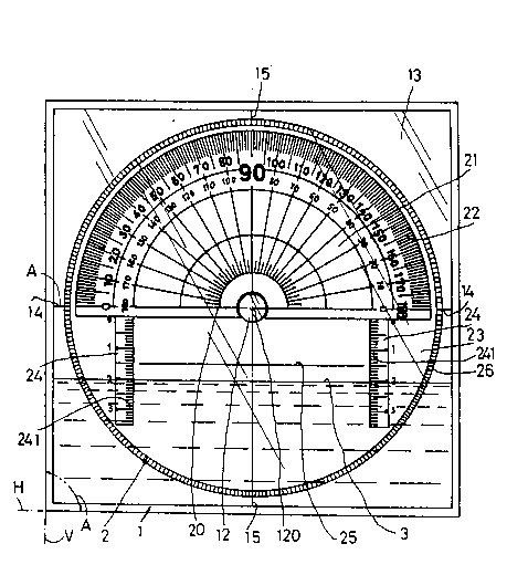
FIG. 1 is a front elevational view of the
instrument,
FIG. 2 is a cross sectional view of the
instrument,
FIG. 3 is a plane view illustrating the
measurement of a sloping surface, and
FIGS. 4 and 5 are plane views illustrating the
operations of the instrument.
As shown in FIGS. 1 and 2, the instrument includes
a casing 1, a rotating disc 2 and a coloured liquid 3
filled in the casing 1.
The casing 1 is generally square shaped and
includes a square base plate 10, a square covering


2052~62

plate 13 covering the base plate 10, an inner jacket 11
sandwiched between the base plate 10 and the covering
plate 13, a central pivot 12 formed on a central
portion of the plate 13 about a center 120 of the plate
05 13, two axial lines 14, 15 crossing each other at the
center 120 of which one axial line 14 is perpendicular
to two vertical side walls 16 and parallel to two
horizontal side walls 16, and the other axial line 15
is perpendicular to the two horizontal walls 16, but
parallel to the two vertical walls 16. All four side
walls 16 form a square of the casing 1.
The rotating disc 2 and the covering plate 13 are
made of transparent materials. A front surface lOa of
the base plate 10 is preferably made of white-color
background contrast to the coloured liquid for a clear
vision of the disc 2.
The coloured liquid 3 is filled in the inner
jacket 11 of the casing 1, and is selected from a
liquid having less cohesion to any side wall in the
jacket 11 or having low viscosity for enhancing fluid
flow for measuring easiness.
The rotating disc 2 includes: a central hole 201
pivotally engaged with the pivot 12 of the plate 13 for
rotatably mounting the disc 2 on the casing 1, an upper
half circle portion 21 and a lower half circle portion
23 divided by a central diametrical line 20 passing the
center 120, a plurality of angular graduations 22


20~2262
radially formed on a periphery of the upper half circle
portion 21 each graduation 22 corresponding to one
degree of 360 degrees of a full circle, two vertical
columns 24 parallelly formed under the diametrical line
05 20 each column 24 formed with a plurality of horizontal
graduations 241, and an annular perimeter 26 of the
disc formed as corrugated sloping surface adapted for
frictionally holding the disc 2 for its smooth
rotation.
Any two corresponding horizontal graduations 241
of the two vertical columns 24 are interpolated to form
a straight line parallel to the diametrical line 20 of
disc 2 and are to extrapolated to be perpendicular to
any vertical side wall 16. A horizontal reference line
25 is printed or formed between two central graduations
241, to be parallel to a rear liquid level of the
coloured liquid 3 filled in the casing 1. The liquid
level of the liquid 3 should be slightly positioned
under or above the reference line 25 when placing the
casing 1 on a horizontal plane. Naturally, there may be
provided with a plurality of reference lines 25 each
connected between two corresponding horizontal
graduations 241. The scale or space between every two
graduations 241 in one column 24 is not limited and not
critical. The space between every two graduations 241
may be 1 milli-meter, for instance.
When using the instrument for measuring a sloping

20~2262

angle A as shown in FIG. 3, one side wall 16 is laid on
the sloping surface S and the disc 2 is rotated about
pivot 12 to allow the reference line 25 to be parallel
to the liquid level L of the liquid 3 which level L is
05 parallel to a real horizontal plane or level H so as to
obtain an angle A such as 60 degrees by aligning the
axial line 15. Since the sloping surface S forms the
angle A with the horizontal plane H. Level L is
parallel to sloping surface 5 so that the angle A as
defined by the axial line 15 with the level L is the
true angle to be measured. The angular graduations 22
projectively matched with the axial line 15 can be
directly read from the disc, for example, 60 degrees as
shown in FIG. 3.
In FIG. 4, another sloping degree such as 30
degrees can be obtained by the method as mentioned
above. By the same way, a vertical line V (A=90
degrees) as shown in FIG. 1 can be obtained or checked
if the reference line 25 is parallel to the liquid
level while a left side wall 16 is coincided with the
left-side plane and the angular graduation matched with
the axial line 15 shows a value of 90. The reference
line 25 when parallel to the liquid level also shows a
horizontal plane H on which the casing 1 is laid as
shown in FIG. 1.
FIG. 5 shows a method to rotate the disc 2 to
allow the reference line 25 between two horizontal


2~2262

graduations 241 of the two columns 24 to be parallel to
the liquid level L in order to measure a sloping angle.
The instrument can be made as a compact unit to be
easily portable and low cost, which can be used for
05 measuring a vertical line, a horizontal line or any
sloping angles in a very convenient way.
The instrument may be in contact with a ceiling or
a beam under a roofing by aligning an upper side wall
16 with the ceiling surface or beam bottom to check
whether it is a horizontal plane, which can not be done
by a conventional bubble level.


Representative Drawing
A single figure which represents the drawing illustrating the invention.
Administrative Status

For a clearer understanding of the status of the application/patent presented on this page, the site Disclaimer , as well as the definitions for Patent , Administrative Status , Maintenance Fee  and Payment History  should be consulted.

Administrative Status

Title Date
Forecasted Issue Date 1996-10-29
(22) Filed 1991-09-25
(41) Open to Public Inspection 1992-04-02
Examination Requested 1995-09-21
(45) Issued 1996-10-29
Deemed Expired 2000-09-25

Abandonment History

There is no abandonment history.

Payment History

Fee Type Anniversary Year Due Date Amount Paid Paid Date
Application Fee $0.00 1991-09-25
Maintenance Fee - Application - New Act 2 1993-09-27 $50.00 1993-09-24
Maintenance Fee - Application - New Act 3 1994-09-26 $50.00 1994-09-26
Maintenance Fee - Application - New Act 4 1995-09-25 $50.00 1995-09-19
Maintenance Fee - Application - New Act 5 1996-09-25 $75.00 1996-08-22
Maintenance Fee - Patent - New Act 6 1997-09-25 $75.00 1997-09-04
Maintenance Fee - Patent - New Act 7 1998-09-25 $75.00 1998-07-28
Owners on Record

Note: Records showing the ownership history in alphabetical order.

Current Owners on Record
HUANG, MING-CHUNG
Past Owners on Record
None
Past Owners that do not appear in the "Owners on Record" listing will appear in other documentation within the application.
Documents

To view selected files, please enter reCAPTCHA code :


To view images, click a link in the Document Description column. To download the documents, select one or more checkboxes in the first column and then click the "Download Selected in PDF format (Zip Archive)" or the "Download Selected as Single PDF" button.

List of published and non-published patent-specific documents on the CPD .

If you have any difficulty accessing content, you can call the Client Service Centre at 1-866-997-1936 or send them an e-mail at CIPO Client Service Centre.


Document
Description 
Date
(yyyy-mm-dd) 
Number of pages   Size of Image (KB) 
Abstract 1996-10-29 1 25
Cover Page 1996-10-29 1 15
Description 1996-10-29 6 186
Claims 1996-10-29 2 69
Drawings 1996-10-29 3 81
Cover Page 1994-02-19 1 13
Abstract 1994-02-19 1 23
Claims 1994-02-19 2 66
Drawings 1994-02-19 3 78
Description 1994-02-19 6 175
Representative Drawing 1999-07-06 1 34
Prosecution Correspondence 1995-09-21 1 33
PCT Correspondence 1996-08-22 2 45
Prosecution Correspondence 1996-01-24 1 35
Office Letter 1995-11-01 1 38
Fees 1996-08-22 1 42
Fees 1995-09-19 1 39
Fees 1994-09-26 1 44
Fees 1993-09-24 1 35