Language selection

Search

Patent 2052585 Summary

Third-party information liability

Some of the information on this Web page has been provided by external sources. The Government of Canada is not responsible for the accuracy, reliability or currency of the information supplied by external sources. Users wishing to rely upon this information should consult directly with the source of the information. Content provided by external sources is not subject to official languages, privacy and accessibility requirements.

Claims and Abstract availability

Any discrepancies in the text and image of the Claims and Abstract are due to differing posting times. Text of the Claims and Abstract are posted:

  • At the time the application is open to public inspection;
  • At the time of issue of the patent (grant).
(12) Patent: (11) CA 2052585
(54) English Title: WING ATTACHMENT FOR BIRD DECOYS
(54) French Title: AILES ADAPTABLES A DES APPELANTS
Status: Expired and beyond the Period of Reversal
Bibliographic Data
(51) International Patent Classification (IPC):
  • A01M 31/06 (2006.01)
(72) Inventors :
  • BALMER, BRUCE R. (United States of America)
(73) Owners :
  • BRUCE R. BALMER
(71) Applicants :
  • BRUCE R. BALMER (United States of America)
(74) Agent:
(74) Associate agent:
(45) Issued: 2001-12-18
(22) Filed Date: 1991-10-01
(41) Open to Public Inspection: 1992-04-03
Examination requested: 1998-09-29
Availability of licence: N/A
Dedicated to the Public: N/A
(25) Language of filing: English

Patent Cooperation Treaty (PCT): No

(30) Application Priority Data:
Application No. Country/Territory Date
591,949 (United States of America) 1990-10-02

Abstracts

English Abstract


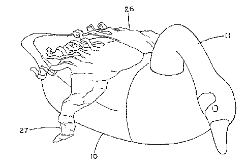
Simulated wings of light and highly flexible material
are attachable with Velcro strips to the body portion of a
bird decoy along the top center line. The material is
incapable of cantilever self-support. Preferably, an
extension arm is positioned near the leading edges of the
wing elements to make the material more accessible to air
movement. The additional function of these is simply to
hold the outer extremities of the wing elements out away
from the body portion to prevent water adhesion.


Claims

Note: Claims are shown in the official language in which they were submitted.


THE EMBODIMENTS OF THE INVENTION IN WHICH AN EXCLUSIVE
PROPERTY OR PRIVILEGE IS CLAIMED ARE DEFINED AS FOLLOWS:
1. In combination with a bird becoy, said decoy having
a body portion and a head-neck portion, a wing attachment
comprising:
at least one sheet of highly flexible material
having a wing configuration having a leading and a trailing
edge, said material having a degree of flexibility such that
it is incapable of cantilever self-support, at least a major
portion of said sheet normally drooping down about said body
portion in the absence of wind action; and
fastening means disposed along said body portion
adjacent a top center line thereof, and adapted to secure
said sheet of material thereto.
2. An attachment as defined in claim 1, wherein said
material is embossed.
3. An attachment as defined in claim 1, wherein said
sheet has a fringed trailing edge in the central portion
thereof.
4. An attachment as defined in claim 1, wherein said
body portion has a receptacle normally receiving a neck
portion, and said sheet has a portion normally engaging said
neck portion receptacle.
6

Description

Note: Descriptions are shown in the official language in which they were submitted.


WING ATTACHMENT FOR BIRD DECOYS
BACKGROUND OF THE INVENTION
Hunters of ducks and geese often use decoys to bring
the birds within shooting range. It seems generally agreed
that the more life-like 'the decays are, the better. Some
form of motion, such as body movement or wing-flapping, also
appears to make the decoys more effective. Decoys with
movable wings have been manually operated (by pull lines),
motorized, or simply moved by wind action. Decoys
simulating predatory birds can be used to repel birds
normally preyed upon, and decoy motion is also effective in
such cases.
Moving wing attachments to otherwise standard decoys
have been of various designs. These range from wings taken
from live birds (and secured to the decoys with rubber
bands) to wings of flexible sheet material secured to the
backs of the decoys along the center line. These have been
used with both full-body and silhouette decoys.
Occasionally, non-game birds are simulated by decoys to lend
realism to the scene where the added birds are frequently
seen in the company of the game birds.
SUMMARY OF THE INVENTION
Wing elements of a highly flexible material are secured
to the back of the body of a bird decoy along the top center
line. The material is incapable of cantilever self-support,
and is light and also waterproof to prevent the absorption
of water, and the consequent increase in weight. These wing
elements are thus able to move under the influence of very
little wind. The preferred form includes extension arms

CA 02052585 2000-11-29
near the leading edges of the wings to hold the wing
material out away from th.e body of the decoy to give the
wind a better access to it. This arrangement also tends to
prevent the wing material from being stuck to the body by
the presence of water. Th.e wing elements are made attachable
to the standard decoys by the 'use of Velcro strips.
According to the present invention there is provided
in combination with a bird becoy, said decoy having a body
portion and a head-neck portion, a wing attachment
comprising:
at least one sheet of highly flexible material
having a wing configuration having a leading and a trailing
edge, said material having a degree of flexibility such that
it is incapable of cantilever self-support, at least a major
portion of said sheet normally drooping down about said body
portion in the absence of: wind action; and
fastening means disposed along said body portion
adjacent a top center line thereof, and adapted to secure
said sheet of material thereto.
DESCRIPTION OF THE DRAWINGS
FIG. 1 is a perspective view of a standard full-body
decoy, with a pair of separable wing elements secured along
the back center line. Both of the wing elements have
extension arms adjacent t=he leading edge.
FIG. 2 is a perspective view of a full-body decoy
showing a pair of wing elements without extension arms.
FIG. 3 is an exploded view showing the relative position
in cross-section of the body portion of the decoy and the
wing elements.
FIG. 4 is a view of i~he underside of a one-piece wing
element extending over the full span.
FIG. 5 is a perspective view of a full-body decoy with a
removable neck-head section, and showing a wing element with
2

CA 02052585 2000-11-29
a tab that can be tucked into the opening receiving the
lower extremity of the neck far securing the wing element in
position.
FIG. 6 is a fragment<~ry section of a recommended type of
material for the wing el~=menu, showing the embossed
pattern.
'La

~~:~~;~~'a
DESCRIPTION OF THE PREFERRED EMBODIMENTS
Referring to FTG. l, the illustrated full-body decoy
has a body portion 10 with a head-neck portion 11 that is
removable as shown in FIG. 5. 'This is relatively standard
construction. A form of twist lock is usually employed to
secure these -two components together. The wing elements 12
and 13 are secured to the back at the top center line, and
meet along the line 14. Each of the wing elements has a
leading edge as shown at 15 and 16, and a trailing edge 17-
18. Approximately the inner third of the trailing edge is
shredded as shown at 19 and 20 to provide strips that float
easily with the slightest breeze, and produce the appearance
of a bird fluffing up its feathers.
The preferred material for the wing elements is a thin
plastic sheet of a type which does not absorb significant
amounts of water. Polypropylene or polyethylene have been
found suitable in thicknesses ranging from three to fifteen
mils. It has been found that the use of embossed material
not only produces an apparent texture similar to the
feathers of a bird, but also tends to prevent the adhesion
of the wing elements to the body portion of the bird in -the
presence of water. A material developed for a completely
different purpose has been found surprisingly effective.
This material has been developed for agricultural purposes,
and is sometimes referred to as "weed-barrier film". The
preferred coloring of this material will be determined
largely by the type of decoy being used, which will have its
characteristic coloring on the body portion.
FIG. 1 illustrates a form of the invention in which the
wing elements are stiffened along the leading edge by 'the
3

presence of extension rods 21 and 22, primarily to hold 'the
wing elements out away from 'the body portion so that the
wind can have a better access to it. The securing of -the
wing elements along the center a_ine of the body portion
permits the rods to bear along the sides of -the body
portion, as they are held down in the center. The preferred
central attachment is through the use of mating Velcro
strips 23 and 24, as shown in FIG. 3. In FIG. 3, the single
wing element 25 is not provided with the extension rods, and
is merely left to drape around the body portion 10 in a
random fashion, as shown in FIG. 2. In FIG. 2, the loosely-
drooping wing elements 26 and 27 are separable; but since
they can be folded, they can as well be made in one piece,
as shown in FIG. 3. The fringed trailing edges are
preferably incorporated in all forms of the wing elements.
In FIG. 4, the one-piece full-span wing element 28 is shown
with the extension rods 29 and 30, and these may be
discontinuous in the central portion adjacent the Velcro
strip 31 to enable the entire unit to be folded along the
center line. The shredded trailing edge portions 32 and 33
are as previously described.
Referring to FIG. 5, the head-neck section 11 of the
decoy is shown provided with the section 34 adapted to enter
the receptacle opening 35 in the body portion, and to be
retained in assembled position by the twist lock 36 of
standard design. The one piece wing element 37 (without
extension rods) is provided with a short flap 38 adapted to
be tucked into the opening 35 prior to the interengagement
of the head-neck unit, as a means of retaining the wing
element 37 in place. This may be supplemented by the
additional use of the Velcro strips along the back center
4

line. FIG. 6 illustrates a recommended embossing pattern
for the sheet material of the wing elements.

Representative Drawing
A single figure which represents the drawing illustrating the invention.
Administrative Status

2024-08-01:As part of the Next Generation Patents (NGP) transition, the Canadian Patents Database (CPD) now contains a more detailed Event History, which replicates the Event Log of our new back-office solution.

Please note that "Inactive:" events refers to events no longer in use in our new back-office solution.

For a clearer understanding of the status of the application/patent presented on this page, the site Disclaimer , as well as the definitions for Patent , Event History , Maintenance Fee  and Payment History  should be consulted.

Event History

Description Date
Inactive: Office letter - MF 2011-02-09
Inactive: Office letter - MF 2010-11-09
Inactive: Office letter 2010-11-09
Revocation of Agent Requirements Determined Compliant 2010-11-09
Time Limit for Reversal Expired 2010-10-01
Revocation of Agent Request 2010-09-17
Letter Sent 2009-10-01
Extension of Time to Top-up Small Entity Fees Requirements Determined Compliant 2008-09-19
Inactive: Late MF processed 2008-09-05
Letter Sent 2007-10-01
Grant by Issuance 2001-12-18
Inactive: Cover page published 2001-12-17
Inactive: Final fee received 2001-07-31
Pre-grant 2001-07-31
Letter Sent 2001-01-31
Notice of Allowance is Issued 2001-01-31
Inactive: Approved for allowance (AFA) 2001-01-17
Amendment Received - Voluntary Amendment 2000-11-29
Inactive: S.30(2) Rules - Examiner requisition 2000-05-31
Letter Sent 1998-10-16
Inactive: Application prosecuted on TS as of Log entry date 1998-10-15
Amendment Received - Voluntary Amendment 1998-10-15
Inactive: Status info is complete as of Log entry date 1998-10-15
Request for Examination Requirements Determined Compliant 1998-09-29
All Requirements for Examination Determined Compliant 1998-09-29
Application Published (Open to Public Inspection) 1992-04-03
Small Entity Declaration Determined Compliant 1991-10-01

Abandonment History

There is no abandonment history.

Maintenance Fee

The last payment was received on 2001-10-01

Note : If the full payment has not been received on or before the date indicated, a further fee may be required which may be one of the following

  • the reinstatement fee;
  • the late payment fee; or
  • additional fee to reverse deemed expiry.

Patent fees are adjusted on the 1st of January every year. The amounts above are the current amounts if received by December 31 of the current year.
Please refer to the CIPO Patent Fees web page to see all current fee amounts.

Fee History

Fee Type Anniversary Year Due Date Paid Date
MF (application, 6th anniv.) - small 06 1997-10-01 1997-09-09
MF (application, 7th anniv.) - small 07 1998-10-01 1998-09-29
Request for examination - small 1998-09-29
MF (application, 8th anniv.) - small 08 1999-10-01 1999-08-06
MF (application, 9th anniv.) - small 09 2000-10-02 2000-09-25
Final fee - small 2001-07-31
MF (application, 10th anniv.) - small 10 2001-10-01 2001-10-01
MF (patent, 11th anniv.) - small 2002-10-01 2002-09-27
MF (patent, 12th anniv.) - small 2003-10-01 2003-09-12
MF (patent, 13th anniv.) - small 2004-10-01 2004-08-23
MF (patent, 14th anniv.) - small 2005-10-03 2005-09-30
MF (patent, 15th anniv.) - small 2006-10-02 2006-08-02
MF (patent, 16th anniv.) - standard 2007-10-01 2008-09-05
MF (patent, 17th anniv.) - standard 2008-10-01 2008-09-05
Reversal of deemed expiry 2007-10-01 2008-09-05
Owners on Record

Note: Records showing the ownership history in alphabetical order.

Current Owners on Record
BRUCE R. BALMER
Past Owners on Record
None
Past Owners that do not appear in the "Owners on Record" listing will appear in other documentation within the application.
Documents

To view selected files, please enter reCAPTCHA code :


To view images, click a link in the Document Description column (Temporarily unavailable). To download the documents, select one or more checkboxes in the first column and then click the "Download Selected in PDF format (Zip Archive)" or the "Download Selected as Single PDF" button.

List of published and non-published patent-specific documents on the CPD .

If you have any difficulty accessing content, you can call the Client Service Centre at 1-866-997-1936 or send them an e-mail at CIPO Client Service Centre.

({010=All Documents, 020=As Filed, 030=As Open to Public Inspection, 040=At Issuance, 050=Examination, 060=Incoming Correspondence, 070=Miscellaneous, 080=Outgoing Correspondence, 090=Payment})


Document
Description 
Date
(yyyy-mm-dd) 
Number of pages   Size of Image (KB) 
Description 1994-02-04 5 146
Drawings 1994-02-04 3 61
Claims 1994-02-04 1 25
Abstract 1994-02-04 1 13
Description 2000-11-28 6 171
Claims 2000-11-28 1 30
Representative drawing 2001-11-19 1 10
Representative drawing 1999-04-21 1 14
Reminder - Request for Examination 1998-06-01 1 117
Acknowledgement of Request for Examination 1998-10-15 1 177
Commissioner's Notice - Application Found Allowable 2001-01-30 1 164
Maintenance Fee Notice 2007-11-12 1 171
Late Payment Acknowledgement 2008-09-18 1 164
Maintenance Fee Notice 2009-11-11 1 170
Correspondence 2001-07-30 1 29
Correspondence 2010-09-16 1 19
Correspondence 2010-11-08 1 14
Correspondence 2010-11-08 1 25
Fees 1994-09-29 1 51
Fees 1996-09-26 1 49
Fees 1995-09-28 1 55
Fees 1993-09-30 2 57