Language selection

Search

Patent 2052667 Summary

Third-party information liability

Some of the information on this Web page has been provided by external sources. The Government of Canada is not responsible for the accuracy, reliability or currency of the information supplied by external sources. Users wishing to rely upon this information should consult directly with the source of the information. Content provided by external sources is not subject to official languages, privacy and accessibility requirements.

Claims and Abstract availability

Any discrepancies in the text and image of the Claims and Abstract are due to differing posting times. Text of the Claims and Abstract are posted:

  • At the time the application is open to public inspection;
  • At the time of issue of the patent (grant).
(12) Patent: (11) CA 2052667
(54) English Title: MASONRY SCREW ANCHOR
(54) French Title: ANCRE DE MACONNERIE A VIS
Status: Expired and beyond the Period of Reversal
Bibliographic Data
(51) International Patent Classification (IPC):
  • E04C 5/12 (2006.01)
  • F16B 13/02 (2006.01)
  • F16B 25/00 (2006.01)
(72) Inventors :
  • DIXON, TONY L. (United States of America)
  • STARKE, DAVID E. (United States of America)
  • PIACENTI, FRANK (United States of America)
  • BROWN, ROBERT W. (United States of America)
(73) Owners :
  • EMHART INC.,
(71) Applicants :
  • EMHART INC., (United States of America)
(74) Agent: NORTON ROSE FULBRIGHT CANADA LLP/S.E.N.C.R.L., S.R.L.
(74) Associate agent:
(45) Issued: 1995-01-17
(22) Filed Date: 1991-10-02
(41) Open to Public Inspection: 1992-04-04
Examination requested: 1992-03-17
Availability of licence: N/A
Dedicated to the Public: N/A
(25) Language of filing: English

Patent Cooperation Treaty (PCT): No

(30) Application Priority Data:
Application No. Country/Territory Date
592,138 (United States of America) 1990-10-03

Abstracts

English Abstract


A masonry screw anchor having two
different constant diameter shank portions
connected via a taper. Each portion has a set of
constant diameter threads and intermediate smaller
diameter protrusions with the threads and
protrusions on the larger diameter shank portion
being larger in diameter than the diameter of the
threads and protrusions on the smaller diameter
portion.


Claims

Note: Claims are shown in the official language in which they were submitted.

The embodiments of the invention in which an exclusive
property or privilege is claimed are defined as follows:
1. A masonry screw anchor comprising:
an elongated shank portion including a lower portion having
a pointed end and an adjacent upper portion joined
therewith,
a first set of constant diameter threads on said lower
shank portion,
a first set of constant diameter helical protrusions, having
a diameter smaller than the diameter of said first set
of threads, on said lower shank portion between said
threads, and
a second set of constant diameter threads on said upper
shank portion, said second set of threads having a
larger diameter than the diameter of said first set of
threads.

2. A masonry screw anchor comprising:
a head portion,
an elongated shank including a lower shank portion having
a pointed end and an upper shank portion intermediate
said head portion and said lower shank portion and
joined therewith,
a first set of threads on said lower shank portion having a
first constant diameter,
a first set of constant diameter helical protrusions, having
a diameter smaller than said first constant diameter,
and positioned on said lower shank portion between said
first set of threads,
a second set of threads on said upper shank portion having a
second constant diameter, said second constant diameter
being larger than said first constant diameter.

3. A masonry screw anchor comprising:
an elongated shank portion including a smaller constant
diameter portion having a pointed end and an adjacent
larger diameter portion joined therewith via a tapered
portion,
a first set of constant diameter threads on said smaller
diameter shank portion,
a first set of constant diameter helical protrusions, having
a diameter smaller than the diameter of said first set
of threads, on said smaller diameter shank portion
between said threads, and
a second set of constant diameter threads on said larger
diameter shank portion, said second set of threads
having a larger diameter than the diameter of said
first set of threads,

4. A masonry screw anchor according to claim 3
wherein there is further provided a second set of
constant diameter helical protrusions, having a
diameter smaller than the diameter of said second set
of threads, on said larger diameter shank portion
between said second threads.
5. A masonry screw anchor according to claim 4
wherein the ratio of thread diameter to protrusion
diameter for the large shank portion is equal to the
same ratio for the smaller shank portion.

Description

Note: Descriptions are shown in the official language in which they were submitted.


2052667
SPECIFICATION
MASONRY SCREW ANCHOR
The present invention relates generally
to an anchor device which is designed to be
secured within a bore formed in a masonry
structure.
Another object of this invention is to
provide a screw which has high torsional
resistance to minimize breakage that can occur
during installation.
A state of the art anchor device is
disclosed in U.S. Patent No. 4,657,460. That
anchor is formed with a sharp helical thread which
has a tapering crest diameter which decreases from
the trailing extremity of the shank to the
entering extremity. Notches formed on the crests
of the helical thread provide a means for allowing
the helical thread to become firmly embedded in
the side walls of the bore hole. A series of
helical protrusions are spaced along the shank
which provide a means of guiding the screw.
One of the problems with this type
anchor design is that the tapered thread acts like
a wedge. The deeper it is driven the higher the
drive torque to install and this can lead to
premature breakage of the screw during
installation.
Another negative of this design, which
is formed by roll forming dies, is that since the
threads are tapered special roll forming dies must
be used.
It is accordingly an object of the
present invention to provide an effective masonry
screw which can be manufactured using commercially
available roll form dies to form the threads.
.~
I

'~ - 2 - 2052667
This will allow for more control of tolerances
pertaining to thread diameter and would also contribute
to longer die life.
It is the object of the present invention to
provide a masonry anchor which will require a low
driving torque but will still provide good resistance
to pullout and shear.
According to the above objects, from a broad
aspect, the present invention provides a masonry screw
anchor which comprises an elongated shank portion
including a lower portion having a pointed end and an
adjacent upper portion joined therewith. A first set
of constant diameter threads are provided on the lower
shank portion. A first set of constant diameter
helical protrusions are provided on the lower shank
portion between the threads, and have a diameter
smaller than the diameter of the first set of threads.
A second set of constant diameter threads are provided
on the upper shank portion. This second set of threads
has a larger diameter than the diameter of the first
set of threads.
Other objects and advantages of the present
invention will become apparent from the following
portion of the specification and drawings which
indicate in accordance with the mandate of the patent
which statutes a presently preferred embodiment
incorporating the principles of the invention.
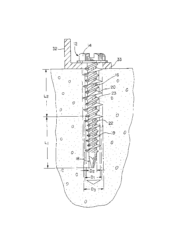
Referring to the drawings:
Figure 1 is a side elevational view of an anchor
device made in accordance with the teachings of the
present invention embedded in a masonry-like structure;
and
Figure 2 is an enlarged partial elevation view
of a portion of the anchor device shown in Fig. 1.
The masonry screw (10) as illustrated in Fig. 1
is shown with a large head section (12) with
appropriate rotation inducing surfaces (14) and an
.,

`~ - 2a - 20~2667
elongated shank (16) with a substantially pointed
entering extremity (18). A first set of constant
diameter Dl, somewhat flat crested helical threads (19)
are formed along the constant diameter D2 length Ll of
the shank providing a first set of helical protrusions.
A second set of constant diameter D3 sharp crested
helical threads (20) having a larger diameter than the
crest diameter Dl of the first set of threads 19 is

_ 3 _ 2 052 6 67
formed on the upper length L2 of the shank which
has a uniform diameter D2 which is greater than
the diameter D2 of the lower shank portion.
Spaced between the adjacent protrusions of the
first set of threads 19 is a set of helical
protrusions (22). The threads (19) and the
helical protrusions (22) will have approximately
the same pitch and the crest diameter Dl, D2 of
the thread (19) will be greater than the radial
dimension of the helical protrusion (22).
Similarly spaced between the adjacent protrusions
of the second set of threads 20 is a set of
helical protrusions (23) which will have the same
pitch as the second set of threads and will have a
diameter D6 slightly smaller than the crest
diameter D3 of the second set of threads.
The crest diameter of the screw anchor
is tapered or stepped 30 as indicated in Fig. 2 to
merge the smaller diameter shank portion D2 with
the larger diameter portion D4 and the ratio of
large crest diameter D3 to large helical
protrusions diameter D6 is the same as the ratio
of small crest diameter Dl to small helical
protrusions diameter D5.
The masonry like structure (28) is
provided with a bore (30) through the use of a
conventional masonry drilling device. One of the
advantages of the present invention is that the
fixture to be attached (32) may be positioned on
the support structure and provided with an
aperture (33) during the drilling operation. When
the fixture and structure has been prepared the
anchor device (10) is inserted in the bore (30)
utilizing fastener drilling apparatus.
As the anchor device (10) is rotated and

-
~ 4 ~ 2 052 ~ 67
axially inserted into the bore, the relatively
flat crests of the lead thread (19) form threads
into the concrete and are embedded into the side
walls of the bore. As the device is driven deeper
the upper threaded portion (20) having the sharp
crested larger diameter threads further engages
the threads in the concrete formed by the lower
threads (19). The included angle of the threads
(19) and (20) are approximately 30 degrees to
facilitate the embedment. The radial protrusions
(22), (23) which are of a smaller diameter than
the bore aid in centering and guiding the device
into the bore without adding additional torsional
stress during initial installation.

Representative Drawing
A single figure which represents the drawing illustrating the invention.
Administrative Status

2024-08-01:As part of the Next Generation Patents (NGP) transition, the Canadian Patents Database (CPD) now contains a more detailed Event History, which replicates the Event Log of our new back-office solution.

Please note that "Inactive:" events refers to events no longer in use in our new back-office solution.

For a clearer understanding of the status of the application/patent presented on this page, the site Disclaimer , as well as the definitions for Patent , Event History , Maintenance Fee  and Payment History  should be consulted.

Event History

Description Date
Inactive: IPC from MCD 2006-03-11
Time Limit for Reversal Expired 2002-10-02
Letter Sent 2001-10-02
Grant by Issuance 1995-01-17
Application Published (Open to Public Inspection) 1992-04-04
All Requirements for Examination Determined Compliant 1992-03-17
Request for Examination Requirements Determined Compliant 1992-03-17

Abandonment History

There is no abandonment history.

Fee History

Fee Type Anniversary Year Due Date Paid Date
MF (patent, 6th anniv.) - standard 1997-10-02 1997-09-10
MF (patent, 7th anniv.) - standard 1998-10-02 1998-09-10
MF (patent, 8th anniv.) - standard 1999-10-04 1999-09-20
MF (patent, 9th anniv.) - standard 2000-10-02 2000-09-21
Owners on Record

Note: Records showing the ownership history in alphabetical order.

Current Owners on Record
EMHART INC.,
Past Owners on Record
DAVID E. STARKE
FRANK PIACENTI
ROBERT W. BROWN
TONY L. DIXON
Past Owners that do not appear in the "Owners on Record" listing will appear in other documentation within the application.
Documents

To view selected files, please enter reCAPTCHA code :


To view images, click a link in the Document Description column. To download the documents, select one or more checkboxes in the first column and then click the "Download Selected in PDF format (Zip Archive)" or the "Download Selected as Single PDF" button.

List of published and non-published patent-specific documents on the CPD .

If you have any difficulty accessing content, you can call the Client Service Centre at 1-866-997-1936 or send them an e-mail at CIPO Client Service Centre.


Document
Description 
Date
(yyyy-mm-dd) 
Number of pages   Size of Image (KB) 
Cover Page 1995-01-17 1 17
Abstract 1995-01-17 1 13
Description 1995-01-17 5 157
Claims 1995-01-17 4 73
Drawings 1995-01-17 2 49
Representative drawing 1999-07-06 1 22
Maintenance Fee Notice 2001-10-30 1 178
Fees 1996-09-16 1 39
Fees 1995-09-14 1 42
Fees 1994-09-30 1 66
Fees 1993-09-21 1 42
PCT Correspondence 1994-10-19 1 45
Courtesy - Office Letter 1992-05-25 1 29
Prosecution correspondence 1992-02-24 1 32
Prosecution correspondence 1992-03-17 1 38
Prosecution correspondence 1993-07-12 2 48