Language selection

Search

Patent 2052684 Summary

Third-party information liability

Some of the information on this Web page has been provided by external sources. The Government of Canada is not responsible for the accuracy, reliability or currency of the information supplied by external sources. Users wishing to rely upon this information should consult directly with the source of the information. Content provided by external sources is not subject to official languages, privacy and accessibility requirements.

Claims and Abstract availability

Any discrepancies in the text and image of the Claims and Abstract are due to differing posting times. Text of the Claims and Abstract are posted:

  • At the time the application is open to public inspection;
  • At the time of issue of the patent (grant).
(12) Patent Application: (11) CA 2052684
(54) English Title: A.C. ELECTRICAL POWER SUPPLY INSTALLATION COMPRISING A BACK-UP POWER SUPPLY EQUIPPED WITH AN INVERTER OPERATING IN REVERSIBLE MODE
(54) French Title: CIRCUIT D'ALIMENTATION CA COMPRENANT UNE ALIMENTATION DE SECOURS AVEC CONVERTISSEUR FONCTIONNANT EN MODE REVERSIBLE
Status: Deemed Abandoned and Beyond the Period of Reinstatement - Pending Response to Notice of Disregarded Communication
Bibliographic Data
(51) International Patent Classification (IPC):
  • H2M 5/45 (2006.01)
  • H2J 3/16 (2006.01)
  • H2J 9/06 (2006.01)
(72) Inventors :
  • FIORINA, JEAN-NOEL (France)
  • TENAUD, PATRICK (France)
(73) Owners :
  • MERLIN GERIN
(71) Applicants :
  • MERLIN GERIN (France)
(74) Agent: ROBIC AGENCE PI S.E.C./ROBIC IP AGENCY LP
(74) Associate agent:
(45) Issued:
(22) Filed Date: 1991-10-03
(41) Open to Public Inspection: 1992-04-09
Examination requested: 1998-10-02
Availability of licence: N/A
Dedicated to the Public: N/A
(25) Language of filing: English

Patent Cooperation Treaty (PCT): No

(30) Application Priority Data:
Application No. Country/Territory Date
9012475 (France) 1990-10-08

Abstracts

English Abstract


ABSTRACT
A.C. ELECTRICAL POWER SUPPLY INSTALLATION COMPRISING A BACK-UP
POWER SUPPLY EQUIPPED WITH AN INVERTER OPERATING IN REVERSIBLE
MODE
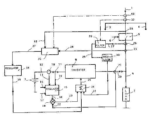
A first control loop (10, 11, 13 to 19, 21 to 25) enables the
inverter (8) to be made to operate as a current generator when
it recharges the back-up power supply battery (7), Two other
control loops (28 to 31, 33 to 39) enable the inverter (8) to
compensate on the one hand the harmonics, and on the other hand
the reactive part of the current absorbed by the load, when the
inverter is on stand-by.
Refer to the single figure.


Claims

Note: Claims are shown in the official language in which they were submitted.

CLAIMS
1. An installation to supply AC electrical power to a load (2)
from a mains power supply (1), this installation comprising an
auxiliary back-up power supply equipped with a bank of
rechargeable batteries (7) and a reversible inverter (8), with
means for recharging this battery (7), by the mains power supply
(1, 9) and via this reversible inverter (8), when this mains
power supply supplies the load (2) normally, characterized in
that it is equipped with means (10, 11, 13 to 19, 21 to 25) for
the inverter (8) to take from this mains power supply, when the
mains power supply is operating normally and is supplying the
load, an active current whose amplitude is proportional to the
direct current then necessary to charge this battery (7), so
that the inverter operates as a current generator when, being on
stand-by, it is used to recharge the battery.
2. The installation according to claim 1, characterized in that
said means comprise means (10) for measuring the direct current
supplied by the inverter (8) to the battery (7), means (11) for
measuring the DC voltage at the battery terminals, a first
electronic regulator (15) comprising inputs (13, 14) connected
respectively to the means (10, 11) for measuring the DC current
and DC voltage of the battery, and inputs (16, 17) to which
battery charging current and voltage reference values are
applied, the output of the first regulator (15) being applied to
a first input (18) of a comparator (19) a second input (22) of
which is connected to means (21) for measuring the current
supplied to the inverter (8) by the mains power supply, the
output (23) of the comparator (19) being connected to a control
input (25) of the inverter (8).
3. The installation according to claim 1, characterized in that
it is in addition equipped with means for compensating harmonics
(28 to 31, 24, 25) designed, when the inverter is on stand-by,

to cancel out the harmonics of the current supplied to the load
by the mains power supply (1), the inverter (8) supplying the
load with the harmonics it absorbs.
4. The installation according to claim 3, characterized in that
the means for compensating harmonics comprise a high-pass filter
(28) whose input is connected to means (26, 32) for measuring
the current supplied to the load (2) by the mains power supply
(1), and a second electronic regulator (30) whose input is
connected to the output of the high-pass filter and whose output
is connected to a control input (25) of the inverter (8).
5. The installation according to claim 4, characterized in that
the means for measuring the current supplied to the load
comprise a sensor (32) which is placed sufficiently upline on
the mains power supply (1) for the inverter (8) to also
eliminate the current harmonics of the mains power supply (1)
which are due to other users.
6. The installation according to claim 1, characterized in that
it is in addition equipped with means for compensating the
reactive part (33 to 39, 24, 25) designed, when the inverter is
on stand-by, to cancel out the reactive part of the current
supplied to the load by the mains power supply (1), the inverter
(8) supplying the load with the reactive part of the current it
absorbs.
7. The installation according to claim 6, characterized in that
the means for compensating the reactive part comprise a device
(35) for extracting the reactive part connected to second means
(33, 40) for measuring the current supplied to the load (2) by
the mains power supply (1), and means (36) for measuring the
voltage of the mains power supply (1), the output of the
extraction device (35) being connected to a third electronic
regulator (38) whose output is connected to a control input (25)

of the inverter (8).
8. The installation according to claim 7, characterized in that
the second means for measuring the current comprise a sensor
(40) which is placed sufficiently upline on the mains power
supply (1) for the inverter (8) to operate as a cos ?
compensator.

Description

Note: Descriptions are shown in the official language in which they were submitted.


A.C. ELECTRICAL POWER SUPPLY INSTALLATION COMPRISING A BACK-UP
POh~R SUPPLY EQUIPPED WITH AN INVERTER OPERATING IN REVERSIBLE
MODE
BACKGROUND OF THE INVENTION
The present invention relates to an AC electrical power supply
installation, comprising a back-up power supply equipped with an
inverter operating in reversible mode.
It is state of the art to equip the installation supplying power
to a load with a back-up power supply capable of provisionally
replacing the main power supply, whether it be single or multi-
phase, in the event of failure of the latter. This back-up power
supply uses the power supplied by a bank of batteries. This
battery bank supplies a reversible inverter which operates, in
both directions, as a voltage generator. In the event of a mains
power supply failure, the load is automatically disconnected by
a static contactor provided for this purpose, and it is then the
back-up power supply which supplies, via its inverter, the AC
electrical power to this load. The inverter being energized in
reversible mode, it is via the latter that the battery is
recharged by the mains power supply when, everything having
reverted to normal, it is again supplying the load.
In installations of this kind, a dephasing inductance is
generally connected between the above-mentioned static contactor
and the load, in order to obtain an inverter current and voltage
in phase, when the batteries are recharged via the reversible
inverter (U.S. Patent 4,673,825, U.S. Patent 4,238,691). This
solution has the drawbac~s of both increasing the cost price of
the installation, and of causing a relatively high current to
flow in the inverter when, being on stand-by, its only function
is to act as the battery recharging circuit.

2 ~ .~, ',
SUMMARY OF THE INVENTION
_
The object of the invention is to overcome these drawbacks. It
relates for this purpose to an installation to supply AC
electrical power to a load from the mains power supply, this
installation comprising an auxiliary back-up power supply
equipped with a bank of rechargeable batteries and a reversible
inverter, with means for recharging this battery, by the mains
power supply and via this reversible inverter, when this mains
power supply supplies the load normally, and this installation
being characterized by the fact that it is equipped with means
for the inverter to take from this mains power supply! when the
mains power supply is operating normally and is supplying the
load, an active current whose amplitude is proportional to the
direct current then necessary to recharge this battery, so that
the inverter operates as a current generator when, being on
stand-by, it is used to perform this recharging.
This installation can moreover be advantageously equipped with
means for compensating harmonics designed, when the inverter is
on stand-by, to cancel out the harmonics of the current supplied
to the load by the mains power supply, the inverter supplying
the load with the harmonics it absorbs.
The same installation can also advantageously be equipped with
means for compensating the reactive part designed, when the
inverter is on stand-by, to cancel out the reactive part of the
current supplied to the load by the mains power supply, the
inverter supplying the load with the reactive part of the
current it absorbs.
BRIEF DESCRIPTION OF THE DRAWING
Anyway, the invention will be easily understood, and its
advantages and other features will become more clearly apparent

2 0 ~
from the following description of an illustrative embodiment of
the invention, given as a non-restrictive example only,
referring to the accompanying drawing whose single figure
represents a block diagram of this installation, in single-phase
current in this example.
DESCRIPTION OF THE PREFERRED EMBODIMENT
Referring to this single figure, reference 1 designates the
input of the AC mains supply, assumed here to be single-phase
essentially to simplify the drawing, supplying electrical power
to a load 2, and other users 3 and 4.
Between the single-phase mains 1 and this load 2 there is
located a static contactor 5 controled at 6 by signals from a
central measuring, computing and control device tnot
represented), in order to disconnect the load 2 from the mains
supply 1 in the event of failure of the latter. In this case,
the static contactor 5 is kept open by the signal at 6, and the
load 2 is then provisionally supplied by a back-up power supply
comprising a bank of batteries 7 and a reversible inverter 8.
When the mains system 1 operates normally, the static contactor
5 is kept closed, and the mains system 1 not only supplies the
load 2 via the line 9, but also recharges the bank of batteries
7, via the reversible inverter 8 whose chopping strategy is
suitably adjusted.
According to a first feature of the invention, this inverter 8,
which in the event of a failure of the mains supply 1 operates
as a voltage generator supplying the load 2, is made to operate
as a current generator when, the mains 1 being present normally
and supplying the load, it is used to recharge the battery 7.
This result is obtained by making the inverter 8 take, from the
line 9 connecting the mains supply to the load, i.e. in fact

j3 (t 11
from the mains supply 1, an active current whose amplitude is
proportional to the DC current then necessary to recharge this
battery 7.
For this purpose, a DC current sensor 10 and a DC voltage
measuring point 11 are provided on the input/output wire 12 of
the battery 7, and this charging current and voltage data is
applied respectively at 13 and 14 to an electronic regulator 15,
which in addition receives at 16 and 17 the battery charging
current and voltage references generated by the above-mentioned
central control device.
This regulator 15 consequently provides, on a first input 18 of
a comparator 19, an input AC current setpoint of the inverter 8,
which is compared with a real input current taken from the
input/output conductor 20 of the inverter by a current
transformer 21 and applied to the second input 22 of this
comparator 19.
The output 23 of this comparator 19 is applied, via a summer 24
whose role will become apparent hereafter, to a control input 25
of the inverter 8, in order to modify its chopping strategy
accordingly.
According to another feature of the invention, this same
chopping strategy is furthermore modified so that the inverter
inputs, via the conductor 20, to the line 9, a current such that
the mains only has to supply the fundamental component of the AC
current absorbed by the load, the inverter supplying the current
harmonics absorbed by the load.
For this purpose, the mains current is taken off at 26, downline
from the static contactor 5, by a current transformer, and is
applied at 27 to a high-pass filter 28 capable of rejecting the
fundamental component of this current and of letting all its

2~2~
s
harmonics pass. The output 29 of this filter is applied to an
electronic regulator 30 whose transfer function is determined to
apply, via its output 31, the summer 24, and abov~-mentioned
input 25, modification signals to the inverter 8 of its chopping
strategy tending to cancel out the harmonics of the mains
current taken at 26. The inverter supplies the harmonics it
absorbs to the load 2, via the conductor 2~ and line 9, the
mains 1 supplying only the fundamental component of the current.
Control of the inverter is thus included in a lock-loop designed
to cancel out the harmonics of the current in the mains power
supply 1.
As an alternative embodiment, the current sensor can be placed
at 32, upline from the static contactor 5, and the device then
serves the purpose of depolluting the mains power supply 1, for
it then also eliminates the current harmonics of the mains power
supply which are due to other users.
According to yet another feature of the invention, this chopping
strategy is also modified so that the inverter 8 inputs to the
line 9, via the conductor 20, a current such that the mains
power supply 1 only has to supply the active part of the current
absorbed by the load, the inverter supplying the reactive part
of the current absorbed by the load. The mains power supply then
sees the load 2 as "cos. ~ = 1".
To this end, the mains power supply current is taken downline
from the static contactor 5 by a current transformer 33, and is
applied at 34 to a device 35 for extracting the dephased
current/voltage part (i.e. the reactive part of the current),
which receives on its other input 41 data representative of the
corresponding voltage, taken at 36 on the line 1. The output 37
of this extraction device is applied to an electronic regulator
38 whose transfer function is determined to apply, via its
output 39, the summer 24, and again the input 25, modification

2 iJ ~
signals to the inverter 8 of its chopping strategy tending to
cancel out the reactive part of the mains supply current taken
at 33. The inverter supplies to the load 2, via the conductor 20
and line 9, the reactive part of the current it absorbs. Control
of the inverter is thus included in a lock-loop designed to
cancel out the reactive part of the current in the mains supply
1.
As an alternative embodiment, this current sensor can be placed
at 40, upline from the static contactor 5, so that the inverter
8 also acts as a cos. ~ compensator, for it also compensates
the reactive part of the current due to other users.
The invention is naturally in no way limited to the embodiment
particularly described above, and can be applied for example
equally well to a multiphase power supply. In a more general
manner, it also covers other equivalent embodiments, whether
they be more sophisticated or less so.

Representative Drawing
A single figure which represents the drawing illustrating the invention.
Administrative Status

2024-08-01:As part of the Next Generation Patents (NGP) transition, the Canadian Patents Database (CPD) now contains a more detailed Event History, which replicates the Event Log of our new back-office solution.

Please note that "Inactive:" events refers to events no longer in use in our new back-office solution.

For a clearer understanding of the status of the application/patent presented on this page, the site Disclaimer , as well as the definitions for Patent , Event History , Maintenance Fee  and Payment History  should be consulted.

Event History

Description Date
Inactive: IPC from MCD 2006-03-11
Application Not Reinstated by Deadline 2003-02-21
Inactive: Dead - Final fee not paid 2003-02-21
Deemed Abandoned - Failure to Respond to Maintenance Fee Notice 2002-10-03
Deemed Abandoned - Conditions for Grant Determined Not Compliant 2002-02-21
Notice of Allowance is Issued 2001-08-21
Letter Sent 2001-08-21
4 2001-08-21
Notice of Allowance is Issued 2001-08-21
Inactive: Approved for allowance (AFA) 2001-08-08
Amendment Received - Voluntary Amendment 2000-10-03
Inactive: S.30(2) Rules - Examiner requisition 2000-05-29
Amendment Received - Voluntary Amendment 2000-05-03
Inactive: S.30(2) Rules - Examiner requisition 2000-02-28
Inactive: Application prosecuted on TS as of Log entry date 1998-10-20
Letter Sent 1998-10-20
Inactive: Status info is complete as of Log entry date 1998-10-20
All Requirements for Examination Determined Compliant 1998-10-02
Request for Examination Requirements Determined Compliant 1998-10-02
Application Published (Open to Public Inspection) 1992-04-09

Abandonment History

Abandonment Date Reason Reinstatement Date
2002-10-03
2002-02-21

Maintenance Fee

The last payment was received on 2001-09-27

Note : If the full payment has not been received on or before the date indicated, a further fee may be required which may be one of the following

  • the reinstatement fee;
  • the late payment fee; or
  • additional fee to reverse deemed expiry.

Patent fees are adjusted on the 1st of January every year. The amounts above are the current amounts if received by December 31 of the current year.
Please refer to the CIPO Patent Fees web page to see all current fee amounts.

Fee History

Fee Type Anniversary Year Due Date Paid Date
MF (application, 6th anniv.) - standard 06 1997-10-03 1997-09-19
MF (application, 7th anniv.) - standard 07 1998-10-05 1998-09-28
Request for examination - standard 1998-10-02
MF (application, 8th anniv.) - standard 08 1999-10-04 1999-09-30
MF (application, 9th anniv.) - standard 09 2000-10-03 2000-10-02
MF (application, 10th anniv.) - standard 10 2001-10-03 2001-09-27
Owners on Record

Note: Records showing the ownership history in alphabetical order.

Current Owners on Record
MERLIN GERIN
Past Owners on Record
JEAN-NOEL FIORINA
PATRICK TENAUD
Past Owners that do not appear in the "Owners on Record" listing will appear in other documentation within the application.
Documents

To view selected files, please enter reCAPTCHA code :


To view images, click a link in the Document Description column (Temporarily unavailable). To download the documents, select one or more checkboxes in the first column and then click the "Download Selected in PDF format (Zip Archive)" or the "Download Selected as Single PDF" button.

List of published and non-published patent-specific documents on the CPD .

If you have any difficulty accessing content, you can call the Client Service Centre at 1-866-997-1936 or send them an e-mail at CIPO Client Service Centre.


Document
Description 
Date
(yyyy-mm-dd) 
Number of pages   Size of Image (KB) 
Representative drawing 1999-07-06 1 13
Abstract 2001-08-15 1 14
Cover Page 1994-02-18 1 15
Abstract 1994-02-18 2 15
Claims 1994-02-18 3 82
Drawings 1994-02-18 1 16
Description 1994-02-18 6 202
Reminder - Request for Examination 1998-06-03 1 117
Acknowledgement of Request for Examination 1998-10-19 1 177
Commissioner's Notice - Application Found Allowable 2001-08-20 1 166
Courtesy - Abandonment Letter (NOA) 2002-05-01 1 172
Courtesy - Abandonment Letter (Maintenance Fee) 2002-10-30 1 179
Fees 1996-09-24 1 68
Fees 1993-09-29 1 35
Fees 1995-09-21 1 59
Fees 1994-09-25 1 70