Language selection

Search

Patent 2053011 Summary

Third-party information liability

Some of the information on this Web page has been provided by external sources. The Government of Canada is not responsible for the accuracy, reliability or currency of the information supplied by external sources. Users wishing to rely upon this information should consult directly with the source of the information. Content provided by external sources is not subject to official languages, privacy and accessibility requirements.

Claims and Abstract availability

Any discrepancies in the text and image of the Claims and Abstract are due to differing posting times. Text of the Claims and Abstract are posted:

  • At the time the application is open to public inspection;
  • At the time of issue of the patent (grant).
(12) Patent Application: (11) CA 2053011
(54) English Title: TRAY TRACKING SYSTEM
(54) French Title: SYSTEME D'EMPILAGE DE PLATEAUX
Status: Deemed Abandoned and Beyond the Period of Reinstatement - Pending Response to Notice of Disregarded Communication
Bibliographic Data
(51) International Patent Classification (IPC):
  • B42F 7/12 (2006.01)
  • B65D 21/06 (2006.01)
(72) Inventors :
  • GRESENS, STANLEY (United States of America)
(73) Owners :
  • FELLOWES MANUFACTURING COMPANY
(71) Applicants :
  • FELLOWES MANUFACTURING COMPANY (United States of America)
(74) Agent: CASSAN MACLEAN
(74) Associate agent:
(45) Issued:
(22) Filed Date: 1991-10-08
(41) Open to Public Inspection: 1992-10-04
Examination requested: 1991-10-08
Availability of licence: N/A
Dedicated to the Public: N/A
(25) Language of filing: English

Patent Cooperation Treaty (PCT): No

(30) Application Priority Data:
Application No. Country/Territory Date
07/679,730 (United States of America) 1991-04-03

Abstracts

English Abstract


ABSTRACT OF THE DISCLOSURE
A tray stacking system utilizes a crescent-
shaped connector for attaching a plurality of stacked
trays, the connector having a head portion and a tail
portion. The head portion has a groove formed therein
for attaching to a rung of a top tray. The tail
portion has a groove formed therein for attaching to
the top rung of a bottom tray. The connector also
functions as a base for the bottom tray, and has a side
groove formed in the tail portion for attaching to a
base rung of a bottom tray.


Claims

Note: Claims are shown in the official language in which they were submitted.

- 5 -
I CLAIM:
1. A tray stacking system comprising:
at least one pair of bottom and top trays,
each tray having a base, a pair of sides, and a back,
said base having formed therein a base rung, said pair
of sides each having formed therein a top rung, a head
rung and a supporting rung'
a plurality of crescent-shaped connectors
having a head and a tail, said head having formed
therein a head groove for attaching to said head rung
of said top tray, said tail having formed therein a
tail groove for connecting to said top rung of said
bottom tray.
2. The system as defined in Claim 1,
wherein said trays further comprise at least one pair
of vertical rungs, and said plurality of crescent-
shaped connectors comprises four connectors attachable
between a vertical rung pair.
3. The system as defined in Claim 2,
wherein said at least one pair of vertical rungs
comprises two pairs of vertical rungs equally spaced
along said head and said support rungs on each of said
sides of said trays.
4. The system as defined in Claim 1 wherein
said tail of said connector having formed therein a
side groove for attaching to said base rung of said
bottom tray.
5. The system as defined in Claim 1 wherein
said trays are comprised of metal.
6. The system as defined in Claim 1 wherein
said trays are comprised of plastic.
-5 -

- 6 -
7. The system as defined in Claim 1 wherein
said trays are comprised of metal wire.
8. A multipurpose connector and base for a
tray stacking system comprising:
a crescent shaped structure having a
head portion and a tail portion, said head portion
having an inward facing arm at the end and a groove
formed in the distal end of the arm and substantially
perpendicular to the arm, said tail portion having two
grooves substantially perpendicular to said tail
portion, the first tail groove being formed in the end
of the tail portion, and the second tail groove being
formed in the inside of the crescent above the end of
the tail portion.
9. A stacked tray apparatus comprising:
at least a bottom and a top tray, each
tray having a base, a pair of sides, and a back, each
of said base having formed therein a base rung, and
each of said pair of sides having formed in each side a
top rung and a head rung;
a plurality of crescent-shaped
connectors, each connector having a head portion and a
tail portion, said head portions having formed therein
a head groove, each of said head grooves being attached
to said head rungs of said top tray, said tail portions
having formed therein a tail groove and a side groove,
each of said tail grooves being attached to said top
rungs of said bottom tray.
10. The apparatus as defined in Claim 9
further comprising:
a second plurality of crescent-shaped
connectors, each of said head grooves in said second
-6-

- 7 -
plurality of connectors being attached to said head
rungs of said base tray, and each of said side grooves
being attached to said base rungs of said base tray.
11. The apparatus as defined in Claim 9
wherein a supporting rung is formed in each of said
pair of sides, said supporting rung of said top tray
contacting said head portion of said connectors.
-7-

Description

Note: Descriptions are shown in the official language in which they were submitted.


2~3~ ~
TRAY STACKING SYST~M
BACgGROUND OF THE IN~ENTION
This invention relates to a tray stacking~
system and a connector used in that system. Tray
stacking systems are most often used in an office
environment to hold papers, folders and like materials.
One tray is connected to another tray to form a stack
and the connectors used in the stacking systems are
rigid vertically extending structures. For example,
posts formed in four corners of a tray, V-shaped legs,
or wire legs are all disclosed in the prior art. These
connecting systems often require more than one part to
affix to the tray, or as with the post system, are more
conducive for use with plastic rather than metal trays.
The present invention is directed at a tray
stacking system which requires a connector with only
one part, that can be easily manufactured. This will
lower the cost of the system and also allow for easy
assembly. In addition, the connector also functions as
a base for the tray.
Accordingly, one object of the invention is
to provide a simple, inexpensive design which provides
easy assembly and manufacture.

A further objective of the invention is to
provide a connector that also functions as a base for
the tray.
SUMMARY OF THE INVENTION
This invention provides a tray stacking
system comprising one or more trays and a plurality of
crescent-shaped connectors which also function as a
base for the bottom tray in the stack. The tray is
composed of a rigid material (i.e., metal, plastic)
having a bottom, two sides, and a back portion. The
front of the tray is open. Parallel rungs running
horizontally on each of the sides provide a connecting
point for a head portion of the crescent-shaped
connector. It is only necessary for the rungs to be
positioned at connecting points.
The crescent-shaped connector has three
grooves cut out of its surface which clip onto the
rungs of the trays. The tail portion of the crescent-
shaped connector connects to the top rung of a lower
tray when used as a connector and to the base rung of
the same tray when used as a base.
BRIEF DESCRIPTION OF THE DRAWINGS
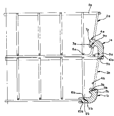
Fig. 1 is a side view of the tra~ stacking
system with crescent-shaped connectors positioned to
function as a connector and as a base for the bottom
tray.
Fig. 2 is a sectional view of the Fig. 1
takan along the axis 2-2.

2~3~ ~
DETAILED DESCRIPTION OF AN EMBODIMENT
Referring to Fig. 1, one side of the tray
stacking system is shown with two wire trays 2a and 2b
and two connectors la and lb. The top crescent-shaped
connector la is positioned to perform its connector
function. The connector head 7a clips onto the head
rung 3a. Supporting rung 4a provides support and
stabilizes the connector. Vertical rungs 12a help
prevent the crescent-shaped connector from moving in
the horizontal direction, and again act as stabilizers.
Connector end ~a is attached to top rung 5b of the
lower tray 2b.
Referring to Fig. 2, the upper connector la,
performing the connecting function, has formed in the
connector head 7a a head groove 9a which connects to
head rung 3a. The connector tail 8a has formed therein
a tail groove 10a which connects to the top rung 5b of
the lower tray 2b. When used as a connector, side
groove lla does not connect with a tray.
Lower connector lb, performing the base
function, also has a connector head 7b with head groove
9b connected with head rung 3b. When used as a base,
the lower connector lb is positioned about 900 in
relation to the position of the upper connector la.
Rung 4b does not contact the connector head when the
connector is used as a base. The lower connector tail
~b has a side groove llb which attaches to the base
rung 6b. When used as a base, tail groove 10b does not
connect with a tray.
Thus, while the invention has been described
with reference to a certain embodiment, those skilled
in the art will recognize modifications o~ structure,
arrangement, composition and the like that can be made
--3--

~3~ ~
to the present invention, but still fall within the
scope of the invention as hereafter claimed.

Representative Drawing
A single figure which represents the drawing illustrating the invention.
Administrative Status

2024-08-01:As part of the Next Generation Patents (NGP) transition, the Canadian Patents Database (CPD) now contains a more detailed Event History, which replicates the Event Log of our new back-office solution.

Please note that "Inactive:" events refers to events no longer in use in our new back-office solution.

For a clearer understanding of the status of the application/patent presented on this page, the site Disclaimer , as well as the definitions for Patent , Event History , Maintenance Fee  and Payment History  should be consulted.

Event History

Description Date
Inactive: IPC from MCD 2006-03-11
Time Limit for Reversal Expired 1994-04-10
Application Not Reinstated by Deadline 1994-04-10
Inactive: Adhoc Request Documented 1993-10-08
Deemed Abandoned - Failure to Respond to Maintenance Fee Notice 1993-10-08
Application Published (Open to Public Inspection) 1992-10-04
All Requirements for Examination Determined Compliant 1991-10-08
Request for Examination Requirements Determined Compliant 1991-10-08

Abandonment History

Abandonment Date Reason Reinstatement Date
1993-10-08
Owners on Record

Note: Records showing the ownership history in alphabetical order.

Current Owners on Record
FELLOWES MANUFACTURING COMPANY
Past Owners on Record
STANLEY GRESENS
Past Owners that do not appear in the "Owners on Record" listing will appear in other documentation within the application.
Documents

To view selected files, please enter reCAPTCHA code :


To view images, click a link in the Document Description column. To download the documents, select one or more checkboxes in the first column and then click the "Download Selected in PDF format (Zip Archive)" or the "Download Selected as Single PDF" button.

List of published and non-published patent-specific documents on the CPD .

If you have any difficulty accessing content, you can call the Client Service Centre at 1-866-997-1936 or send them an e-mail at CIPO Client Service Centre.


Document
Description 
Date
(yyyy-mm-dd) 
Number of pages   Size of Image (KB) 
Claims 1992-10-04 3 77
Cover Page 1992-10-04 1 12
Drawings 1992-10-04 2 34
Abstract 1992-10-04 1 13
Descriptions 1992-10-04 4 97
Representative drawing 1999-04-21 1 14