Note: Descriptions are shown in the official language in which they were submitted.
2053326
_
,
APPARATUS FOR SEPARATING COMMINGLING
HEAVIER AND LIGHTER IMMISCIBLE LIQUIDS
Summary Of The Invention
Apparatuses for use in separating commingled heavier and lighter immiscible
liquids have lon~ been utilized in the industry and particularly in the petroleum industry.
For background Information relating generally to the art of separating immiscible liquids,
reference may be had to the following United States Patents: 1,984,057; 2,598,746;
2,598,988; 2,701,620; 2,946,451; 3,672,511; 4,014,786; 4,299,703 and 4,603,000.
Heretofore the design of equipment for separating immiscible heavier and lighter
liquids has been based primarily on trial and error experimentation, rather than on sound
engineering principles. Many seemly well thought out designs have proven to be
inefficient and ineffective. Performance evaluation heretofore of known liquid/liquid
10 separators is typically accomplished only sporadically and then only after a system is
completed, in service, and performing poorly.
Liquid/liquid separators such as the designs represented by the above mentioned
U.S. Patents function with a limited degree of success and each has characteristics which
can achieve the separation of a heavier from a lighter immiscible liquid. However, none
15 of the devices shown in the prior art referenoes accomplish the separation of one
immiscible liquid from another at a rate of effectiveness which is desired in the industry
today.
2053326
In the past, the industry has not been as critically concerned with the completeness
of separation of heavier and lighter liquids, such as water from an oil emulsion. In today's
envu onment where concern is about reducing contamination and improving the quality
of the environment, it is more important than in the past that equipment be designed more
S ef~e~ively and efficiently to accomplish the separation of liquids, such as oiJ and water,
so ;3s to provide as near as possib'Q the ability to discharge water separated from an
erru dsion which has a degree of freedom of entrained lighter component, such as oil, than
h2s been acceptable in the past. The present invention is directed toward an improved
high~y effective apparatus for separating commingled heavier and lighter immiscible
10 liquids, and specifically such as commingled oil and water and even more specifically,
comn~ingled oil and water having gas entrained therein. Some of the unique features of
the irnmiscible liquid separator of the present invention include the following features:
1. A vessel tangential inlet is designed to impart centrifugal vortex shedding
motion to create a spiralling rise through a mixing chamber for repeated
contact and coalescing heavier liquids and solid contaminants.
2. A vertical mixing chamber within the vessel is divided into three distinct
sections for: (a) inlet fluid mixing: (b) free gas evolution in an isolated area
not continuous with the immiscible phase; and (c) an outlet conduit which
enhances hydraulic flow characteristics.
20~3326
_
3. Horizontal liquid flow distribution is utilized in an increasing radia! path and
decreasing velocity path at very close proximity to the liquid/liquid interface
for bulk separation.
4. Directional flow changes are achieved at below separation velocity with
distribution controlled to maximize hydraulic efficiency.
5. Vertical and downward flow is achieved to direct all settlable solids to the
vessel bottom for collection and removal.
6. A second ninety-plus degree liquid flow direction change from vertical to
horizontal around a second cone is achieved at below separation velocity
to ensure that all settlable solids actually settle from both the heavier and
lighter liquids before they are discharged.
These advantages are achieved in an apparatus for separating commingled heavier
and lighter immiscible liquids having an upright vessel with a commingled fluid inlet, a
heavier liquid outlet, a lighter liquid outlet and a gas outlet. A flow tube is positioned
oentrally within the vessel. A nOw inlet pipe connects the vessel commingled ~uid inlet to
the flow tube in a tangential manner to cause flow of the commingled fluid in a circular
pattern upwardly within the flow tube. The circular flow pattern is a key performance
design consideration.
2053326
A separating-liquids outlet is provided in the flow tube adjacent the top. An upper
spreader baffle is located within the vessel below the lighter liquid outlet.
By means of a concentric siphon tube a liquid/liquid interface is maintained within
the upward portion of the vessel and above the upper spreader baffle. By means of the
5 lighter liquid outlet a liquid/gas interface is maintained in the upper portion of the vessel
above the liquid/liquid interface. A gas outlet is provided for removing separated gas
from the interior of the vessel.
The flow tube has a heavier liquid inlet in the lower portion thereof. A lower
spreader baffle is positioned within the vessel and above the heavier liquid outlet in the
10 flow tube. The flow tube heavier liquid outlet is connected to the concentric siphon tube
so that the heavier liquid is withdrawn from the vessel.
In this manner the heavier liquid flow path provided within the vessel undergoes
first, a vertical upward vector, a radially horizontal vector within the upper portion of the
vessel and immediately below the liquid/liquid interface, a vertically downward vector
15 within the vesscl, a horizontal vector within the vessel below the spreader baffle and into
the liquid outlet. These flow direction reversals ensure more effective and efficient fluid
separation and the separation of both lighter and heavier entrained liquids and solids
within the vessel.
2053326
A better and a more complete understanding of the invention will be had by
reference to the following description and claims, taken in conjunct~on with the attached
drawings.
20~3326
(
Descrlptlon ot the Drawlngs
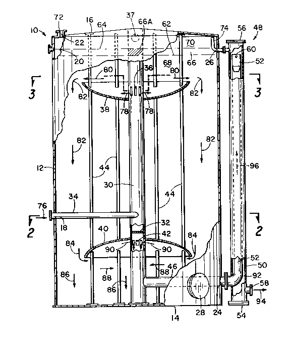
Figure 1 is an elevational view of a vessel shown broken away to reveal the interior
construction, the vessel incorporating the concepts of the present disclosure. The vessel
ind~des an adjacent concentric siphon tube externally of the vessel, the siphon tube
being also shown partially broken away to reveal interior features.
Figure 2 is a horizontal cross-sectional view taken along the line 2-2 of Figure 1
and showing details of the fluid inlet pipe with its tangential connection to the vertical flow
tube and showing the interior cross-sectional view of the concentric siphon tube.
Figure 3 is a cross-sectional view taken along the line ~-3 of hgure 2 and showing
the r~uid outlet of the vertical flow tube and also showing interior details of the concentric
1û siphon tube.
20~3326
Descrlptlon of the Pre~erred Embodiment
Referring to the drawings and first to Figure 1, an apparatus for separating
commingled heavier and lighter immiscible liquids is illustrated as a preferred means of
practicing the invention. The apparatus includes an upright vessel generally indicated by
the numeral 10. The vessel includes a cylindrical wall 12, a bottom 14 and top 16. The
5 vess~l is intended to be supported upon the earth or upon a foundation resting upon the
earth, the support not being shown.
Formed in the vessel wall 12 or top 16 is a commingled fluid inlet 18, a lighter
liquid outlet 20, a gas outlet 22, a heavier liquid outlet 24 and a pressure egu^' ~ation
opening 26. A manhole cover 28 is illustrated as a means for providing an access into
10 the lower portion of the vessel.
Positioned withln the Interlor of the vessel and preferably concentric with cylindrical
walls 12 is a vertical tlow tube 30. The interior of the flow tube is divided by a partition
32. A fluid inlet pipe 34 connects the fluid inlet opening 18 with the flow tube 30 above
part;tion 32. lllis connection is preferably tangential as shown in Figure 2.
The vertical flow tube 30 has, adj~cent the interior top of vessel 10, .iquid outlet
openin~s 36. These are preferably formed by vanes which can be achieved by cutouts
in flow tube 30, the vanes being indicated by the numeral 30A, as shown in Figure 3.
2053326
.
;
Above these vanes, and within the gas space, are gas outlets formed in the flow tube, the
gas outlets being indic~te-l by the numeral 37 in Figure 1.
Supported within the vessel in the upper portion thereof is an upper spreader baffle
38 which is generally horizontally extending, the baffle being immediately below the fluid
5 out~et openings 36.
In like manner, a lower spreader bame 40 is supported within the vessel below the
fluid inlet pipe 34 and above liquid outlet opening 42 formed in the flow tube 30.
Vertical structural members 44 are positioned within the vessel to support upward
and lower baffles 38 and 40, the structural members not being involved in the fluid flow
10 patterns.
A liquid outlet pipe 46 communicates with the flow tube 30 below the liquid outlet
openings 42 and extends through the heavier liquid outlet 24.
Positioned exteriorly of vessel 10 is a vertical concentric siphon tube, generally
in~cated by the numeral 48. The siphon tube includes an exterior tube 50, a smaller
15 diameter concentric interior tube 52 which is connected at its lower end with liquid outlet
pipe 46. The exterior tube 50 has a bottom 54 and a closed top 56. Exterior tube 50
has, adjacent the bottom, a heavier liquid outlet 58 having means for connection to piping
whereby the separated heavier liquid is carried away from the apparatus.
2053326
The interior tube 52 of the concentric siphon system has a top 60 which is placed
bel~ the exterior tube top 56. The height of top 60 of interior tube 52 provides the level
of a Gquid/liquid interface 62 within the interior of the vessel 10. rhe means whereby this
is aocomplished will be discussed later in connection with the disaJssion of the tlow paths
5 of fllJid within the system.
A liquid/gas interface 64 is established within vessel 10 by the location of the
lighter liquid outlet 20 in the vessel. Between the liquid/liquid interface 62 and the
liqui~/gas interface 64 is a horizontal layer of lighter liquid 66. The lighter liquid within
flow tube 30 is indicated by 66A in Figure 1. Below the liquid/liquid interface 62 within
10 the interior of the vessel and exterior of flow tube 30, the vessel is filled with heavier liquid
68. Above the liquid/gas interface 64 the interior of the vessel contains gas 70.
A gas outlet pipe 72 connected to the top 16 of the vessel in communication with
the gas outlet opening 22 provides means for connection to piping by which gas
separatr~d from the fluids within the vessel is carried away ~rom the apparatus.
A pressure equalization pipe 74 connects with the interior of the ooncentric siphon
exterior tube 50 below the top 56 and above the upper end 60 of the interior tube 52 and
extends through the pressure equalization opening 26. The pressure equali7~tion t~be
74 terminates within the vessel in the upper pOnion thereof wherein a gas 70 collects.
2053326
,
The apparatus of the system having been described, the flow paths will now be
disc~ssed. Commingled fluids consisting of solids and heavier and lighter liquids, with
or w~thout commingled gas, enters the vessel as indicated by the arrow 76 in Figures 1
and 2. The fluid entry is into the fluid inlet pipe 34. The commingled fluid flo~s through
5 pipe 34 and tangentially enters the interior of flow tube 30, the flow path being in a
swirfing pattern indicated by arrow 76 within the interior of the flow tube above the
parfflion 32. This tangential interconnection between the fluid inlet pipe 34 and flow tube
30 is designed to impart centrifugal vortex shedding motion to the liquid/liquid emulsion
to create a spirallin~ flow path rise within the flow tube 30, as indicated by the arrow 76.
10 This spiralling flow path rise within tube 30 provides an area of coalesdng of the
liquid/liquid emulsion within the flow tube.
The fluid and solids rise within the flow tube 30 and exits the flow tube through the
fluid outlet openings 36, as indicated by arrow 78 and as seen in hgures 1 and 3. The
fluids and solids, having exited through openings 36, indicated by arrows 78, flow
15 generally horizontally and radially outwardly, as indicated by the arrows 80. This
horizontal flow is at a decreasing rate and Tncreasing radius and is directly below the
liquid/liquid interface 62 and permits the separation of the lighter from the heavier liquid,
the aghter liquid rising above the interface 62 so that the lighter liquid 66 collects above
the interface 62 and heavier liquid 68 remains below the interfaoe.
2053326
The heavier liquid, after passing upper spreader baffle 38, turns vertically
do~nward as indicated by the arrows 82. This downward vertical migration within the
intenor of the vessel 10 provides ample time for any commingled lighter fluid to be
separated therefrom and to rise above the liquid/liquid interface 62. Any gas separated
5 frorn the commingled liquid is permitted to escape and pass upwardly through the lighter
flu~ 66 and 66A within flow tube 30. The separated gas collects at 70 above the
li~u~d/gas interface 64. The cs"Qcted gas is drawn from the interior of the vessel through
the gas outlet 72 and carried away in piping connected to the ~as outlet pipe 72.
The downward flow of heavier liquid, as indicated by the arrow 82, continues until
10 a h~avier liquid reaches the lower spreader baffle 40. At this stage in the flow path the
he~ier liquid undergoes a transition from downward vertical to horizontal, as in~;cated
by arrows 84 indicating the flow direction change. This radical flow direction change
cal~es any entrained solid particles to drop out and to be discharged downwardly
vert~cally into the interior bottom of the vessel, as indicated by arrows 86.
The heavier liquid, after moving vertically downwardly and changing directions to
flow inward horizontally, as indicated by the arrows 84, then moves in a horizontal path
inwardly below baffle 40, as indicated by arrows 88. The heavier liquid flows under the
lower spreader ba~e 40 and enters the liquid outlet openings 42, as indicated by the
arrows 90. The heavier liquid flows downwardly within the flow tube 30 below partition
20 32 and into the interior of liquid outlet pipe 46. The heavier liquid flows vertically upwardly
20~3326
within the interior tube 52 and out the upper end 60 thereof. The heavier liquid then flows
downwardly in the annular area 92 and out the heavier liquid outet 58, as indicated by
arrow 94. The upward flow of heavier liquid within the inner tube 52 is indicated by arrow
96.
Thus, it can be seen that the unique flow path arrangement of the apparatus for
separating lighter and heavier immiscible liquids and entrained gas is designed to provide
maumum effect and efficient separation within the vessel. The flow path is such as to
conduct the commingled heavier and lighter immiscible liquids horizontally at descending
10 radial flow rates immediately below the liquid/liquid interface in the upper portion of the
ves~el to permit the lighter liquid to separate and enter the lighter liquid area to be
withdrawn from the vessel. Gas escaping from the commingled liquids is withdrawn from
the upper end of the vessel. The heavier liquid is conducted in a manner to provide flow
direction changes, such as to augment the separation of any entrained heavier or lighter
15 solids. The heavier solids being discharged downwardly into the interior of the vessel.
The claims and the specification describe the invention presented and the terms
that are employed in the claims draw their meaning from the use of such terms in the
spec`ification. The same terms employed in the prior art may be broader in meaning than
spec7fically employed herein. Whenever there is a question between the broader definition
20 of such terms used in the prior art and the more specific use of the terms herein, the
more specific meaning is meant.
2053326
While the invention has been described with a certain degree of particularity, it is
man;~est that many changes may be made in the details of construction and the
arrar.gement of components without departing from the spirit and scope of this disclosure.
It is understood that the invention is not limited to the embodiments set forth herein for
5 purposes of exemplification, but is to be limited only by the scope of the attached claim
or cl~ims, including the full range of equivalency to which each element thereof is entitled.
13