Language selection

Search

Patent 2053486 Summary

Third-party information liability

Some of the information on this Web page has been provided by external sources. The Government of Canada is not responsible for the accuracy, reliability or currency of the information supplied by external sources. Users wishing to rely upon this information should consult directly with the source of the information. Content provided by external sources is not subject to official languages, privacy and accessibility requirements.

Claims and Abstract availability

Any discrepancies in the text and image of the Claims and Abstract are due to differing posting times. Text of the Claims and Abstract are posted:

  • At the time the application is open to public inspection;
  • At the time of issue of the patent (grant).
(12) Patent Application: (11) CA 2053486
(54) English Title: FISHING LURE
(54) French Title: APPAT DE PECHE
Status: Deemed Abandoned and Beyond the Period of Reinstatement - Pending Response to Notice of Disregarded Communication
Bibliographic Data
Abstracts

English Abstract


- 8 -
FISHING LURE
ABSTRACT OF THE DISCLOSURE
A fishing lure has a lure body carrying two
fixed hooks and a safety pin at the trailing end, with
all three components projecting to the top of the lure
body. The safety pin is located between the two upwardly
divergent hooks and serves to engage a minnow with the
lure. A ring is fitted on the hook shanks and on the
safety pin for free movement and carries a moveable
trailing hook that is, in use, engaged with the tail of a
minnow carried by the lure. The moveable hook does not
restrict movements of the minnow but acts to hook any
nibbling fish. The safety pin acts as a retainer
retaining the moveable hook carrying ring on the lure.


Claims

Note: Claims are shown in the official language in which they were submitted.

- 6 -
CLAIMS
(1) A fishing lure comprising:
(a) lure body;
(b) a plurality of fixed hooks secured rigidly
to the body and projecting from a trailing end of the
body;
(c) a safety pin secured rigidly to the body
and having a bight projecting rearwardly from the trail-
ing end of the body adjacent the plurality of fixed
hooks;
(d) a ring surrounding the fixed hooks and
engaging the bight of the safety pin and being moveable
on the hooks and safety pin; and
(e) a moveable hook carried by the ring.
(2) A fishing lure according to Claim 1 wherein the
fixed hooks comprise two fixed hooks with shanks arranged
side-by-side and bends diverging away from the shanks.
(3) A fishing lure according to Claim 2 wherein the
bends of the fixed hooks diverge at an angle less than 90
degrees.
(4) A fishing lure according to Claim 2 wherein the
safety pin comprises a fixed shank arranged side-by-side
with the shanks of the fixed hooks, a return bend at the
trailing end of the fixed shank, a return shank extending

- 7 -
forwardly from the return bend and a return shank retain-
er projecting from the body and selectively engageable
with the return shank.
(5) A fishing lure according to Claim 4 wherein the
retainer is a hook.
(6) A fishing lure according to any one of the
preceding claims wherein the ring is a split ring.
(7) A fishing lure according to anyone of the pre-
ceding claims wherein the moveable hook is a single
hook.
(8) A fishing lure according any one of the preced-
ing claims wherein the moveable hook is a treble hook.
(9) A fishing lure according to Claim 1 wherein the
lure body comprises an enlarged head.
(10) A fishing lure according to Claim 1 wherein the
lure body comprises line engaging means for securing a
line to the lure body.
(11) A fishing lure according to Claim 10 wherein
the line engaging means comprise an eye on an upper
surface of the body.
(12) A fishing lure according to Claim 11 wherein
the safety pin extends to the upper side of the body.
(13) A fishing lure according to Claim 12 wherein
the fixed hooks extend to the upper side of the body.

Description

Note: Descriptions are shown in the official language in which they were submitted.


~ 2~53~
-- 1 --
F I S H I NG LURE
The present invention relates to a fishing
lure and more particularly to a multi-hook lure for
carrying bait, especially minnows.
Many fishing lures have been proposed in the
past. These have enjoyed varying degrees of success.
The present inventlon is concerned wlth the provislon of
a novel minnow-carrying lure that is intended to hook not
only fish making a full strike at the lure and the
carryied bait but also fish nibbling on the bait.
According to the present invention there is
provided a fishing lure comprising:
(a) lure body;
(b) a plurality of fixed hooks secured rigidly
to the body and projecting from a trailing end of the
body;
(c) a safety pin secured rigidly to the body
and having a bight pro;ecting rearwardly from the trail-
ing end of the body adjacent the plurality of fixed
hooks;
(d) a ring surrounding the fixed hooks and
engaglng the bight of the safety pin and being moveable
on the hooks and safety pin; and

~ ` 2~53~g6
(e) a moveable hook carried by the ring.
In preferred embodiments of the invention, the
lure body has an eye on the upper surface for connection
to a fishing line. The safety pin and fixed hooks also
project to the upper side of the body.
In use, a minnow is engaged on the safety pin,
with the head of the minnow at the leading end of the
pin and the body between the fixed hooks. The trailing
hook is then engaged with the tail of the minnow.
The trailing hook is especially effective in
hookin~ nibbling fish as it is set into the tail of the
minnow. Because it is mobile, it does not unduly
restrict the movements of the minnow tail as the lure is
drawn through the water. The safety pin serves two main
functions, first to secure the minnow on the lure,
between the fixed hooks, and second as an anchor for the
ring carrying the moveable trailing hook. When a fish is
caught by the trailing hook only, the hook and the ring
carrying it will be pulled along the shanks of the fixed
hooks and the saEety pin If the ring is not engaged
with the safety pin, it will tend to bend the two fixed
hooks towards one another, creating a situation in which
the ring could potentially be released from the fixed

20~3~6
hooks. Engagement of the ring on the safety pin prevents
this.
In the accompanying drawings, whlch illustrate
an exemplary embodiment of the present invention.
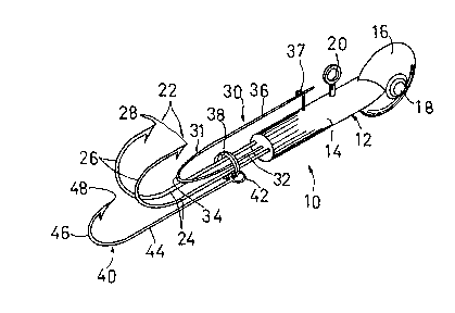
Figure 1 is a isometric representation of a
fishing lure according to the present invention;
Figure 2 is a side elevation of the lure of
Figure 1;
Figure 3 is a plan view of the lure; and
Figure 4 is a rear elevation of the lure.
Referring to the accompanying drawings, there
is illustrated a fishing lure 10 having a body 12. The
body includes a cylindrical stem 14 and an enlarged
vertically oriented circular head 16 at the leadin~ end
of the stem. The head is equipped with simulated eyes 18
on its opposite sides. On the top of the stem, behind
the head 16 is an eye 20 for use in connecting the lure
to a line or leader (not shown). At the trailing end of
the stem 14 are two hooks 22 with side-by-side shanks 24
secured rigidly to the stem 14 of the lure body. Each
shank leads to a bend 26 in the respective hook, which in
turn leads to a free end 28 which is sharpened and
barbed. The bends of the hook diverge away from the
shanks 24, at an angle less than 90. As discussed in

~3~36
-- 4
the following, this accomodates the body of a minnow in
the "V" between the hooks.
Between the fixed hooks 22 is a safety pin 30.
This includes a bight 31 consisting of a shank 32 fixed
to the trailing end of the stem 14 and extending rear-
wardly along side the shanks 24 of the hooks 22. At the
trailing end of the shank 32 is a return bend 34 that
leads into a return shank 36 extending forwardly from the
bend. The bight 31 is made of a spring wire and has a
normal position with the return shank 34 sloping upwardly
and to the front of the lure. In an engaged position,
the return shank 36 extends forwardly from the bend 34
and is engaged with a retainer 37 in the form of a hook
secured to the body 12 of the lure.
A split ring 38 is carried by the shanks 24 of
the flxed hooks 22 and the fixed shank 32 of the safety
pin. It is sufficiently large to be a loose fit on the
shanks so that it can move freely on them. The ring 38
carries a trailing hook 40 that engages on the split ring
with an eye 42 at the end of the shank 44 of the hooks.
The hook has a shank 44 leading from the eye, and a bend
46 leading to a free end 48 that is sharpened and
barbed.

53~6
AS illustrated most particularly in Figure 2,
the lure ls designed to carry a minnow impaled on the
safety pin with the head of the minnow adjacent the eye
20 and the retainer 37. The body of the minnow is sup-
ported between the fixed hooks 22, while the moveable
trailing hook 40 hooks into the tail of the minnow. The
trailing hook is free is to move with the minnow's tail
so as not unduly to restrict the movement of the bait.
As noted above, the safety pin has two primary
functions, securing the minnow to the lure; and anchoring
the split ring 38 to the body so that the split ring will
not bend the hooks 22 and disengage from them.
While one embodiment o~ the present invention
has been descrlbed in the foregoing, it is to be under-
stood that other embodiments are possible within the
scope of the invention. For example, the line may carry
more than two fixed hooks. The movable hook may be a
multiple hook, for example a treble hook. The invention
is therefore to be considered limited solely by the scope
of the appended claims.
. . .

Representative Drawing
A single figure which represents the drawing illustrating the invention.
Administrative Status

2024-08-01:As part of the Next Generation Patents (NGP) transition, the Canadian Patents Database (CPD) now contains a more detailed Event History, which replicates the Event Log of our new back-office solution.

Please note that "Inactive:" events refers to events no longer in use in our new back-office solution.

For a clearer understanding of the status of the application/patent presented on this page, the site Disclaimer , as well as the definitions for Patent , Event History , Maintenance Fee  and Payment History  should be consulted.

Event History

Description Date
Time Limit for Reversal Expired 1999-10-15
Application Not Reinstated by Deadline 1999-10-15
Deemed Abandoned - Failure to Respond to Maintenance Fee Notice 1998-10-15
Inactive: Abandon-RFE+Late fee unpaid-Correspondence sent 1998-10-15
Application Published (Open to Public Inspection) 1993-04-16

Abandonment History

Abandonment Date Reason Reinstatement Date
1998-10-15

Maintenance Fee

The last payment was received on 1997-09-25

Note : If the full payment has not been received on or before the date indicated, a further fee may be required which may be one of the following

  • the reinstatement fee;
  • the late payment fee; or
  • additional fee to reverse deemed expiry.

Patent fees are adjusted on the 1st of January every year. The amounts above are the current amounts if received by December 31 of the current year.
Please refer to the CIPO Patent Fees web page to see all current fee amounts.

Fee History

Fee Type Anniversary Year Due Date Paid Date
MF (application, 6th anniv.) - small 06 1997-10-15 1997-09-25
Owners on Record

Note: Records showing the ownership history in alphabetical order.

Current Owners on Record
W. EDWARD ISAAC
Past Owners on Record
None
Past Owners that do not appear in the "Owners on Record" listing will appear in other documentation within the application.
Documents

To view selected files, please enter reCAPTCHA code :


To view images, click a link in the Document Description column. To download the documents, select one or more checkboxes in the first column and then click the "Download Selected in PDF format (Zip Archive)" or the "Download Selected as Single PDF" button.

List of published and non-published patent-specific documents on the CPD .

If you have any difficulty accessing content, you can call the Client Service Centre at 1-866-997-1936 or send them an e-mail at CIPO Client Service Centre.


Document
Description 
Date
(yyyy-mm-dd) 
Number of pages   Size of Image (KB) 
Abstract 1993-04-15 1 16
Drawings 1993-04-15 2 38
Claims 1993-04-15 2 47
Descriptions 1993-04-15 5 124
Representative drawing 1998-09-23 1 12
Reminder - Request for Examination 1998-06-15 1 117
Courtesy - Abandonment Letter (Maintenance Fee) 1998-11-11 1 184
Courtesy - Abandonment Letter (Request for Examination) 1998-11-25 1 171
Fees 1996-09-23 1 43
Fees 1995-10-03 1 36
Fees 1994-10-04 1 33
Fees 1993-09-13 1 34
Courtesy - Office Letter 1995-09-14 1 38
Examiner Requisition 1997-06-16 2 117