Language selection

Search

Patent 2053722 Summary

Third-party information liability

Some of the information on this Web page has been provided by external sources. The Government of Canada is not responsible for the accuracy, reliability or currency of the information supplied by external sources. Users wishing to rely upon this information should consult directly with the source of the information. Content provided by external sources is not subject to official languages, privacy and accessibility requirements.

Claims and Abstract availability

Any discrepancies in the text and image of the Claims and Abstract are due to differing posting times. Text of the Claims and Abstract are posted:

  • At the time the application is open to public inspection;
  • At the time of issue of the patent (grant).
(12) Patent: (11) CA 2053722
(54) English Title: CUTTING DEVICE
(54) French Title: DISPOSITIF DE COUPE
Status: Expired and beyond the Period of Reversal
Bibliographic Data
(51) International Patent Classification (IPC):
  • B26D 1/00 (2006.01)
  • B26D 1/04 (2006.01)
  • B26D 1/09 (2006.01)
  • B26D 7/00 (2006.01)
  • B26D 7/08 (2006.01)
(72) Inventors :
  • HARROP, MARTIN (United Kingdom)
  • RAWSON, FRANCIS FREDERICK HAMILTON (United Kingdom)
(73) Owners :
  • SOCIETE DES PRODUITS NESTLE S.A.
(71) Applicants :
  • SOCIETE DES PRODUITS NESTLE S.A. (Switzerland)
(74) Agent: BORDEN LADNER GERVAIS LLP
(74) Associate agent:
(45) Issued: 2000-05-23
(22) Filed Date: 1991-10-18
(41) Open to Public Inspection: 1992-04-20
Examination requested: 1998-05-01
Availability of licence: N/A
Dedicated to the Public: N/A
(25) Language of filing: English

Patent Cooperation Treaty (PCT): No

(30) Application Priority Data:
Application No. Country/Territory Date
9022844.6 (United Kingdom) 1990-10-19

Abstracts

English Abstract


1. A cutting device comprising an ultrasonic vibrating
device and a cutting blade mounted on the device so as
to be vibrated thereby/therewith, the blade lying in a
plane extending transversely to the longitudinal axis of
vibration wherein the vibrating device comprises two or
more support members, the cutting blade being supported
by two adjacent support members.


Claims

Note: Claims are shown in the official language in which they were submitted.

-6-
THE EMBODIMENTS OF THE INVENTION IN WHICH AN EXCLUSIVE
PROPERTY OR PRIVILEGE IS CLAIMED ARE DEFINED AS FOLLOWS:
1. A cutting device comprising an ultrasonic vibrating
device and a cutting blade mounted on the device so as
to be vibrated thereby/therewith, the blade lying in a
plane extending transversely to the longitudinal axis of
vibration wherein the vibrating device comprises two or
more support members, the cutting blade being supported
by two adjacent support members.
2. A cutting device according to claim 1 wherein the
blade is secured at its ends to the adjacent support
members.
3. A cutting device according to claim 1 in which the
blade lies in a plane at right angles to the longitudinal
axis of vibration.
4. A cutting device according to claim 1 wherein the
support members are vibrated by the device, and the
support members comprise a plurality of blades, each lying
in one of a plurality of parallel planes.
5. A cutting device according to claim 1 wherein the
blades are located at anti-nodes of the support members.
6. A cutting device according to claim 1 wherein the
blades are rectangular in shape having a length of from
to 100 mm and a width of from 1 to 22 mm.
7. A cutting device according to claim 6 wherein the
blades are narrower along a portion of their lengths
then at their ends.
8. A cutting device according to claim 1 wherein the
thickness of the cutting blades is from 0.25 to 1 mm.

-7-
9. A cutting device according to claim 1 wherein some at
least of the support members are secured to the vibrating
device through the intermediary of node/anti-node
displacement devices.
10. A cutting device according to claim 1 which
comprises a vibrating mechanism to which the support
members are secured, the vibrating mechanism being in
the form of a horn, one surface of which is caused to
vibrate at ultrasonic frequency.
11. A method of cutting an article involving mounting a
cutting blade on an ultrasonic vibrating device in a
manner such that the blade lies in a plane extending
transverse to the longitudinal axis of vibrations, and
moving said blade in said plane through said article,
wherein the vibrating device comprises two or more
support members, the cutting blade being supported by two
adjacent support members.

Description

Note: Descriptions are shown in the official language in which they were submitted.


CA 02053722 1999-07-14
s
Cutting device
This invention is concerned with improvements relating
to cutting, particularly by a method involving the use
of high frequency (ultrasonic) vibration devices.
The conventional method of ultrasonic cutting involves
the use of a cutting blade which is mounted on an ultra-
sonic vibrating device with the blade lying in a plane
containing the longitudinal axis of vibrations, and mo-
ving the blade through the article to be cut in said
plane.
Difficulty is experienced using conventional methods in
that the depth of cut which is attainable is limited.
For this reason ultrasonic cutting has in general been
limited to thin articles, such as paper, cloth and thin
plastic sheets. A significant problem exists in cutting
blocks of substantial depth, and/or in providing a num-
ber of parallel cuts simultaneously.
Difficulty is also experienced in cutting materials
which are brittle, e.g. honeycomb or crystalline mate-
rials.
In our EP 353,415 there is described and
claimed a method and apparatus for cutting an article
involving mounting a cutting blade on an ultrasonic
vibrating device in a manner such that the blade lies in
a plane extending transverse (preferably at right
angles) to the longitudinal axis of vibrations, and
moving said blade in said plane through said article.
In this manner the blade moves back and forth transverse
to the plane in which it moves through the article,.ef -
fecting a removal of the material of the article along
the line of cut. In one embodiment of the invention of
EP 353,415, the vibrating device comprises one or

CA 02053722 1999-07-14
- 2 -
more support members which are vibrated by the device,
each support member supporting a plurality of blades.
In the specific embodiments described in the detailed
description as illustrated in the drawings of
EP 353,415, each blade is secured to a single sup-
port member at its centre.
We have now found that a cutting method and device fal-
ling within the claims of EU-A-89109488.0 where the
blade is secured to adjacent support members, provides
significantly more cutting power than where the blade is
secured to a single support member.
Accordingly the present invention provides a cutting
device comprising an ultrasonic vibrating device and a
cutting blade mounted on the device so as to be vibrated
thereby/therewith, the blade lying in a plane extending
transversely to the longitudinal axis of vibration
wherein the vibrating device comprises two or more sup-
port members, the cutting blade being supported by two
adjacent support members.
Advantageously, the blade is secured at its ends to the
adjacent support members. Preferably the blade lies in a
plane at right angles to the longitudinal axis of
vibration.
The support members are vibrated by the device, and each
support member may comprise a, plurality of blades, each
lying in one of a plurality of parallel planes,
desirably the blades being located at anti-nodes of the
support member.
The blades are conveniently made of steel e.g. graphite
impregnated steel or tempered high tensile steel. They
could be coated with chrome or polytetrafluoroethylene
which may impart a non-stick surface. The cutting edge

3 203722
of the blade may be spark-eroded or otherwise cut to
produce a hollow edge.
The blades may be wide, narrow, thin or they may be
wires. They may be round, triangular or roughly square
in shape but preferably rectangular e.g. from 10 to 100
mm long and from 1 to 22 mm wide. When the blades are
roughly square or rectangular in shape, they are
advantageously profiled so that they are narrower along
a portion of their lengths than at their ends. For
example, from 40a to 90% and preferably from 50% to 70%
of their length between the ends is narrower and the
width may be up to 60% less than at the ends. The
thickness of the blades may be from 0.25 to 1 mm and
more usually from 0.3 to 0.6 mm, especially from 0.35 to
0.45 mm.
Some at least of the support members may be secured to
the vibrating device through the intermediary of
node/anti-node displacement devices.
Preferably the device comprises a vibrating mechanism to
which the support member or support members are secured,
the vibrating mechanism being in the form of a horn,
preferably cylindrical or rectangular in shape, one
surface of which is caused to vibrate at ultrasonic fre-
quency.
The number of support members is only limited by
practical considerations and there may be, for instance,
up to 20 support members
The present invention also provides a method of cutting
an article involving mounting a cutting blade on an
ultrasonic vibrating device in a manner such that the
blade lies in a plane extending transverse to the
longitudinal axis of vibrations, and moving said blade
in said plane through said article, wherein the

- 4 -
203722
vibrating device comprises two or more support members,
the cutting blade being supported by two adjacent
support members.
The movement of the blade relating to the article to be
cut may, if desired, be achieved by moving the article
through the blade. However, it is also possible to move
the blade through the article to be cut.
The present invention will now be further illustrated by
way of example only with reference to the accompanying
drawings in which
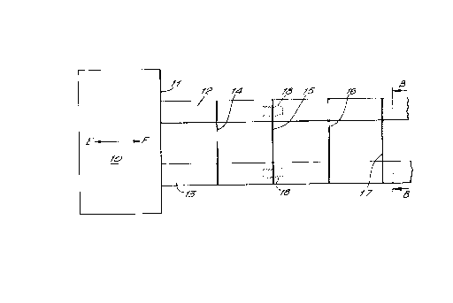
Figure 1 represents a diagramanatic side sectional view
of a cutting device according to the
invention,
Figure 2 represents a view of a blade of Figure 1
looking in the direction of the arrows B-B,
and
Figure 3 represents an alternative shape of the blade
of Figure 2.
The device which is the preferred embodiment of this
invention comprises a vibrating device 10 in the form
of a cylindrical or rectangular shaped mother horn, the
front face 11 of which is vibrated at ultrasonic
frequency in the longitudinal direction E-F, the face 11
representing an anti-node of the device. Connected to
the front face 11 are two or possibly several pairs of
supporting devices 12 and 13 extending in the
longitudinal direction E-F.
Mounted at spaced intervals between the supporting
members 12 and 13 are blades 14, 15, 16 and 17. Each
blade is connected at each end to the support member by
an internal stud fastening 18 which passes through the

- 5 -
205~~2~
apertures 19. The blades are 0.38 mm thick, 15 mm wide
and 90 mm long.
The cutting blades lie in a plane extending at right
angles to the longitudinal axis of the support member,
and are located on the support members at spaced
anti-nodes. Thus in use, the blades will vibrate in a
complicated mode, primarily in the direction E-F, and on
passage through the article to be cut, will excavate a
cut from the article, as the blade passes through the
article.
When the device is moved relative to the article to be
cut, relative movement taking place in a direction at
right angle to the longitudinal axis E-F, with the
blades moving in the planes in which they lie, the
article may be cut simultaneously by a plurality of cut
lines.
25
35

Representative Drawing
A single figure which represents the drawing illustrating the invention.
Administrative Status

2024-08-01:As part of the Next Generation Patents (NGP) transition, the Canadian Patents Database (CPD) now contains a more detailed Event History, which replicates the Event Log of our new back-office solution.

Please note that "Inactive:" events refers to events no longer in use in our new back-office solution.

For a clearer understanding of the status of the application/patent presented on this page, the site Disclaimer , as well as the definitions for Patent , Event History , Maintenance Fee  and Payment History  should be consulted.

Event History

Description Date
Time Limit for Reversal Expired 2007-10-18
Letter Sent 2006-10-18
Inactive: IPC from MCD 2006-03-11
Grant by Issuance 2000-05-23
Inactive: Cover page published 2000-05-22
Inactive: Final fee received 2000-02-22
Pre-grant 2000-02-22
Notice of Allowance is Issued 1999-08-30
Letter Sent 1999-08-30
Inactive: Approved for allowance (AFA) 1999-08-12
Amendment Received - Voluntary Amendment 1999-07-14
Amendment Received - Voluntary Amendment 1999-04-28
Letter Sent 1998-05-29
Inactive: Application prosecuted on TS as of Log entry date 1998-05-28
Inactive: Status info is complete as of Log entry date 1998-05-28
Request for Examination Requirements Determined Compliant 1998-05-01
All Requirements for Examination Determined Compliant 1998-05-01
Application Published (Open to Public Inspection) 1992-04-20

Abandonment History

There is no abandonment history.

Maintenance Fee

The last payment was received on 1999-09-17

Note : If the full payment has not been received on or before the date indicated, a further fee may be required which may be one of the following

  • the reinstatement fee;
  • the late payment fee; or
  • additional fee to reverse deemed expiry.

Please refer to the CIPO Patent Fees web page to see all current fee amounts.

Fee History

Fee Type Anniversary Year Due Date Paid Date
MF (application, 6th anniv.) - standard 06 1997-10-20 1997-09-22
Request for examination - standard 1998-05-01
MF (application, 7th anniv.) - standard 07 1998-10-19 1998-09-17
MF (application, 8th anniv.) - standard 08 1999-10-18 1999-09-17
Final fee - standard 2000-02-22
MF (patent, 9th anniv.) - standard 2000-10-18 2000-09-19
MF (patent, 10th anniv.) - standard 2001-10-18 2001-09-18
MF (patent, 11th anniv.) - standard 2002-10-18 2002-09-19
MF (patent, 12th anniv.) - standard 2003-10-20 2003-09-17
MF (patent, 13th anniv.) - standard 2004-10-18 2004-09-09
MF (patent, 14th anniv.) - standard 2005-10-18 2005-10-14
Owners on Record

Note: Records showing the ownership history in alphabetical order.

Current Owners on Record
SOCIETE DES PRODUITS NESTLE S.A.
Past Owners on Record
FRANCIS FREDERICK HAMILTON RAWSON
MARTIN HARROP
Past Owners that do not appear in the "Owners on Record" listing will appear in other documentation within the application.
Documents

To view selected files, please enter reCAPTCHA code :


To view images, click a link in the Document Description column. To download the documents, select one or more checkboxes in the first column and then click the "Download Selected in PDF format (Zip Archive)" or the "Download Selected as Single PDF" button.

List of published and non-published patent-specific documents on the CPD .

If you have any difficulty accessing content, you can call the Client Service Centre at 1-866-997-1936 or send them an e-mail at CIPO Client Service Centre.


Document
Description 
Date
(yyyy-mm-dd) 
Number of pages   Size of Image (KB) 
Cover Page 2000-05-01 1 26
Cover Page 1993-11-02 1 11
Abstract 1993-11-02 1 10
Description 1993-11-02 5 155
Claims 1993-11-02 2 51
Drawings 1993-11-02 1 14
Representative drawing 2000-05-01 1 5
Representative drawing 1999-04-22 1 9
Description 1999-07-14 5 175
Acknowledgement of Request for Examination 1998-05-29 1 178
Commissioner's Notice - Application Found Allowable 1999-08-30 1 163
Maintenance Fee Notice 2006-12-13 1 173
Correspondence 2000-02-22 1 28
Fees 1996-09-20 1 70
Fees 1995-08-08 1 69
Fees 1994-07-14 1 84
Fees 1993-08-20 1 39