Note: Descriptions are shown in the official language in which they were submitted.
2~3~
Carbon-containi~g~sgEe~ite material part protected against ox dation
and its ~roduction ~ocess.
DESCRIPTION
.
The present invention relates to a carbon-containing composite mate-
rial part, which is made uno~idizable up to a temperature of 2000C
for long periods (several hundred hours), as well as to its produc-
tion process.
Carbon-containing composite material parts can be used in numerous
industrial fields and in particular in the space field, as a result
of their low weight, for the production of reusable space vehicles
(shuttles or aircraft). These parts must be able to resist the
heating caused by the friction of the air during the high speed
reentry of the space craft into the atmosphere.
These space craft are in particular those whose reentry missions
lead to exposure to high temperatures (1800C under an air pressure
of 0.1 to 10 kPa) or lead to the exposure of certain parts to vari-
able temperatures (1000 to 1800C) at certain points which are more
highly stressed than others such as the nose, ailerons and leading
edges.
However, the invention also applies in other industrial fields requi-
ring the use of refractory material parts maintaining good mechanical
properties above 1100C in a corrosive medium. This is in particular
the case with turbomotors having an improved efficiency operating
at high temperatures (1300 to 1400C) and certain industrial heat
recuperators~
Carbon-containing materials which are protected against oxidation
and to which the present invention applies are composite materials
constituted by carbon-containing fibres embedded in a carbon-containing
SP 6534.69 LC
7 ~ 2
matrix and in particular materials of the carbon-carbon type.
The main problem of composite materials of the carbon-carbon type
is their oxidation in air at high temperature leading to the trans-
formation of the carbon into carbon oxide and therefore to a deter-
ioration over time of the composite materials.
In order to avoid this oxidation, various processes have already
been envisaged concerning the protection of these materials and
based on the use of a silicon carbide coating formed on the outer
surface of the composite material parts. This outer SiC coating
can be produced by chemical phase vapour deposition (CPVD) by crac-
king chlorosilane alone or associated with hydrogen and/or hydro-
carbons or can be obtained by siliciding the surface carbon of the
composite material. These two deposition methods are in particular
described in FR-A-2 611 198 filed by the present Applicant.
Surface siliciding is carried out by "PACK-cementation" by immersing
the part to bP silicided in a mixture of powders which, by heating,
gives off vapours of siliciding species such as silicon or silicon
monoxide.
Other methods combine the siliclding of the surface carbon of the
part with a chemical phase vapour deposition (cf. US-A-3 406 044,
US-A-4 425 407 and US-A-4 476 178).
All these methods for producing a SiC layer on composite materials
of the carbon-carbon type lead to a cracked layer, as a result of
the difference of the thermal expansion coefficients between the
carbon containing material and the silicon carbide. In order to
obviate this disadvantage, a number of different filling materials
have been envisaged (cf. FR-A-2 611 198 and FR-A-2 635 773).
Moreover, the methods involving the deposition of SiC by CPVD lead
SP 6534.69 LC
2~37~2
to an outer coating having a relatively mediocre adhesion, which
can lead to the separation of this coating under normal conditions
of use of parts protected by this coating, which is not the case
with an outer coating obtained by siliciding. Moreover, during
the production of this carbon-containing material, microcracks are
created within the material.
The invention relates to a process for producing a carbon-containing
composite material part, whose protection against oxidation is impr-
oved compared with that of the prior art. This part is able to
withstand very high temperatures under reduced pressures.
In order to improve the oxidation resistance of the carbon-containing
composite material parts, the Applicant has envisaged controlling
the cracks of the outer coating by imposing preferred directions
thereon with respect to the main directions of the underlying comp-
osite material.
As the problem of cracks in the SiC coating occurs for all ceramics
having a higher thermal expansion coefficient than that of the carb-
on-containing material, the invention applies to all ceramics direc-
tly deposited on a carbon-containing material.
The present invention therefore relates to a process for the prod-
uction of a carbon-containing composite material part, which is
protected against oxidation, comprising:
(a) forming a fibrous preform of the part by superimposing layers
of carbon-containing fibres, the fibres of each layer being parallel
to one another and the N outermost layers of said superimposition,
with N being an integral >2, being arranged in such a way that their
fibres are only oriented in accordance with a first or a second
direction (x,y), the first and second directions being perpendicular
to one another and contained in a same plane,
SP 6534.69 LC
2~7l~
(b) densifying the preform by a carbon-containing densification
material,
(c) forming an outer stable refractory carbonitride or carbide
coating on the surface of the densified preform in order to give
protection against oxidation of the material and the underlying
carbon-containing fibres, said coating being formed by chemically
reacting, at a temperature above ambient temperature, the N-1 outer-
most densified layers of the densified preform with at least one
chemical compound constituting a precursor of said carbide or carbo-
nitride,
(d) allowing the assembly obtained in (c) to cool in order to form
in the outer coating cracks in the thickness direction of said coat-
ing and issuing towards the outside of the part, these cracks being
oriented in first and second directions and defining between them
parallelepipedic blocks of said carbide or carbonitride and
(e) filling the cracks.
The term carbon-containing fibres is understood to mean fibres of
carbon or fibres of silicon carbide or silicon carbonitride (SiCN),
or carbon fibres covered by a coating of silicon carbonitride or
carbide. Preference is given to carbon fibres optionally covered
by a coating of SiC.
The densification material forming the matrix of the part must be
able to chemically react in order to form a carbide or carbonitride.
In addition, as the carbon-containing matrix is used a matrix of
pure carbon or a carbon matrix more particularly doped with an oxid-
ation retardant, such as silicon carbide, boron, boron silicide
or boron nitride. In the case of a doped matri~, the latter gener-
ally contains at the most 20% by weight of oxidation retardant and
preferably 2 to 10% by weight thereof.
SP 6534.69 LC
2~3 ~
-- 5 --
The number of fibre layers to be chemically transformed into refrac-
tory carbonitride or carbide is dependent on the envisaged applica-
tion and the total thickness of the part. To ensure a good mechan-
ical strength of the part, the thickness of the outer coating e
must be less than the thickness of the carbon-containing part.
In particular, e preferably satisfies the relation e/E cl/6, in
which E represents the total thickness of the part. With this condi-
tion respected, the number of transformed layers is generally 1,2,3
or 4. Thus, the carbon-containing portion of the part ensures the
mechanical strength of the composite material, whilst the outer
coating serves as the anti-oxidation protection.
The outer coating usable within the invention can be silicon carbide
titanium, molybdenum, tantalum, niobium, tungsten, vanadium, alumin-
ium or boron carbide or boron carbonitride, which is an approximately
30% atomic solid solution respectively of boron, carbon and nitrogen.
"Carbiding" or ~'carbonitriding" is in particular carried out by
immersing the densified preform or blank in a mixture of powders
which, by heating, gives off the vapours of the compound able to
chemically react with the carbon.
For "carbiding", the vapours are generally those of the metal of
the carbide and/oI the oxide of this metal. For siliciding, the
vapours of the siliciding species are silicon and/or silicon mono-
xide. In order to form tantalum carbide TaC, use is made of vapours
of tantalum and/or Ta205, etc. For "carbonitriding" use is made
of boron halide and ammonia vapours as the reagent.
The mixtures of powders usable for supplying the siliciding species
are generally constituted by silicon carbide and at least one random
oxide able to react with the silicon carbide to supply silicon mono-
xide. The oxide used is in particular silica or alumina.
SP 6534.69 LC
2 ~
With a mixture of SiC+SiO2, at about 1650C mainly SiO is formed
and at around 1800C a mixture of vapours of SiO and silicon. It
is optionally possible to add to this mixture a silicon carbide
excess in order to dilute the reactive elements and thus prevent,
during the melting of the silica, that the latter agglomerates the
mixture. The quantity of silica can be such that it is entirely
consumed.
The SiC+SiO2 mixture contains 50 to 75% by weight SiC and 50 to
25% by weight SiO2.
With a mixture of SiC+Si+A1203, vapours of silicon and SiO are obta-
ined with a clear preponderance of silicon vapours. This mixture
generally contains 8 to 10% by weight alumina, 25 to 35% by weight
silicon and 55 to 60% by weight silicon carbide.
The siliciding reactions with each of the siliciding vapours are
as follows:
- si + c --> siC
- SiO + 2C --> SiC + C0
This siliciding is carried out in the presence of a neutral gas
such as helium, argon or neon.
~he above equations indicate that the volume variation is twice
smaller with SiO than with silicon. In addition, the outer coating
is less porous when use is made of a mixture of Si and SiO vapours
as the reagent.
The immersion time of the densified material in the mi~ture of powd-
ers at the chosen temperature makes it possible to fi~ the number
of transformed fibrous layers.
SP 6534.69 LC
3~2
-- 7 --
For example, the number of transformed fibrous layers is 2. In
this case, preferably the first, second and third outermost layers
are positioned in such a way that the fibres of the second layer
are perpendicular to those of the first and third layers, the second
layer being interposed between the first and third layers.
It is also possible to orient the fibres of the second and third
layers parallel to one another, but perpendicular to the fibres
of the first layer. These different arrangements make it possible
to obtain blocks, whose surface is substantially square.
It is also possible to orient the fibres of the first and second
layers parallel to one another and the fibres of the third layer
perpendicular to those of the first and second layers, or orient
the fibres of the first, second and third layers parallel to one
another, the blocks obtained then being shaped like a rectangle
on the surface.
The Inventors have found that in surprising manner the cracks formed
in the outer carbide or carbonitride coating in directions ortho-
gonal to those of the ex-fibres and "intersected" the latter. In
particular, the hot transformation into carbide or carbonitride
of several carbon fibre layers, stacked in such a way that the fibres
were all parallel to one another and then densified by carbon nece-
ssarily led, during the cooling of the assembly, to cracks in the
carbide or carbonitride oriented perpendicular to the direction
of the ex-fibres. It is therefore the chemical transformation of
the carbon into carbide or carbonitride, which imposes the shape
and orientation of the blocks. This is due to the fact that the
linear expansion coefficients of the carbides and carbonitrides
exceed those of the underlying carbon-containing material.
Moreover, the layer of densified, carbon-containing fibres adjacent
to the outer carbide or carbonitride coating prevents the separation
SP 6534.69 LC
2~37~,
of the latter by creating better interlaminar bonds between the
underlying carbon-containing material and the carb de or carbonitride
of the outer coating.
According to the invention, the layers of internal fibres of the
composite material part, i.e. the layers underneata the N layers
whose fibres are oriented in two perpendicular dir~ctions, can be
arranged in accordance with known procedures. These layers can
be arranged in such a way that the part has quasi--sotropic or speci-
fic mechanical properties in the same plane. In p~rticular, these
inner layers can be interlaced or not and arran8ed according ~o
the 2.5D or 3D evo procedures respectively described in FR-A-2 610
951 and FR-A-2 612 950 filed by the Applicant.
The filling of the cracks firstly consists of a de~osit of carbide
by CPVD. This deposit significantly reduces the w-~th of the crack.
The carbide is advantageously the same as that of ::~e outer coating.
In order to improve the healing of the cracks, it ~ then possible
to deposit a layer of a refractory o~ide. This re'ractory oxide
can e.g. be constituted by silica and/or borosilic2~e glass (SiO2-
B203), as described in FR-A-2 611 198. The refract3ry oxide can
also be ThO2, ZrO2, HfO2, La203, Y203 2 3
In order to avoid a chemical reaction between the carbide of the
outer coating and the oxide layer, it is possible to use an inter-
mediate reaction barrier layer. This intermediate layer can be
constituted by one of those described in FR-A-2 63~ 773.
The invention also relates to a carbon-containing composite material
part protected against oxidation and obtained by the above process.
The invention is described in greater detail hereinafter relative
to non-limi~ative embodiments and the attached dra~ings, wherein
show:
SP 6534.69 LC
2~37~2
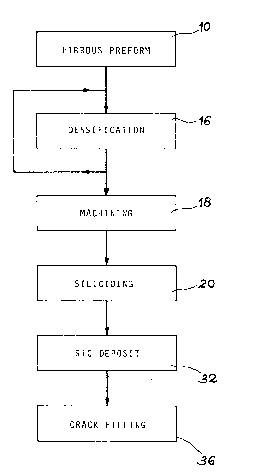
Fig. 1 diagrammatically different stages of the production of a
composite material part according to the invention.
Fig. 2 the orientation of the layers of fibres of the preform accor-
ding to the process of the invention.
Figs. 3a to 3c the siliciding stage of the process according to
the invention.
Fig. 4 a composite material part protected against oxidation accor-
ding to the invention.
Fig. 5 the tectonic behaviour of the outer coating, when the part
is exposed to shear forces.
Fig. 6 the influence of an orientation of the fibres not in accor-
dance with the invention on the orientation of the cracks and the
disorganization of the blocks obtained.
For simplification purposes, the following description refers to
the siliciding of two surface fibre layers. Moreover, this silici-
ding relates to the entire outer surface of the fibrous preform
or blank and in particular the upper surface and lower surface of
the preform.
On referring to figs. 1 and 2, the first stage of the process accor-
ding to the invention consists of forming a fibrous preform 19 by
superimposing layers 1 to 4 and 1' to 4' of carbon fibres 12. The
preform 19 fixes the final shape of the composite material part
and the number of superimposed layers is a function of its specific
use. This stage is represented by frame 10 in fig. 1.
The fibres 12 of each layer are oriented (fig. 2) parallel to one
another and are contiguous. They are generally in the form of bund-
les of 3000, 60~0 or 1200 filaments, which are parallel to one another.
SP 65 34.69 LC
7 ~ ~
-- 10 --
In fig. 2, the fibres 12 (or more precisely the fibre bundles) of
the outer layer 1 of the upper surface of th preform 19 are oriented
perpendicular to the fibres 12 of the underlying layer 2 and then
parallel to the fibres 12 of the layer 3 underlying the layer 2.
In the same way, the fibres 12 of the outer layer 1' of the lower
surface of the preform are oriented perpendicular to those of the
fibres of the underlying layer 2' and parallel to those of the fibres
of the layer 3'.
This 90 intersecting orientation of the fibres of the outermost
10 layers of the preform makes it possible to obtain an organized net-
work of cracks in the outer coating, as will be shown hereinafter
relative to figs. 3a to 3c.
It is possible to envisage arrangements other than that shown of
the outer layers of the fibrous preform to be silicided. In parti-
cular, the following orientations can be used (0/90/0/...) or
(90/0/0/...) or (0/0/90/...) or (0/0/0/...).
In fig. 2, the superimposing of layers of fibres corresponds to
a type 3D evo architecture, but obviously the invention has a much
more general application, as has been shown hereinbefore.
In particular, the process according to the invention applies to
the 2.5D architectures described in FR-A-2 610 951.
In fig. 2, the fibres of layers 4 and 4' in contact with the layers
respectively 3 and 3' are oriented at 45 relative to the fibres
of the layers 3 and 3' respectively.
For example, a planar, quasi-isotropic 3D evo part according to
the invention can have the following stack of layers:
(0/90/0/45/-45/90/0/45/45/90)sym .
SP 6534.69 LC
2~337~2
-- 11 --
In the above sym indicates that the stack is symmetrical relative
to the centre of the part and the figures represent the orientation
of the fibres relative to a reference direction. The figures 0
and 90 respectively indicate a parallel orientation perpendicular
to the reference direction and 45 and -45 respectively indicate
an orientation at 45 and at -45 relative to said reference direc-
tion.
This stack leads to an isotropy of the mechanical properties in
the plane, the layers of fibres working in accordance with four
directions at 45 from one another. An architecture with four direc-
tions close to 45 from one another at any point in the structure
e.g. makes it possible to form a component of a space shuttle nose.
Following the superimposing of the different layers of fibres accor-
ding to the invention, a piercing 14 is carried out on the different
layers to ensure their assembly. This piercing 14 is carried out
with carbon fibres and constitutes the third orientation of the
fibres in space. Further details of this procedure are given in
FR-A-2 612 950.
The following stage of the process relates to the densification
of the fibrous preform as indicated at 16 in fig. 1. This densifi-
cation consists of filling the spaces between the fibres 12 snd
thus form a carbon matri~ optionally doped with 2 to 10% by weight
SiC. It consists of several impregnation cycles of a carbon pre-
cursor and optionally SiC precursor, polymerization, pyrolysis and
heat treatment. The precursor of the carbon can be a phenolic resin
of the resol type or a furan resin. The doping by SiC can be carried
out by grafting siliconefunctions on the phenolic resin.
Polymerization is carried out at atmospheric pressure up to 200C
and is followed by crust removal in order to take off the excess
resin. Pyrolysis is performed in a neutral medium at approximately
SP 6534.69 LC
~ ~ r ~ r~ 4~ 2
- 12 -
800C in order to transform the crosslinked polymer into hard coke.
The heat treatment is performed at between 1200 and 1800C.
The number of successive cycles of these operations is generally
5.
Following densification, a machining, designated 18 in fig. 1 is
carried out and this more particularly applies to the edges and
holes used for the assembly of the finished mechanical part with
other parts in order to produce the space craft.
The following stage of the process, designated 20 in fig. 1, relates
to the s~liciding of the densified preform 19 with a view to forming
the outer anti-oxidation protection coating. This stage is illustr-
ated in greater detail in figs. 3a to 3c.
Siliciding consists of immersing (figs. 3a and 3b) the densified
prefcrm 19 in a mixture of powders 22 containing, by weight, 10~
A1203, 30% Si and 60~ SiC. These powders have a grain size between
30 and 60 ~m anl an apparent density after compression or tamping
of 1000 Kg/m3. Siliciding takes place in a graphite container.
This loaded container then undergoes a heat treatment at 1700C
in an argon atmosphere.
In this way the outer SiC coating 24 is formed over the entire outer
surface of the densified preform 19. The siliciding time is a func~
tion of the sought thickness for the coating 24. After removing
the siliciding powder the part is cleaned and the structure obtained
is that shown in fig. 3c.
If e represents the thickness of the coating 24 and E the total
thickness of the silicided part, 2e/E ~1/3 must be obtained to ensure
that the final part has a good mechanical behaviour, which is due
to the fibres 12 and to the carbon-containing matri~ 26.
SP 6534.69 LC
7 ~ 2
- 13
For example, it is possible to silicide a densified fibrous preform
of the carbon-carbon type with a total thickness of 4 mm, with a
thickness of 0.4 mm on each side, each layer of fibres having a
ehickness of 0.2 mm.
Siliciding is a thermochemical reaction locally transforming the
carbon of the fibres and that of the matrix into silicon carbide
as from the outer surfaces of the part and namely up to an optimized
thickness with respect to the diffusion of oxidizing gases. The
chemical reactions involved were indicated hereinbefore.
On cooling, the expansion incompatibility between the carbon of
the fibres and the matrix and the silicon carbide of the outer coat-
ing 24 creates cracks 28 traversing the silicided layer 24 (fig.
4) parallel to its thickness (axis z) and slightly penetrating the
carbon-containing matrix 26. These cracks issue to the outside.
The cracking of the outer coating, shown in figs. 3c, 4 to 6 is
that which is obtained at ambient temperature (20 to 25C).
As a result of the orientation of the fibres of the outer layers
1 and 2 of the preform in two perpendicular directions x and y,
the cracks 28 are oriented in accordance with these two directions.
Thus, parallelepipedic SiC blocks 30 are obtained and in this part~
icular case are shaped like a square in the plane ~y and of side
L. These blocks are independent of one another and adhere perfectly
to the carbon-containing matrix 26.
According to the invention, the cracks 28 of the silicided layer
24 retain the memory of the orientation of the ex-fibres 12 of carbon
transformed into SiC. Thus, the SiC layer is regularly broken up
in the direction of the carbon ex-fibres during the cooling of the
siliciding treatment with a millimetric spacing 1.
With the aid of an optical microscope, it is possible to see the
SP 6534.59 LC
2 ~ 2
- 14 -
orientation of the fibres at the origin of the network of cracks.
The greater the depth siliciding, the more open the cracks 28 and
the larger the upper surface of the blocks. The surface L2 of the
blocks is dependent on the relative thicknesses of the carbon portion
26 and the thickness e of the silicided layers, as well as the intri-
nsic properties of the material, such as the expansion coefficients,
its modulus and thermochemical contributions.
In summarizing, the width l of the cracks and the width L of the
blocks increase in accordance with a monotonic function with the
siliciding thickness e, everything else being equal.
Moreover, at ambient temperature 1 is dependent on the production
temperature of the silicide layer 24 and in particular on the temp-
erature difference between the maximum production temperature and
ambient temperature.
The cracks of the SiC layer close again when the temperature rises
and the blocks become contiguous for a temperature equal to that
of carbide production.
In particular, these cracks tend to reclose during the use of the
parts at high temperature. For a production at 1700C of the silic-
ided coating, a use of the mechanical part at 1700C leads to acomplete closure of the cracks. For example, for a production at
1700C 1 = 0~um at 1700C, 1=4~m at 1000C and l-lO~m at 20C.
Moreover, the expansion behaviour of the carbon fibres 12, which
is of an anisotropic nature, leads to a microcracking of the matrix
26. Thus, the expansion coefficient of a fibre in its length direc-
tion is low or even negative, whilst radially it is relatively high.
In additionj the precursor of the fragile carbon-containing matrix
cannot always adapt with respect to said anisotropy and become asso-
ciated with the volume change resulting from the heat treatments
SP 6534.69 LC
2~7~2
- 15 -
of the densification.
The microcracks of the matrix differ as a function of the position
of the matri~ in the composite material part and the reciprocal
orientations of the fibres. Moreover, the heat treatments for produ-
cing the matri~ and the possible coating of the carbon fibres byan appropriate material, referred to as si~ing, makes it possible
to obtain a very strong carbon-carbon composite material. This
results from the fibre/matrix bonds which, for high stresses, will
permit rectilinear or angular microdisplacements and gradually the
transfer of char~es to adjacent fibres by successiYe breaking oper-
ations of said bonds.
The coating of the fibres by the sizing product is carried out during
the production of the layers of fibres or on the actual fibres prior
to weaving.
The sizin~ products and the coating methods usable in the invention
are those of the prior art.
During the use of the mechanical part, the cracks of the outer coat-
ing lead to a preferred penetration of the o~ygen into the carbon-
containing matrix 26 and it is also necessary to fill them.
The first stage of the healing of the cr~cks indics~ed at 32 in
fig. 1 consists of depositing a SiC layer 34 ~fig. 4) by CPVD.
To this end, the part is placed in an isothermal furnace or oven
kept at approximately 1000C and in which circulates a mi~ture-of
chlorosilane (CH3)nSiC1(4 n) with 0 ~ n ~ 4, associated with a hydro-
carbon and in particular an alkane (methane, ethane, propane) and/orhydrogen. For example, Jse is made of a mixture of trichloromethyl
silane and hydrogen in a (H2)/(CH3SiC13) ratio of 4 to 12.
This stage lasts appro~imately twice two hours, namely two hours
SP 6534.69 LC
2~3~37l~2
- 16 -
for the upper face of the part and two further hours for the lower
face.
This SiC deposit 34 shown in fig. 4 makes it possible to reduce
the width 1 of the cracks 28, but without closing them. Thus, as
the SiC deposit 34 takes place at high temperature, their spacir~g
is already reduced compared with that at ambient temperature, which
does not permit a penetration of the SiC to the bottom of the cracks.
This reduction of the opening of the cracks largely limits the oxygen
penetration into the carbon-containing matrix during the use of
the part.
This is followed by a second crack filling stage 36. As shown in
fig. 4, this healing process can consist of a deposit of an aluminium
nitride coating 38 over the entire outer (lower or upper) surface
of the part, followed by a deposition of aD alumina coating 40.
The aluminium nitride coating serves as a reaction barrier between
the SiC 34 and the alumina 40. The AlN coating can be produced
with a mixture of aluminium chloride, hydrogen and ammonia, accompan-
ied by neutral gas (in particular argon~ scavenging. This AlN coat-
ing is deposited by CPVD at approximately 950C. The average thick-
ness of the coating is approximately 1.5 ~m.
The alumina coating 40 is deposited by CPVD at approximately 950C
with a mixture of AlC13, H20 and C02. The coating 40 has a thickness
of approximately 5 ~m.
It is possible to replace the aluminium nitride coating by a hafnium
nitride coating.
The part obtained in this way can be used under particularly severe
ambient conditions and in particular for forming the nose of space-
craft exposed to temperatures of approximately 1800C on reentering
the atmosphere.
SP 65~4.69 LC
2 ~ 2
For other uses, it is possible to replace the AlN and alumina coat-
ings respectively by a silica coating and a borosilicate glass coat-
ing, as described in FR-A-2 611 198.
With this type of protection, the part obtained can be used for
forming the leading edges of a space shuttle.
As shown in fig. 4, the siliciding of the carbon-carbon material
not only leads to the formation of SiC blocks 24, but also to the
formation of an underlayer 42 of carbon and SiC ensuring a good
adhesion of the coating 24 to the carbon-carbon material.
A study of the mechanical behaviour of the anti-oxidation protection
(AOP) obtained in this way (SiC layer, plus healing of the cracks)
reveals a tectonic mechanical behaviour.
From the mechanical standpoint, the relatively ~hick siliciding
SiC layer (a few tenths of a millimetre) compared with the healing
thickness imposes itself, whilst all the different healing deposits
occurs on a moving bed of blocks. The mechanical participation
of this healing is of a secondary nature in view of its limited
thickness (~10 ~m).
As the main directions of the network of cracks are orthogonal, the
equivalent material of the anti-oxidation protection is naturally
considered to be orthotropic. The orthotropic a~es of the AOP coin-
cide with those of the underlying carbon-carbon material.
The tectonic description of the AOP in accordance with its ortho-
tropic axes will now be given.
Compression.
The mechanical compression forces transmitted to the AOP tend to
reclose the cracks and the blocks progressively move against one
SP 6534.69 LC
~3~
- 18 -
another. This progressive stack resembles a spring located between
two blocks. The equivalent compression modulus of the AOP is aver-
age, because it is dependent on the high modulus of the SiC block
and the limited stiffness of the inter-block "spring".
When the forces increase, the cohesion of the blocks, close to the
two silicided surfaces, improves the stability of the SiC/C-C/SiC
sandwich. The equivalent compression breaking stress of the AOP
is high.
For limited thickness unoxidizable carbon-carbon materials, the
AOP increases considerably the compression characteristics of the
sandwich.
Tension
The blocks tend to open and it is no longer possible to count on
the modulus of the SiC block. A tension in a main direction is
combined with a transverse compression by the Poisson effect and
a limited participation of the spring can be envisaged. By an inter-
laminar shear entrainment flux of the AOP towards the carbon-carbon,
it is possible for the local rigidity of the latter beneath a block
to be increased, thus slightly increasing the overall rigidity.
In practice, the mechanical participation of the AOP is negligible
in tension.
Planar shear
The participation of the AOP is intermediate between the two extremes
constituted by tension and compression. Fig. 5 shows the blocks,
which are auto-blocking by rotation and are supported against one
another.
Therefore the shear stress and modulus of the AOP must be taken
into account, because they improve the characteristics of the limited
SP 6534.69 LC
~3~2
- 19 -
thickness, unoxidizable carbon-carbon sandwich.
If instead of orienting the fibres of the outermost layers in accor-
dance with two perpendicular directions (fig. 2), as shown in fig.
6, the fibres 12 of the upper layer la and those of the underlying
layer 2a had been oriented in two directions forming an angle of
45, there would have been a corresponding damage to the outer coat-
ing 24a during a random mechanical stressing of the protected part.
Thus, this 45 surface orientation of the fibres leads to the forma-
tion of two types of blocks 30a and 30b, one type per layer of fib-
res, and to cracks between the blocks which are totally displacedbetween the individual layers. The mechanical stressing then causes
a delamination of the upper layer la of silicided fibres entraining
with it the healing layers of the cracks.
The loss of most of the AOP leads to a significant oxidation of
the carbon-containing part during its use at high temperature.
The microcracks of the carbon matrix and the organized cracks of
the SiC layer of the AOP are fundamental elements for a very good
mechanical behaviour in the presence of heat of the composite mater-
ial parts. With respect to carbon-containing composite materials,
these microcracks and cracks in well controlled form indicate their
non-fragile behaviour. The understanding of the mechanical behaviour
of the carbon-carbon part and the tectonics of its AOP have made
it possible, according to the invention, to contribute to the improv-
ement of composite material parts and in particular their resistance
to oxidation.
SP 6534.69 LC