Note: Descriptions are shown in the official language in which they were submitted.
WO90/13419PCT/GB90/00691
;~:05387;0
. .
LAND VEHICLE SUSPENSION CONTROL SYSTEM
This invention relates to a land vehicle
suspension control system.
By "land vehicle" is meant a vehicle adapted
for motion over the land in contact therewith,
examples being motor cars, motor cycles, tractors and
tracked vehicles.
In particular, the invention relates to a land
vehicle suspension control system for a land vehicle
having an active suspension system.
An active suspension system is a suspension
system in which conventional suspension components,
such as springs and dampers, are assisted or replaced
by actuators operable, for example in response to
command signals from a microprocessor, to correct,
change or control the attitude of the vehicle. An
aim of such acti~e suspension systems is to minimise
variations in the forces experienced by the vehicle
body, thereby improving vehicle safety and enhancing
driver and passenger comfort.
The command signals which control the actuators
are generally derived from measured values of a
number o~ variables defining the vehicle's attitude.
In a truly active suspension system, there is the
capability of controlling the actuators to respond to
measured road inputs, that is due to perturbations in
the road surface, whilst the actuators can be
controlled not to extend and contract in response to
loads imposed on the vehicle suspension by virtue of
vehicle acceleration and cornering and loads carried
~090/13449 PCT/GB90/00691
~(~S3~7() ~ - 2 -
in the vehicle.
Active suspension systems are well known. For
example, EP-A-0114757 discloses an active suspension
system for a four wheeled motor vehicle in which
force measurements are taken at the points of support
of the vehicle body on each wheel/hub assembly and
processed to produce a demanded output of the
actuator secured to operate between the respective
wheel/hub assembly and the vehicle body.
The attitude of the vehicle can then be
- controlled by converting the forces measured at the -- -
points of support to a set of modal forces (e.g.
heave, pitch, roll and warp forces), from which the
actuator outputs required to overcome the combined
modal forces in order to maintain the desired
attitude of the vehicle are then calculated.
A significant advantage of such an active
suspension system is that the suspension
characteristicslof the vehicle can be continuously
altered to accomodate varying road conditions and/or
operating conditions of the vehicle. This facility
permits the construction of a vehicle which has
improved safety charateristics, since it is possible
to maintain a greater degree of contact of the
vehicle wheels with the land, and the behaviour of
the vehicle is likely to be more predictable to the
driver, than in the case of a vehicle not having an
active suspension system.
Known active suspension systems include means
for manipulationg the values of the modal forces to
produce a demanded output of actuator means arranged
to oppose the modal forces, thereby maintaining a
: . ~
W~90/134~9 ~ PCT/GB90/00691
;2CS38~70
- 3 -
constant force on the vehicle body.
However, previous control systems used in
conjunction with active suspension systems have
operated on the principle of produ~ing a demanded
pcsition of the actuator means and operating the
actuator means accordingly. The actuator means
generally includes a hydraulic actuator operating
between each wheel/hub assembly and the body the of
vehicle.
,, The frequ,ency response of an electro-hydraulic
actuator can be improved dramatically if the control
processor can be arranged to output a velocity,
rather than displacement demand. When this is the
case the primary input to the actuator is a velocity
demand.
According to the invention there is provided a
land vehicie suspension control sytem comprising
means for measuring forces acting between the
sprung mass of said vehicle and unsprung masses as
connected thereto;
means for producing signals proportional to the
resulting measured force values;
means for determining from said signals the
values of the forces required to be applied between
siad unsprung masses and the sprung mass to minimise
force changes experienced by said sprung mass;
means for determining the values of demanded
relative velocities required between the sprung mass
and said unsprung masses to satisfy said force
requirements; and
means for applying said required forces between
said unsprung masses and the sprung mass of the
vehicle in proportion to said values of said relative
.: .
: '
. ~ '
'
W090/l3449 PCT/GB90/00691
.,
205387()
velocities required between the sprung mass and s~id
unsprung mass.
It is advantageous, in accordance with accepted
theory relating to control systems, to have some form
of feedback measurement of the relative velocity
between the sprung mass and each unsprung mass
respectively.
However, in the field of motor vehicles, it is
necessary to minimise the size, weight and complexity
of components, and it is further a requirement that
the feedback measurements are accurately and rapidly
obtained.
Therefore, the control system of the invention
preferably includes means for measuring an output
characteristic of said means applying said required
forces, the measured value of said output
characteristic being compared in comparator means
with a corresponding required value of said output
characteristic to produce an error value of said
characteristic in response to which said control
system operates, said output characteristic being
measured and compared as a position characteristic.
Preferably the control system includes means
for synthesising the relative velocity value required
between the sprung mass and each unsprung mass.
Preferably, the control system includes, means
for synthesising, from the relative velocity value
re~uired between the sprung mass and each unsprung
mass of the vehicle, a relative position value
required between the sprung mass and each unsprung
mass of the vehicle.
- ~ . '
" '' ' ':,, :
w090~13~9 . ' PCT/GB90/00691
_ 5 - ~ ~538~Q.~
A demanded position value may advantageously be
included to ensure conformity of the physical output
of the system with the theoretical output availab].e.
Preferably said synthesised relative position
value is compared in said comparator means with said
measured position characteristic of said means for
applying said required forces.
Preferably said means for synthesising the
relative velocity value required between.the sprung
mass and each unsprung mass conditions said relative
velocity value as a modal velocity of said sprung
mass, the mode corresponding to one of the heave,
pitch, roll and warp modes of sprung mass
displacement.
The invention will now be described by way of
example with reference to the drawings, in which:
Figure 1 is a schematic representation of the
effects of heave forces on a motor vehicle body;
Figure 2 is a schematic representation of the
effects of pitch forces on a motor vehicle body;
Figure 3 is a schematic representation of the
effects of roll forces on motor vehicle body;
Figure 4 is schematic representation of the
effects of warp forces on a motor vehicle body;
Figure 5 is a schematic block diagram
representation of a portion of a known control system;
Figure 6 is a graphical representation of the
output characteristics of the control system of
Figure 5;
Figure 7 is a schematic biock diagram
representation of a control system in accordance with
the invention;
WO90/13449 PCT/GB90/00691
'` `'1, ~f ~
2C~ 6 -
Figure 8 is a schematic representation of a
portion of a control system according to the
invention.
Referring to the drawings, Figures 1 to 4 show
schematically a vehicle comprising a sprung mass in
the form of a motor vehicle body 20 and four unsprung
masses, i.e. four wheels lO, 11, 12, 13 and an
interconnecting suspension system (not shown) for the
wheels. The vehicle body 20 includes the engine,
transmission and all the anciliary components of the
motor vehicle.
Figures 1 to 4 are schematic representations of
the typical displacements of the vehicle body 20
occasioned by heave, pitch, roll and warp forces
respectively. In Figures 1 to 4 the front left hand
wheel of the vehicle is referenced 10, the front
right hand wheel is referenced 11, the rear left hand
wheel is referenced 12, and the rear right hand wheel
is referenced 13. The heavel pitch, roll and warp
forces are respectiv~ly indicated by arrows H, P, R '
and W. The modal forces shown in Figures 1 to 4 are
indicated acting positively according the si~n
convention adopted. The front of the vehicle is
indicated generally by the reference 21, and the rear
by reference 22.
In Figure 1 the modal force of heave is an
equal downward force acting on the four points of
support of the vehicle body 20 on the wheels 11, 12,
13 and 14, and thus the vehicle body tends to move
uniformly downwardly without tilting in any direction
under the influence of positive heave.
Positive pitch modal forces are illustrated in
- . . ,
-; , ' . ~
: . :
WO90/13449 PCT/GB90/00691
- 7 - ~.O ~
Figure 2 where it is shown that a positive pitch
modal force applied to the vehicle body 20 tends to
result in downward displacement of the front end 21
of the body with no tilting from side to side, and
S with the rear 22 of the vehicle being displaced
upwardly from its original position.
The positive roll modal force is shown in
Figure 3 as tending to produce a tilting displace~ent
of the vehicle body about its longitudinal axis, with
downward displacement of the left hand side of the
vehicle body 20 and upward displacement of the right .
hand side.
lSFigure 4 shows the effect of a positive warp
force on the vehicle body 20. A warp force tends to
displace one pair of diagonally opposite corners of
the vehicle body 20 downwardly and the other pair
upwardly in the case of a generally rectangular body.
According to the sign convention used herein,
the front left and rear right corners of the vehicle
are downwardly displaced for positive values or warp
forces.
Clearly the magnitude of a displacement caused
by warping is small, due to the torsional rigidity of
the vehicle body itself. The other three modal body
forces described above, may depending on the
stiffness of the suspension between the body and the
wheel/hub assemblies, produce large deflections of
the body from its initial position~
The true warp force may not, therefore,
necessarily be simply the combined application of
pitch and roll forces, and is analysed in its own
WO90/13449 PCT/GB90/00691
`~ o 5~ 8 -
right during operation of a control system in
accordance with the invention.
Referring now to Figure 5 there is shown as
schematic block diagram representation of a portion
of a known land vehicle suspension control cystem for
controlling the attitude of the vehicle.
In Figure 5 there is shown as hydraulic
actuator llO secured, for example, to operate between
the sprung mass and an unsprung mass of a vehicle.
The sprung mass of the vehicle is formed as the
vehicle body (now shown) and the unsprung mass may be
a wheel/hub assembly (now shown). ,
The actuator has a rod 111 to which is secured
the vehicle body, the wheel/hub assembly being
secured on the housing 112 of the actuator.
The actuator 110 operates in response to
movements of a solenoid valve 113 controlling the
distribution of hydraulic fluid in hydraulic supply
lines 114 and 115, which fluid is arranged to act on
the piston of the actuator llO.
The actuator 110 is preferably a
double-actuating electro-hydraulic actuator,
comprising a sealed cylinder and a piston attached to
a connecting rod. The sealed cylinder is capable of
containing high pressure fluid without significant
leakage. The piston is attached to the connecting
rod and is housed within the cylinder. The piston
divdes the cylinder in to two cha~bers. The piston
is fitted with seals to prevent significant leakage
of the fluid from one chamber to another.
,
'
WO90/13~9 PCT/GB90/00691
_ g _
The solenoid valve 113 is preferably a four
port flow control valve, or electro-hydraulic servo
valve (EHSV). The solenoid valve 113 preferably has
two input and two output ports. One port is
connected to a source of high pressure hydraulic
fluid, the other input port is connected to a return
path which is held at low pressure. The EHSV is
designed such that when an electrical current is
passed through its energising coil, hydraulic fluid
is allowed to flow from the high pressure source to a
chamber on onP side of the piston contained in the
actuator 110, whilst hydraulic fluid is allowed to
flow from the other chamber, on the other side of the
piston, to the return path. This causes the piston
lS to move relative to the cylinder with a velocity
proportional to the electric current applied to the
energising coil and the load reacted by the
differential pressure across the piston. When the
polarity of the current is reversed the velocity of
the piston is reversed. If the EHSV conforms to the
ideal, then the velocity of the piston will be zero
when the electrical current applied to the energising
coil is zero.
2S Solenoid valve 113 operates under the command
of an electrical signal carried by line 116, which is
the output of a control system, indicated generally
by the reference numeral 120.
The actuator is designed under the assumption
that the pressure of the fluid source is constant and
sufficiently high that any pressure drop across the
piston can be neglected. When this is the case, then
the velocity of the piston relative to the cylinder
is proportional to the current passed through the
energising coil. The constant of proportionality i5
.' .
WO90/13~19 PCT/GB90/00691
, ,.V5387~.
kown as the actuator "gain". Its value depends on
the actuator cross-sectional area, the maximum flow
capacity of the EHSV and the fluid supplied
pressure. Mathematically, the relationship can be
stated as follows;
DX=gh x iservo
where DX is the actuator velocity
iServo is the current passed through the
energising coil
gh is the actuator gain.
..
It is normal to connect the energising coil of
an EHSV to a current amplifier, such that the
actuator velocity is proportional to the voltage
applied to the current amplifier. When the gain of
the current amplifier is unity (a unit volatage
generating a unit current), then the relationship
between the voltage applied to the amplifier and the
actuator velocity may be written as follows:
DX = gh x Vdem
where vdem s the voltage applied to the
current amplifier.
It should be noted that electro-hydraulic
actuators are not perfect transducers. Offsets can
occur within an EHSV and within a current amplifier
used to provide iServo. This means that a zero
voltage input to the current amplifier may result in
a non-zero velocity of the piston.
It should also be noted that compliance of the
fluid contained within the cylinder will also effect
, . .
:
WO90/l3~49 PCT/GB90/00691
2QSa870
actuator performance at high frequency. Further, in
an active suspension system the pressurised hydraulic
fluid is provided by a pump operating from engine
output. Therefore, a significant change in engine
speed can cause substantial fluctuations in hydraulic
supply pressure. Also, since in automobile
applications it is required that power consumption is
minimised, generally an undersized actuator is
adopted, resulting in substantial variations in
pressure differential across the piston and a
consequent variation in actuator performance. The
control system for an actuator must be designed to
maintain a satisfactory actuator performance under
all, or at least most, conditions.
In Figure 5 the control processor of the active
suspension system outputs an actuator position
command Xdem. It is therefore necessary to provide
an additional circuit whose function it is to convert
the actuator position command into an actuator
velocity demand. The simplest and most common
technique for effecting this processing is to
construct a "displacment error loop". Such a system
is shown in Figure 5, with a slight improvement on
the basic system being the inclusion of a "shaping
filter". The shaping filter is commonly a "lead/lag"
filter.
Control system 120 represents the output stage
of a larger control system, which produces as its
output a demanded position Xdem of the actuator 110.
The Xdem signal is carried by line 121 and is
summed in summing junction 122 with the negative
value of the measured actuator position Xact carried
by line 123. Xact is measured by transducer means,
such as a Linear Variable Differential Transducer
W090/l3~9 PCT/~B90/00691
.~9~38~ - 12 -
LVDT, associated with actuator llO to produce an
electrical signal related to the position of rod 111
relative to actuator housing 112.
The transfer function of the displacement error
loop of Figure S can be written:
1 + S T1
[1 + S/(Gh-Gn)].[1 + sT2]
Typically the time constant Tl will be greater
than the value of T2 and will be set so that:
. -
T1 = 1/(Gh.Gn)
When this equality has been achieved, the
transfer function of actuator motion will revert to
single pole low pass filter. The system has an
advantage over a system without a "shaping filter" in
that the break frequency of the Displacement Error
Loop can be increased by setting the value of T2,
typically the break frequency is increased by a
factor of 3 by including the "shaping filter". The
logarithm of the gain of the system is plotted
against the logarithm of the frequency of the system
in Figure 6. The figure also shows the frequency
response of a displacement error loop without a
"shaping filter" and the frequency response of the
lead/lag network of the "shaping filter".
It can be seen from the graph that response of
system is limited by the necessity ~or including a
Displacement Error Control Loop to convert the
position control signal Xdem in to a velocity
control system. Whilst the break frequency can be
increased by increasing the gain of the system said
~090/13449 PCT/GB90/00691
0S3870
., " ~ i ;"
increases are limited by problems of instability.
The frequency response of the electro-hydraulic
actuator llo can be dramatically improved if the
control processor is arranged to output a velocity
rather than a displacement demand. When this is the
case, the primary input to the current amplifier is
the velocity deman~ and the performance of the
actuator is therefore not limited by the need for a
displacement error control loop.
It is necessary to maintain the position of the
actuator accurately. Hence, anciliary control loops
must be added to the control system when a velocity
demand signal is produced by the system controller.
For example, it is necessary to generate from the
velocity demand signal an estimate of the required
actuator position, this being compared with the
actual displacement of the actuator in a low gain
displacement error loop. Also, it is necessary to
counter the bias of the actuator and its current
amplifier so that a zero velocity demand yields a
zero actuator velocity.
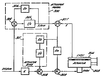
A schematic diagram of a control system
according to the invention is shown in Figure 7.
This contains a forward velocity demand loop, an
actuator "model" 300 and a slow bias estimator 301.
The input to the system is a demanded velocity
DXdem. This signal is input into the actuator
model 300. The actuator model integrates the signal,
as shown as 305, to give a position signal Xdem.
The position frequence signal is fed back through a
low gain position feed back loop 306 to the junction
302. The feed back loop is necessary to force the
,
WO90/13~49 PCT/G890/00691
~0~;3870
average value of the integral to zero. Since the
integral represents the modelled displacement of the
actuator, over a period of time the displacement
should average out to zero and hence it is necessary
to ensure that the actuator model biases the
displacement of the actuator towards zero.
The velocity demand loop of the invention feeds
in to the velocity demand signal two signals at
lo junctions 308 and 309. The first of these is a
signal proportional to the difference between the
actual actuator displacement X and the modelled -
actuator displacement Xdem. This signal is added
to the DXdem signal at 309 and adjusts the velocity
demanded of the actuator to compensate for any
differences between the modelled displacement and the
actual displacement.
.
The actuator bias estimator 301 integrates the
displacement error to generate an estimate of the
actuator offset. The offset signal is added at 308.
This signal acts to compensate for the bias of the
actuator.
The values of the parameters kv and kb are
chosen to be sufficiently small so as not to intefere
perceptibly with the operation of the actuator and
'its control loops. Again the gain of forward
velocity loop is denoted by k and is chosen as a
suitable value when considering a particular system.
The invention has a major advantage over the
prior art in that its frequency response is limited
~- in no way by the need for a displacement error loop.
The only limits imposed upon the frequency response
of the velocity demand loop disclosed above are
W O 90/134~9 PC~r/GB90/00691
- 15 - ~OS3~3~70
,,. ;.j,,~ ;,, ;.
.~ r~,~t,~
practical limits, imposed by digital filters within
the active suspension control system, the frequency
response of the valve and also the sampling rate of
the controlling active suspension system.
The controlling equation for a velocity demand
control loop, according to the invention, omitting
the bias estimation and the actuator model position
feed back loops, is as follows;
DX = K.DXdem + Gn [Xdem = X]
.. . . . .
where, DX is the actuator velocity
DXdem is the demanded velocity
Xdem is an estimate of demanded position
X is the "forward" loop gain
Gn is the displacement error loop gain.
The transfer function of the arrangement can be
written:
Gn + s.K
Gn + s
Clearly, with K set to unity (i.e. the forward
loop gain adjusted so that the performance of the
model is matched to that of the actutor~ the transfer
function collapses to unity.
Referring now to Figure 8, there is shown a
schematic representation of a vehicle active
suspension control system.
The arrangement of Figure 8 represents one
quarter of the control system of a four-wheeled
vehicle, one unsprung mass in the form of a wheel/hub
.
: .. :...... :.
~ ' :'`' . .
Wo 90/13449 pcr/GB9o/oo691
16
Z~ 5 3 87
assembly being shown, the system for the remaining
three unsprung masses being similar.
In Figure 8, the sprung mass of the vehicle in
5 the form of the vehicle body 220 is shown supported
on a number of suspension components indicated
generally by the reference sign 130, which are in
turn supported on a wheel and tyre modelled as an
unsprung mass 40 supported on a spring 41 and a
lo damper 42 representing the tyre characteristics.
The suspension components 130 comprise a --
vertically aligned hydraulic actuator 131 secured at
its upper end to a load cell 132 which is separated
from the vehicle body 220 by an isolator 133, which
may be, for example, a rubber block.
A spring 134 is shown connected in parallel
with the hydraulic actuator 131. In a vehicle where
20 the active suspension components assist the
conventional suspension components, the spring 134
represents the road spring of the vehicle. Where the
active suspension components replace the conventional
components of the vehicle suspension system, the
25 spring 134 can be taken to model the spring stiffness
of the active suspension components.
The input and output ports of the hydraulic
actuator 131 are connected via hydraulic pipe~ork
30 131a and 131b to a hydraulic control circuit 50
including a suitable supply pump 51. The hydraulic
circuit 50 operates, via electrical connection 50',
under the command of a microprocessor 60 which
produces a demanded output of the actuator 131 in
35 response to a number of measured inputs.
,~
~ . . ,
- : '
::
WO90/l3449 PCT/GB90/00691
;~C~;3870
The inputs to the microprocessor 60 are as
~ollows:
Line 61' carries the output of accelerometer 61
measuring the vertical acceleration of the unsprung
mass 40;
Line 62' carries the output of linear variable
displacement transformer (LVDT) 62 measuring the
displacement of actuator 131;
Line 63' carries the output of load cell 3~
measuring the force transmitted to sprung mass 20 via
the suspension components 130:
- Line 64' carries the output of accelerometer 64
located near the sprung mass centre of gravity and
measuring the sprung mass longitudinal acceleration;
Line 65' carries the output of acceleromet~r 65
located near the sprung mass centre of gravity and
measuring the sprung mass lateral acceleration;
Line 66' carries the output of gyroscope 66
located near the sprung mass centre of gravity and
measuring the sprung mass yaw rate (i.e. rotational
acceleration~;
~ ine 67' carries a vehicle speed signal from
measuring means (not shown);
Line 68' carries a steering rack displacement
signal from measuring means (now shown);
Line 69' carries a hydraulic system pressure
signal from measuring means (now shown); and
Line 70' carries a swash plate angle signal
from measuring means (now shown) located in the pump
51.
The active suspension system described above
. comprises two prinicple elements, one element
`~ synthesises an enhanced suspension to react to road
inputs, the other element controls the average
position of the unsprung masses relative to the
`'
~ '
., .
WO90/13~9 PCT/GB90/00691
- 18 -
ZC53870
sprung mass. In principle, the two elements can be
considered as defining the requirements for two
separate sets of actuators, the X sets being arranged
to act in series. When considering a vehicle as a
whole, the control system considers eight logical
actuators, but controls four physical actuators. The
element of the control system dealing with road
inputs synthesises four "modal" spring and damper
units reacting to the road inputs. A velocity demand
is then output from the controller, demanding a
velocity from the actuator to react to the road
inputs.
....
To deal with steady state inputs from driving
conditions such as cornering, bra~ing and
accelerating, the control system also considers
theoretically a set of actuators, each of which acts
in series with one of the actuators reacting to road
inputs. In practice, both the signal controlling the
actuators in response to loads imposed on the vehicle
by the road and the signals controlling the actuators
in response to steady state loads arriving from
aerodynamic forces, cornering, etc., are both input
to the same actuators, even though the system
considers the actuator as being two separate
actuators acting in series. The control system acts
to alter the average actuator position in response to
the steady state input, so that the suspension system
does not deflect in response to such inputs.
The active suspension control system mentioned
above has two velocity outputs DXd and DXs. DXd is
the velocity demand output to the actuators in
response to road impulses. DXs is the velocity
demand output to the actuator in response to steady
state loads on the vehicle. Therefoxe the total
w09n/l3449 PCT/GB90/00691
Z0~3~ s i
velocity demand output to an actuator is a sum of two
components as follows;
DXo = DXd + DXs
As described before the velocity demand loop of
the invention models actuator displacement. In the
active suspension system employed by the applicant
the total model displacement is in fact the sum of
two model displacements, Xd and Xs. Xd is the model
displacement of the actuator in response to road
inputs. Xs is the modelled actuator displacement in
response to steady state inputs. The total model
displacement Xo is the sum of two as follows:
Xo = Xd + Xs
In the active suspension system in fact each of
the four actuators used to control the fourth wheel
and hub assemblies are controlled individually, but
for purposes of simplicity, we shall only consiser
the control of one such actuator.
As mentioned before, in general an actuator and
2S its associated current amplifier will have small
offsets, so that a zero velocity demand will not
yield zero actuator velocity. An estimate of the
offset value can be obtained integrating the actuator
displacement error, that is to say the difference
between the demanded and actual displacement. The
estimates can then be included in the control system
to maintain more accurate control. In a preferred
embodiment of the invention, the offset value is
estimated by a recursive equation as follows;
Xb = Xb + Kb (Xo - Xr)
WO90/13449 PCT/GB9~00691
2C5~70 : ` - 20 -
"~
where Xb is the EHSV bias estimate
Kb is a scale or integration constant
Xr is the actual actuator displacement.
In a vehicle suspension system the performance
o~ an elctro-hydraulic actuator is also dependent
upon the fluid supply pressure. This can vary
substantially in a vehicle, to the extent that it is
necessary to introduce a further factor in to the
control of the actuators to reduce the variation in
performance of the actuators with changes in supply -
pressure. The factor PRfact adjusts the velocity
demand signal to account for the variations in the
supply pressure.
The PRfact factor and the offset factors are
combined into the velocity demand loop of the
invention described earlier. The current amplifier
input voltage, which results in the displacement of
the actuator is finally computed as being the
following;
P~fact. (Gf~DXo + Gd.(Xo - Xr) + Xb)
It can be seen from the equation that the
active suspension system used by the applicant
modifies the velocity demand to compensate for bias
errors and fluctuations in the hydraulic fluid supply
pressure.
The main advantage of the invention is that the
frequency response of the control system is vastly
improved over the position demand control systems of
the prior art. The invention overcomes the
difficulties of restricted band width response
PCI /GB90/00691
Z'C5~3870
t ~
imposed by the position control loops of the prior
art. In fact, the frequency response of the present
invention is only limited by practical
considerations, such as filtering necessary in the
active suspension control system, the frequency
response of the servo valve in actuator and also the
sampling rate of the active control systems.