Note: Descriptions are shown in the official language in which they were submitted.
;~C5~75f;
SPECIFICATION
DISCHARGE EXCITING EXCIMER LASER DEVICE
TECHNICAL FIELD
The present invention relates to a discharge-exciting
laser device compr-ising a pair of main discharge electrodes
and an auxiliary electrode.
BACKGROUND TECHNIQUE
The conventional technique of this kind is disclosed
in Japanese Patent Laid-Open publication No. 91982/1986.
This Japanese Patent Laid-Open publication NO. 91982
discloses a discharge exciting excimer laser device in
which for extending the life of laser gas, alumina ceramics
inert to laser gas is used in place of quartz heretofore
used to constitute a dielectric.
In the discharge exciting excimer laser device of
this kind, it is necessary for increasing a laser output
to activate preliminary ionization, when auxiliary discharge
takes place between a main discharge electrode and an
auxiliary discharge electrode, that is, photo ionization
effect caused by ultraviolet luminescence from the auxiliary
electrode and the supply of electron to a main discharge
space.
To this end, it was necessary (1) to quicken a rise
of voltage between the main discharge electrode and the
auxiliary discharge electrode, (2) to increase a dielectric
~5~756
constant of an dielectrlc, (3) to reduce the sectlonal
thickness of the dielectrlc, and (4) to improve a contact
between the dielectric and the electrode. In addition,
there was a technical problem of improving the insulating
performance between the electrodes.
However, in the conventional techniques including
the aforesaid publication, sufficient consideration has
not been paid to the aforesaid points. Particularly, the
shape of the dielectric in the aforesaid points (3) and
(4) has been ignored.
More particularly, in the prior art, the dielectric
to surround the auxiliary electrode was in the shape of
cylinder (a round pipe) or flat plate, and the inner surface
thereof in contact with the auxiliary electrode was curved,
there were difficulties in that polishing work is difficult,
and the operation for receiving the auxiliary electrode
therein is cumbersome.
When a high voltage of the order of 30 kv was applied
in order to obtain a high output, a dielectric breakdown
possibly occurs in the dielectric construction having the
aforementioned shape.
On the other hand, Japanese Patent Publication
No. 64069/1988 discloses a discharge exciting pulse laser in
which a dielectric in the form of a tube is used and a
cooling medium is sealed into the tubular dielectric. The
feature of this patent publication lies in that a dielectric
:,~
.
:: ;
' ~ ~
~C~75~i
is formed into a tubular configuration, into whlch Is sealed
a cooling medlum, and nothing is described of the fact
that a dielectric should be formed into a square pipe.
DISCLOSURE OF THE INVENTION
The present invention has employed the following
means to increase the laser output and improve the insulat-
ing performance.
The present invention provides a discharge exciting
excimer laser device comprising a pair of main discharge
electrodes with a laser optical axis being in a longitudinal
direction, said main discharge electrodes being arranged
opposedly to each other over said laser optical axis, a
dielectric arranged externally of said pair of main discharge
electrodes and opposedly to one of said main discharge
electrodes, and an auxiliary electrode opposed to said one of
main discharge electrodes through said dielectric, said
dielectric being formed into a cylindrical configuration and
whose side opposed to the main discharge electrodes is in the
form of a flat plate, said auxiliary electrode being embraced
within the dielectric ieaving a space and being opposed to
said one of main discharge electrodes with said flat plate
portion sandwiched therebetween.
According to the aforementioned means, said dielectric
is formed into a cylindrical configuration and the side
thereof opposed to the main discharge electrodes being in the
form of a flat plate, and said auxiliary electrode is
--3--
xc~'a755~
embraced within the dielectric leaving a space and opposed to
one of the main discharge electrodes with said flat plate
portion sandwiched therebetween. With this arrangement, the
insulating performance can be improved.
If at least one surface of said flat plate portion is
subjected to mirror surface polishing, the main discharge
electrode or the auxiliary electrode can be placed in close
contact with said surface. When the dielectric is configured
as described above and the flat plate portion is made thin,
the preliminary ionization electron density can be increased.
With respect to the extent of surface polishing, the
difference of altitude in unevenness of the surface is
100 ~ m or less, preferably,, 10 ~ m or less.
Furthermore, the dielectric is formed into a
cylindrical configuration, particularly, a square pipe
configuration comprising a flat plate portion whereby the
insulating performance can be improved, and the process for
receiving the auxiliary electrode can be simplified. In
addition, the dielectric is constituted by a rod-like member
having a n-shaped section with wall portions extended from
opposite sides of the flat plate portion toward one of the
flat portion in the square pipe and a flat plate-like cover
member for covering the open side of said n-shaped rod-like
member into a square pipe configuration. With this
arrangement, both surfaces of the n-shaped flat plate portion
in contact with the electrode can be polished to increase the
~ 2C5~755~
laser output. Moreover, the formation of the square pipe
becomes easy.
As the dielectrlcs used in the present invention,
there can be mentioned ceramics such as alumina ceramics, and
inorganic materials such as quartz glass, borosilicate glass
(for example, PYREX, the trade name, manufactured by
Dow Corning Corp.), strontium titanate etc.
BRIEF DESCRIPTION OF THE DRAWINGS
Figs. 1 to 4 show embodiments of the present invention.
Fig. 1 is a front sectional view showing an electrode portion
of a discharge exciting excimer laser device; Fig. 2 is a
side sectional view of the same; Fig. 3 is a fron* sectional
view of a dielectric portion; and Fig. 4 is a graph showing a
state in which an auxiliary discharge (corona discharge)
between a cathode and an auxiliary electrode.
BEST MODE FOR CARRYING OUT THE INVENTION
Embodiments of the present invention will be described
hereinafter with reference to the drawings.
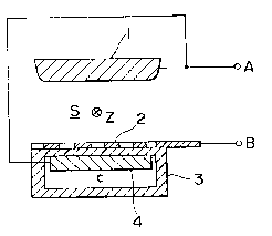
In Figs. 1 and 2, character Z indicates the optical
axis direction of laser beam. A pair of main discharge
electrodes, that is, an anode 1 and a cathode 2 are arranged
opposedly to each other over the optical axis. The cathode
2 is in the form of a lattice or comb. A dielectric 3 is
arranged opposedly of the cathode 2 and externally of the
anode 1 and the cathode 2.
The dielectric 3 is formed of ceramics and, as shown in
ZC~75S
Fig. 3, formed into a square pipe by Jolnlng a rod-like
member 3c having a n- shaped section with wall portions 3b
extended from opposite sides of a flat plate-like portion 3a
opposed to the cathode 2 toward one of the flat plate-like
portion 3a, and flat plate-like cover member 3d for covering
the open side of the n-shaped rod-like member 3c. Both
surfaces of the flat plate-like portion 3a are subjected to
mirror surface polishing so that the difference of level
between high and low portions is of the order of 5 ~ m.
Preferably, the ~oining surface of the rod-like member
3a and the cover member 3d is applied with mirror surface
working. Thereby it is possible to suppress the
deterioration of insulation from the interface.
The cathode 2 is placed in close contact with the
outer surface of the flat plate-like portion 3a.
On the other hand, an auxiliary electrode 4 having a
flat shape in section is embraced within the dielectric 3
leaving a space C in a manner such that the electrode 4 is
opposed to the cathode 2 and has the flat plate-like portion
3a sandwiched therebetween. This auxiliary electrode 4 is
along with and in close contact with the inner surface of
the flat plate-like portion 3a.
In Fig. 1, character A designates an electrode
terminal connected to the anode 1 and the auxiliary electrode
4, and character B designates an electrode terminal connected
to the cathode 2.
--6--
ZC~755
Next, the laser generatlng operatlon In the
aforementioned construction of apparatus will be described.
When a pulse-like voltage which is high voltage and
short pulse, for example, approximately 30 kv and about 100
nsec, is applied to the electrode terminals A and B, a
portion between the cathode 2 and the auxiliary electrode 4
functions as a condenser at riser portion of said pulse to
generate an auxiliary discharge. This auxiliary discharge is
a corona discharge generated in an opening of the cathode 2
via the dielectric 3. At that time, in the construction of
the present embodiments, the contact between the cathode 2
and auxiliary electrode 4 and the dielectric 3 as above-
mentioned is good and the capacity of a condenser formed
from the cathode 2, the dielectric 3 and the auxiliary
electrode 4 is enhanced, and therefore a large corona
discharge current flows (Fig. 4, a-b).
A large quantity of electrons are supplied to the main
discharge space S by the photo-ionization effect caused by
ultraviolet light generated from the auxiliary dishcarge
(corona discharge) and the effect in which electrons from the
discharge are moved to the main discharge space S via the
cathode 2 (preliminary ionization).
Next, when the pulse voltage applied between the
electrode terminals A and B further rises, the main discharge
starts (Fig. 4, point _). At this time, the laser gas
supplied to the main discharge space S is excited. and the
- , ~ : -
2C~7S6
laser beam is oscillated in the Z directlon in Fig. 1, The
Fig. 4 (point b) ls 15 to 30 kv.
In case of KrF excimer laser device, the laser gas used
comprises a mixture of He, Ne, Kr and F2 in a predetermlned
ratio. By altering the kinds of the laser gas, the
oscillation waveform of the laser beam can be changed. In
the present embodiments, XeCl, ArF excimer laser and so on in
addition to the KrF excimer laser can be used.
In the embodiment wherein a square pipe-like
dielectric is constituted by a rod-like member having a n-
shaped section with wall portions extended from opposite
sides of a flat plate-like portion toward one of the flat
plate-like portion and a flat plate-like cover member for
covering the open side of said rod-like member, an input
energy of 4.8J and an output energy of 140mJ are obtained
and the oscillation was carried out with high efficiency of
3%.
INDUSTRIAL APPLICABILITY
According to the present invention, there is provided
a discharge exciting excimer laser device in which a
dielectric is formed to be cylindrical and the side thereof
opposed to the main discharge electrodes is in the form of a
flat plate-like portion, and a auxiliary electrode is
embraced within the dielectric leaving a space and opposed to
one of the main discharge electrodes. With this arrangement,
the preliminary ionization electron density can be increased
: : ~ . ~. `, `' :
~ ;
2C5~7S5
to enhance the output of the laser beam and lmprove the
lnsulating performance. Accordlngly, the devlce ls suitable
for uses whlch rèquire a hlgh output.
The exclmer laser devlce of the present inventlon
can be used, for example, ~or a llght source ~or a
llthography, flne worklng of varlous materlals (includlng
borlng worklng and surface modlflcatlon of varlous
materlals), a laser anneal and the llke.
: ::
'
:
.
, , - ~ -