Language selection

Search

Patent 2054920 Summary

Third-party information liability

Some of the information on this Web page has been provided by external sources. The Government of Canada is not responsible for the accuracy, reliability or currency of the information supplied by external sources. Users wishing to rely upon this information should consult directly with the source of the information. Content provided by external sources is not subject to official languages, privacy and accessibility requirements.

Claims and Abstract availability

Any discrepancies in the text and image of the Claims and Abstract are due to differing posting times. Text of the Claims and Abstract are posted:

  • At the time the application is open to public inspection;
  • At the time of issue of the patent (grant).
(12) Patent Application: (11) CA 2054920
(54) English Title: PLANT FOR THE PRODUCTION OF MOLTEN METALS
(54) French Title: INSTALLATION DE PRODUCTION DE METAUX LIQUIDES
Status: Deemed Abandoned and Beyond the Period of Reinstatement - Pending Response to Notice of Disregarded Communication
Bibliographic Data
(51) International Patent Classification (IPC):
  • F27B 1/20 (2006.01)
  • C21C 5/56 (2006.01)
  • F27D 3/00 (2006.01)
  • F27D 99/00 (2010.01)
(72) Inventors :
  • PIRKLBAUER, WILFRIED (Austria)
  • WEBER, ALFRED (Austria)
  • AUER, JOHANN (Austria)
(73) Owners :
  • VOEST-ALPINE INDUSTRIEANLAGENBAU GMBH
(71) Applicants :
  • VOEST-ALPINE INDUSTRIEANLAGENBAU GMBH (Austria)
(74) Agent: SMART & BIGGAR LP
(74) Associate agent:
(45) Issued:
(22) Filed Date: 1991-11-04
(41) Open to Public Inspection: 1992-05-20
Availability of licence: N/A
Dedicated to the Public: N/A
(25) Language of filing: English

Patent Cooperation Treaty (PCT): No

(30) Application Priority Data:
Application No. Country/Territory Date
A 2334/90 (Austria) 1990-11-19

Abstracts

English Abstract


ABSTRACT OF THE DISCLOSURE:
A plant for the production of molten metals
includes a melting vessel in whose wall burners and
optionally oxygen-containing-gas feeding ducts are
installed and on whose upper end a charging device as
well as a gas evacuation duct receiving the offgases
forming enter.
In order to enable the continuous charging of the
melting vessel by avoiding any unintentional escape of
gas from the melting vessel, both the gas evacuation
duct and the charging means run into the upper end of
the furnace shaft laterally and approximately
diametrically opposite each other. The charging means
projects into a charging opening brushed over by a gas
curtain and an intake chute for charging material is
provided below the charging opening in a manner
directed towards the center of the furnace shaft. The
intake chute forms a projection protruding inwardly
like a nose relative to the wall of the furnace shaft
and followed by a wall section inclined relative to the
lower end region of the furnace shaft and passing over
into the wall of the furnace shaft.


Claims

Note: Claims are shown in the official language in which they were submitted.

THE EMBODIMENTS OF THE INVENTION IN WHICH AN EXCLUSIVE
PROPERTY OR PRIVILEGE IS CLAIMED ARE DEFINED AS FOLLOWS:
1. In a plant for the production of molten metals,
such as steel, and of the type including a molting
vessel having a vessel lower end region including a tap
opening for molten metal, a wall defining a furnace
shaft having a furnace shaft lower end region, said
wall accommodating burners and optionally oxygen-
containing-gas feeding ducts, and a furnace shaft upper
end including a charging opening and a gas evacuation
mouth, a charging means and a gas evacuation duct
receiving offgases forming running into said furnace
shaft upper end, the improvement wherein both said gas
evacuation duct and said charging means run into said
furnace shaft upper end laterally and approximately
diametrically opposite, said charging means projecting
into said charging opening and said charging opening
being brushed over by a gas curtain, and which further
comprises an intake chute provided below said charging
opening for charging stock and directed to the center
of said furnace shaft by forming a nose-like projection
protruding inwardly relative to said wall of said
furnace shaft, a wall section following upon said
projection and being inclined relative to said furnace
shaft lower end region, said wall section passing over
into said wall of said furnace shaft.

2. A plant as set forth in claim 1, wherein said
intake chute has an intake chute lower end arranged on
a height level on which said gas evacuation duct mouth
enters into said furnace shaft by its lower rim.
3. A plant as set forth in claim 1, wherein said
intake chute has an intake chute lower end arranged
closely below a height level on which said gas
evacuation duct mouth enters into said furnace shaft by
its lower rim.
4. A plant as set forth in claim 1, further
comprising a gas duct peripherally surrounding said
charging opening and including gas outlets directed
into the interior of said furnace shaft for forming
said gas curtain.
5. A plant as set forth in claim 1, wherein said
charging means is designed as a continuous conveying
means reaching through said charging opening as far as
to the starting region of said intake chute.
6. A plant as set forth in claim 5, wherein said
continuous conveying means is a vibrating channel.
7. A plant as set forth in claim 5, further
comprising an enclosure following upon said charging

opening for surrounding said continuous conveying
means.
8. A plant as set forth in claim 1, wherein said
intake chute is comprised of a massive steel plate.
9. A plant as set forth in claim 8, wherein said
massive steel plate is a steel slab.
10. A plant as set forth in claim 1, further
comprising at least one suspended apron provided
outside of said charging opening.
11. A plant as set forth in claim 7, further
comprising a gas duct peripherally surrounding said
charging opening and including gas outlets directed
into the interior of said furnace shaft for forming
said gas curtain and an air suction means provided
within said enclosure and flow-connected with said gas
duct.

Description

Note: Descriptions are shown in the official language in which they were submitted.


20~4~2~
The inventlon relates to a plant for the
productlon sf molten metals, in partlcular of steel,
comprising a meltlng vessel in whose lower end region a
tap opening is provided for molten metal, in whose wall
defining a furnace shaft burners and, if desired, ducts
feeding oxygen-containing gases are installed, and on
whose upper end a charging means as well as a gas
evacuation duct receiving the offgases forming enter.
A plant of this type is known from EP-A 2 321 443.
With this known plant, the melting vessel is designed
as a tiltable converter continuously smelting scrap
and/or pig iron. The charginq of scrap is effected via
a scrap chute, the evacuation of gases is effected via
a conv~rter offgas system.
With conventional melting vessels, problems arise
in the charging region, in particular when charging
lumpy material, such as automobile scrap in the baled
form. For reasons of temperature constancy and in order
to ensure a uniform flow of the melt, continuou
charging is suitable for continuous melting. In doing
so, the charged material constantly falls onto a
charged burden already present in the interior of the
melting vessel, thus saving the brickwork of the
melting vessel. Another problem is to be seen in that
the escape of offgases is hardly avoidable during
charging, in particular if charging proceeds
continuously. To avoid the escape of gases is of

205~20
particular interest if low-grade or heav~ly
contaminated scrap is to be meltsd.
The invention aims at avoiding these disadvantages
and difficulties and has as its ob~ect to provide a
plant of the initially defined kind, $n which the
charging material, in particular scrap, can be
introduced into the melting vessel in a csntinuous
manner by reliably avoiding the escape of offgases at
the charging means.
In accordance with the invention, this object is
achieved in that both the gas evacuation duct and the
charging means run into the upper end of the furnace
shaft laterally and approximately diametrically
opposite each other, wherein the charging means
pro~ects into a charging opening brushed over by a gas
curtain and an intake chute for charging material is
provided below the charging opening in a manner
directed towards the center of the furnace shaft, which
intake chute forms a projection protruding inwardly
like a nose relative to the wall of the furnace shaft
and followed by a wall section inclined relative to the
lower end region of the furnace shaft and passing over
into the wall of the furnace shaft.
According to a preferred embodiment, the lower end
of the intake chute is arranged on a helght level on
which the lower rim of the mouth of the qas evacuation

20~9?,~
means into the furnace shaft is located, or slightly
below.
Advantageously, a gas duct peripherally
surrounding the charging opening is provided to form
the gas curtain, including gas outlets directed into
the interior of the furnace shaft.
Suitably, the charging arrangement is comprised of
a continuous conveying means, such as a vibrating
channel, which reaches through the charging opening as
far as to the starting region of the intake chute.
As an additional safety measure, the conveying
means advantageously is surrounded by an enclosure
following the charging opening.
To ensure its optimum durability, the intake chute
suitably is formed by a massive steel plate, such as a
steel slab.
A curtain-apron provided externally of the
charging opening advantageously constitutes an
additional means of protection against the escape of
gas.
A preferred embodiment is characterized in that an
air suction means is provided within the enclosure,
which is in flow-connection with the gas duct
surrounding the charging opening, thus being able to
generate a negative pressure within the enclosure as a
further safety measure against the escape of gas.

Thereby, even str~ngly pulsedly 1ncurring offgases can
be controlled.
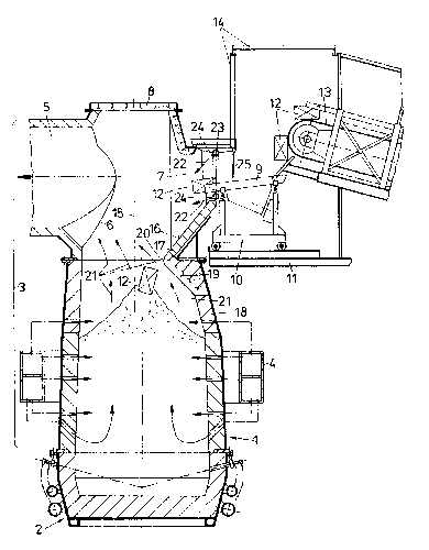
In the following, the invention will be explained
in more detail by way of an exemplary embodiment with
reference to the accompanying drawing, which
illustrates in section an installation for continuously
producing molten steel or a steel pre-product.
A stationarily supported refractorily lined
melting vessel l comprises a bottom part 2 and a
furnace shaft 3 following upon the bottom part. The
furnace shaft 3 of the melting vessel is surrounded by
an annular frame 4 stationarily mounted to a platform,
on which it is supported via brackets (not
illustrated). This annular frame 4 is designed to be
hollow, its cavity serving to supply the media
necessary for operating of the melting vessel
(combustion gases, oxygen-containing gases, etc.).
A gas duct 5 laterally runs into the upper end of
the furnace shaft 3. A charging opening 7 is provided
approximately diametrically opposite the mouth 6 of the
gas duct 5. The furnace shaft 3 is upwardly closed by a
lid 8.
A continuous conveying means 9 designed as a
vibrating chute protrudes into the charging opening 7
and is supported on a car 10, which is displaceable in
the horizontal direction on a charging platform 11 for
furnace maintenance purposes. The stock to be chargsd,

2~492~
such as, e.g., bales of scrap 12, reach the vibrating
chute 9 ~y means of a conveying belt 13. Both the
conveying belt 13 and the vibratinq chute 9 are
surrounded by an enclosure 14 closely following upon
the charging opening 7.
Below the charging opening 7, an intake chute 16
is provided, which is oriented obliquely to the center
15 of the furnace shaft 3 and is formed by a massive
steel plate, such as a slab. Via this intake chute 16,
the charging stock 12 reaches approximately the center
15 of the furnace shaft 3. A wall part 19 follows upon
the lower end 17 of the intake chute 16, connecting
this end 17 with the wall 18 of the furnace shaft 3 and
directed towards the bottom of the melting vessel.
The wall part 19, together with the intake chute,
forms a nose-like pro~ection 20 protruding far into the
interior of the furnace shaft 3, through which the
gases formlng in the melting vessel 1 and in~ected into
the melting vessel are conducted in the direction of
arrows 21 to the mouth 6 of the gas evacuation duct 5
located opposite the projection 20. The lower end 17 of
the intake chute 16 and the wall part 19 following upon
this end are located at a level immediately below the
lower rim of the mouth 6 of the gas evacuation duct 5.
The charging opening 7 is sealed by a gas curtain
22. A gas feed 23 is provided for the formation of this
gas curtain 22 along the rim of the charging opening 7,

2~$~92~
including gas outlets 24 directed towards the interior
of the furnace shaft 3, through which the fed gas -
preferably air sucked in from the enclosure 14 by a
suction means - flows obliquely towards the center 15
of the furnace shaft 3.
This gas curtain 22, together with the nose-like
projection 20, ensures the furnace offgases to be
safely conducted into the gas evacuation duct 5. Aprons
and curtains 25 arranged beyond the charging opening 7
may be provided as additional measures such that no
offgases will escape even if incurred pulsedly, but a
short-term accumulation of the offgases in the upper
part of the furnace shaft 3 is rendered possible.
~he melt forming in the melting vessel is
continuously drawn off via a tap hole (not illustrated)
and, if desired, is conducted into a metallurgical
vessel for aftertreatment.

Representative Drawing
A single figure which represents the drawing illustrating the invention.
Administrative Status

2024-08-01:As part of the Next Generation Patents (NGP) transition, the Canadian Patents Database (CPD) now contains a more detailed Event History, which replicates the Event Log of our new back-office solution.

Please note that "Inactive:" events refers to events no longer in use in our new back-office solution.

For a clearer understanding of the status of the application/patent presented on this page, the site Disclaimer , as well as the definitions for Patent , Event History , Maintenance Fee  and Payment History  should be consulted.

Event History

Description Date
Inactive: IPC deactivated 2011-07-26
Inactive: IPC from MCD 2010-02-01
Inactive: IPC expired 2010-01-01
Inactive: IPC from MCD 2006-03-11
Application Not Reinstated by Deadline 1998-11-04
Time Limit for Reversal Expired 1998-11-04
Deemed Abandoned - Failure to Respond to Maintenance Fee Notice 1997-11-04
Application Published (Open to Public Inspection) 1992-05-20

Abandonment History

Abandonment Date Reason Reinstatement Date
1997-11-04
Owners on Record

Note: Records showing the ownership history in alphabetical order.

Current Owners on Record
VOEST-ALPINE INDUSTRIEANLAGENBAU GMBH
Past Owners on Record
ALFRED WEBER
JOHANN AUER
WILFRIED PIRKLBAUER
Past Owners that do not appear in the "Owners on Record" listing will appear in other documentation within the application.
Documents

To view selected files, please enter reCAPTCHA code :


To view images, click a link in the Document Description column. To download the documents, select one or more checkboxes in the first column and then click the "Download Selected in PDF format (Zip Archive)" or the "Download Selected as Single PDF" button.

List of published and non-published patent-specific documents on the CPD .

If you have any difficulty accessing content, you can call the Client Service Centre at 1-866-997-1936 or send them an e-mail at CIPO Client Service Centre.


Document
Description 
Date
(yyyy-mm-dd) 
Number of pages   Size of Image (KB) 
Abstract 1992-05-20 1 24
Cover Page 1992-05-20 1 13
Claims 1992-05-20 3 71
Drawings 1992-05-20 1 28
Descriptions 1992-05-20 6 159
Representative drawing 1999-06-28 1 25
Courtesy - Abandonment Letter (Maintenance Fee) 1997-12-02 1 186
Reminder - Request for Examination 1998-07-07 1 129
Fees 1996-10-28 1 73
Fees 1995-10-16 1 68
Fees 1994-10-13 1 67
Fees 1993-10-15 1 42