Note: Descriptions are shown in the official language in which they were submitted.
2 0 ~
BACRGROUND OF ~ INVBNTION
The invention is directed to an electromagnetic relay having
a housing, terminal elements guided out of the housing, and a
control module in the form of an integrated circuit arranged in the
housing.
It is already known in an electromagnetic relay to
accommodate a control module in an outwardly open chamber of the
bottom plate, the terminal pins of this control module being
arranged parallel to the terminal pins of the relay (DE 36 14 919
C2). As long as this known relay is operated in normal ambient
temperatures, the control module having electronic components will
also not heat to an impermissible degree, so that the function is
guaranteed. Given this and other known relays having integrated
circuits arranged within the housing, however, reliable operation
has previously only been guaranteed when the thermal stress due to
coil heating and contacts as well as ambient temperature does not
proceed beyond the loadability of the electronic components. Such
integrated circuits can only be loaded up to an upper limit
temperature of 150~C. Temperatures proceeding beyond this
considerably shorten the useful life of these components.
Given relays for specific purposes, however, there is the
need for a regulation of the control voltage or of the coil current
given a simultaneously high thermal loading due both to high
switching currents in the interior of the relay as well as due to
high ambient temperatures. A typical application for such a relay
ls a motor vehicle wherein the contacts must carry extremely high
currents at low voltages, while the ambient temperature fluctuates
greatly and, for example, can amount to up to 125C. When the
self-heating of the relay is then added, thermal loads up to 200C
2 ~
thus result, temperatures which an integrated circuit cannot
withstand. A regulation of the control vo~tage, however, i5
desirable or required precisely because of the great temperature
fluctuations. Thus, one would also liXe to accommodate the control
modules in the relay housing in this case as well as for saving
space and assembly work.
~U~MARY OF T~E INVBN~ION
It is an object of the invention to create a relay of the
type initially cited having an integrated circuit as a control
module accommodated in th~ relay housing. The harmful influences
of elevated temperatures, whethar due to dissipated heat in the
coil and contacts or due to the self-heating of the circuit, can
be eliminated or at least significantly alleviated with optimally
low structural expense.
This ob~ect is achieve.d in that at least one of the terminal
elements designed as a flat plug is utilized as a cooling plate
which has a coupling section at its ~lat side thermally coupled to
the substrate of the integrated circuit.
Due to the employment according to the invention of one or
more flat plugs in the relay as a cooling plate for the integrated
circuit, an efficient heat elimination can occur without requiring
additional parts. The flat plugs are employed as a standard, for
example for motor vehicle relays, and have a standardizPd width of
6.3 or 9.5 mm, given a thickness of 0.8 to 1.2 mm. Such a large
cross section makes a good heat elimination possible since the
cabling connected to the flat plug via a plug-in socket or via a
cable shoe continues to carry the heat away. In previous relays,
the large cross section of the flat plugs for the terminal elements
~5~
of the contacts is important because of the high switching
currents, whereas the coil tPrminals need only basically carry a
relatively low current. According to standards, however, the coil
terminal flat plugs have the same cross section. An additional,
advantageous utilization of this large plug cross section that is
already present for heat elimination thus results for the control
module to be connected to the coil.
When the integrated circuit is arranged on a base plate of
the housing or in a depression of the base plate, then the coupling
section of the. flat plug is preferably arranged above it such that
the circuit is shielded from heat sources in thP relay. The
thermal coupling between the integrated circuit and the flat plug
can thus be undertaken with a thermally conductive paste or with
other means when the integrated circuit and the flat plug are
mounted as discrete parts. However, it is also possible to provide
the integrated circuit with an integrated cooling plate of one
piece construction therewith from the very outset in the fashion
of a power semiconductor, the flat plug being integrally applied
to this cooling plate as a continuation thereof. ln this case, one
terminal of the circuit can be directly electrically contacted to
the cooling plate or to the flat plug.
In a ~urther development of the invention, the integrated
circuit can also be arranged in flat thermally conductive coupling
between parallel coupling sections of two flat plugs, whereby it
is firmly joined to at least one of the flat plugs. In this case,
thus the heat elimination is undertaken via two flat plugs, and
thus even more efficiently. When the materials allow it, tha
integrated circuit can be firmly joined to hoth flat plugs, whereby
one respective terminal of the circuit is contacted with one of the
2 ~ @ ~
flat plugs. When, however, a relative motion due to thermal
expansion of the various parts mus~ be taken into consideration,
then only one of the flat plugs is firmly joined to the integrated
circuit, whereas the second flat plug is loosely coupled but
likewise in thermally conductive fashion and is contacted to the
corresponding terminal element of the integrated circuit via a
flexible connection.
The integrated circuit together with the respective coupling
section of the flat plug or flat plugs can be at least partially
arranged within the base plate, and preferably embedded thersin.
Various ways of fastening are possible. Given plugging into
rece~ses o~ the base plate, the remaining openings can be closed
with casting compound, the flexible connections, for example, being
thereby covered and sealed. This is particularly advantageous when
the plugging or the embedding of the flat plugs together with the
integrated circuit is undertaken in the region of a depression that
iæ only accessible proceeding from the outside of the relay
housing. A subsequent sealing is desirable in this case in all
instances.
~RI~F DE8CRIP~TON 0~ TH~ DRA~I~G~
Figure 1 shows a fundamental circuit of a control circuit
having a coil in a relay housing;
Figure 2 is a schematically illustrated relay housing having
a shielded integrated circuit in the region of a base plate;
Figures 3 and 4 illustrate a portion of a base plate having
a flat plug which, as a cooling plate, forms a uniform component
with an inteyrated circuit; and
Figures 5 through 7 show an arrangement of an integrated
circuit between two cooling plates in various positions in a base
plate.
2 ~
DE~CRIPTIO~ O~ THE PREFERRED EMBODI~NT~
Figure 1 fundamentally shows the connection of a control
module in the form o~ an integrated circuit l for the drive o~ a
control coil 2 in a relay. The coil terminals 3 and 4 thus lead
toward the outside, these coil terminals 3 and 4 being partly
directly and partly indirectly connected in the inside of the relay
to the coil 2 via the three terminals 11, 12, and 13 of the
integrated circuit.
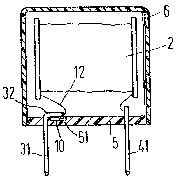
In a schematic, sectional view of a relay housing having a
cap 6 and a base plate 5, Figure 2 shows the arrangement of the
coil 2 and its connection to the coil terminals 3 and 4 which are
designed as flat plugs 31 and ~1. At the inside of the base plate
5, the flat plug 31 has a bent-off coupling section 32 that shields
the integrated circuit lO arranged in a depression 51 of the base
plate 5 from the coil and from other heat sources (not shown) in
the relay. A good thermal connection between the integrated
circuit 10 and the coupling section 3:2 of the flat plug is produced
wi~h a thermally conductive paste 52.
Figures 3 and 4 show an integrated circuit 1 that is
manufactured as a one-piece component with a coupling section 32
in the form of a cooling plate, whereby the flat plug 33 is
immediately applied to this cooling plate. The cooling plate in
the form of the coupling section 32 thereby directly forms the
circuit terminal 11 of Figure 1, whereas the two terminals 12 and
13 are separately guided out. The cooling plate in the form of the
coupling section 32 can, according to Figure 3, be vertically
anchored with the flat plug 31 in the base plate 5 or, according
to Figure 4, can be anchored in the base plate 5 in angled-off
fashion.
2 0 ~
Figures 5 and 7 show an embodiment wherein an angled-off
coupling section 32 of the flat plug 31 and an angled~off, second
coupling secton 42 of the flat plug ~1 overlap one another in
parallel. The integrated circuit lO is inserted in the overlap
region between these two coupling sections, whereby it is firmly
joined to the coupling section 32, but is only loosely and also
thermally conductively joined to the coupling section 42. The heat
elimination can thereby also be assured by a thermally conductive
paste. Since the coupling section 42 also requires an electrical
connection to the terminal 13 of the integrated circuit 10, this
connection 13a is flexibly designed and separately contacted. In
this exemplary embodiment, the two flat plugs have their coupling
sections 32 and 42 firmly anchored in the base plate 5 by plugging
or embedding, whereby the flexible connection 13a and the terminal
12 conducted to tha coil are accessible in an opening 7 toward the
inside of the housing. If necessary, this opening can be
subsequently cloæed or extrusion-coated by casting compound or the
like.
Figure 6 shows a similar arrangement of the flat plugs 31
and 41, whereby a firm coupling between the integrated circuit 10
and the coupling section 42 is provided in this case. A loose
coupling ls thus formed between the integrated circuit lo and the
coupling section 32. The terminal 11 of the integrated circuit in
this case is therefore contacted to the coupling section 32 via a
flexible connection lla.
The arrangement of Fi~ure 6 is modified in Figure 7 to the
extent that an embedding or other anchoring of the coupling
sections 32 and 42 is now undertaken such that a depression 8 is
accessible from the outside. In order to protect the flexible
2 ~
connections 12a and 13a in this case, ~his depression can be
subsequently closed with a casting compound 9. However, it is also
conceivable in this case to embed the flat plugs and the integrated
circuit in common into the base plate 5 such that all terminals are
insulated and sealed Erom the very outset.
Although various minor changes and modifications might be
proposed by those skilled in the art, it will he understood that
I wish to include within the claims of the patent warranted hereon
all such changes and modifications as reasonably come within my
contribution to the art.