Note: Descriptions are shown in the official language in which they were submitted.
..
1 H~CR(3~dOWtD O~ R~ IH~~JTI~~i
2
~s ~~~1~ ~~ ~~~ I~~~~~~~at
4
The invention relates generally to inflatable
6 packers or bridge plugs far use in subterranean
7 wellbores, and specifically to inflatable packers or
8 bridge plugs which are allowed to move axially in
3 response tc~ inflation forces produced through the
to introduction of pressurized fluid into an inflation
1 1 spa Ce .
12
1.3 ~. . H~scription of the i~rior l~rts
14
Known prior art inflatable packing devices
15 include annular inflatable cover which usually
37 comprises an inner fluid-tight flexible sleeve covered
18 by a plurality of axially aligned and overlapping
19 reinforcing ribs (or slats).
21 During a running mode, wellbore packers are
22 placed in position within a wellbore. Frequently, the
23 wellbore packax is exposed to rotational farces which
24 twist the reinforcing ribs cut ot" axial alignment, and
which may allow the inner fluid-tight flexible sleeve
26 to extrude through the reinforcing ribs during the
27 inflation pracess. This presents a danger of injury to
28 the inner fluid-tight flexible sleeve, which can be
29 costly to remedy. This danger is discussed in greater
3~ detail below in connection with figures 1 and 2.
0
1 ~~' p~' T~ aa~z~Tao~
2
3 It is one objective of the present invention
4 to provide an inflatable packing device far use in a
b wellbore which inhibits the twisting of one end of the
6 inflatable packing device relative to the other end,
7 until a predetermined amount of inflation has occurred.
m 8
~ It is another object of the present invention
l0 to provide an inflatable packing device for use in a
11 wellbore, which is prevented groan twisting prior to
12 inflation by a plurality of shearable locking members
13 disposed at one end of said inflatable packing device.
14
It is yet another objective of the present
r 16 invention to provide an inflatable packing device for
17 use in a wellbore which is inhibited from twisting
18 during a deflated running made, until the packer is
19 axially contracted by inflation during the transition
20 between said deflated running mode and an inflated
21 setting mode and anti-rotation pins are sheared.
22
23 These and other objectives are achieved as is
24 now described. An inflatable packing tool is provided
25 for use in a subterranean wellbore. The inflatable
26 packing tool is coupled to a wellbore conduit with a
27 central bore which directs pressurized fluid into the
28 e~ellbore. The inflatable packing tool includes a
29 central tubular body for directing fluid in the
30 wellbore. Upper and lower ~tatior~ary caller members
31 are secured to the central tubular body for coupling
32 the central tubular body to the wellbore conduit. An
33 annular inflatable packing element surrounds the
. 3 r
CA 02055173 2002-07-26
73818-30
1 central tubular body, and includes a flexible fluid-
2 tight sleeve covered by a plurality of overlapping and
3 axially extending reinforcing ribs. A slidable sleeve
4 assembly is coupled to one end of the annular
inflatable packing element. A locking means is
6 provided for fixing the position of the slidable sleeve
7 assembly during a deflated running mode to prevent
8 axial movement of the slidable sleeve assembly relative
9 to the central tubular body, rotational movement of the
l0 slidable sleeve assembly relative to the central
11 tubular body, and twisting of the plurality of
12 overlapping and axially extending reinforcing ribs out
13 of axial alignment with the central longitudinal axis-
14 of the central tubular body. A valve means is provided
for inflating the annular inflatable packing element
16 with pressurized fluid from the wellbore conduit during
17 an inflation mode. Through operation of the valve
18 means, the annular inflatable packing element is
19 prevented frog inadvertent inflation during the running
2o mode as the inflatable packing tool is lowered into the
21 wellbore. The plurality of overlapping and axially
22 extending reinforcing ribs are prevented from twisting
23 out of axial alignment in response to rotational forces
24 and hence from damaging the annular inflatable packing
element, and especially from damaging the flexible
26 fluid-tight sleeve of the annular inflatable packing
27 element.
~ 4
CA 02055173 2002-07-26
73818-30
4a
In summary, the invention provides an inflatable
packing tool for use in a subterranean wellbore when coupled
t;o a wellbore conduit with a central bore for directing
presssurized fluid in said wellbore, comprising, in
combination: a central tubular body for directing fluid in
~~aid wellbore, defining a central longitudinal axis; upper
and lower stationary collar members secured to said central
tubular body for coupling said central tubular body to said
wellbore conduit; an annular inflatable packing element
surrounding said central tubular body, inc:lud:ing a flexible
f=luid-tight sleeve covered by a plurality of overlapping and
axially extending reinforcing ribs; a slidablE=_ sleeve
assembly coupled to one end c>f said annular inflatable
packing element; a locking means for fixing the pasition of
said slidable sleeve assembly during ~-~ deflated running mode
to prevent: a) axial movemerzt of said sl:idab:le sleeve
assembly relative to said central tubular body; b)
rotational movement of said slidable sleeve assembly
relative to said central tubular body; and c) twisting of
said plurality of overlapping and axially extending
reinforcing ribs out of axial alignment withsaid central
longitudinal axis of said central tubular body; a valve
means for inflating said annular .inflatable packing element
with pressurized fluid from said wellbore conduit during an
inflation mode; and whereby said annular inflatable packing
Element is prevented from inadvertent inflation during said
running mode as said inflatable packing tool is lowered in
said wellbore, and said plurality of overlapping and axially
Extending reinforcing ribs are prevented from twisting out
of axial alignment in response to rotational forces and
damaging said annular inflatable packing element, and
Especially from damaging said flexible fluid-tight sleeve of
said annular inflatable packing element.
CA 02055173 2002-07-26
73818-30
4b
The above as well as additional features, and
advantages of the invention will become apparent in the
following detailed description.
2~~~~~."~~~
HRIE~' nEBCRgPTZ~D1 Q~' TH~ D~.~~NCi
2
3 The novel features believed characteristic of
4 the invention are set forth in the appended claims,
The invention itseli~ however, as well as a preferred
6 mode of use, further objects and advantages thereof,
7 will best be understood by reference to the following
8 detailed description of an illustrative embodiment when
g read in conjunction with the accompanying drawings,
1o wherein:
11
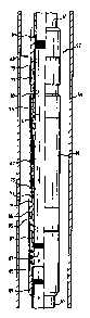
12 lr3guxe l is a simplified partial-cutaway view
13 of a prior art external casing packer (LCP' disposed
14 within a wellbore, which graphically depicts the
1~ rotation forces acting upon the ECP;
l~
r
1' P3gur~ 2 is a mare detailed view of a prior
r
18 art external oaring packer in one-quarter longitudinal
19 section, with the outer elastomerio cover of the ECP
20 removed to illustrate one problem encountered by prior
21 art packers;
' 22
23 ~39tur~ 3 is s one-cpaarter longitudinal
24 section view of the eacternal oaring packer oil the
2S present invention, shown in deflated running mode;
2~
2'1 ~'ic~ur~ .6 is a one-quarter longitudinal
28 section view of the upper cylindrical. collar assembly
29 of the improved wellbore packer of the present
30 .invention;
31
32 ~'igur~ 5 is a cross-section ~riew of the upper
33 cylindrical collar of ~igura 4 as seen along line A-A;
~o~~~~~
F3.c~ura 6 is a longitudinal section view of
3 the upper stationary collar piece of l~igura 9t
~igurs ~ is a longitudinal view of the
E cylindrical shear sleeve of 8iguae ~; and
~'igur~ ~ is a one-quarter longitudinal
9 section view of the' external casing packer of the
1~ present invention, shown in an inflated setting amode.
~~ i~~."t
1 Dsx~x~so o~sc~tx~rxoW o~ x~a x~tv~rrxxoW
2
3 Figur~s 1 and a illustrate one problem with
prior art wellbore packers. With reference nor to the
figures and in particular with reference to ~ig-aar~ 1.,
6 welibore packer 11 is shown disposed within wellbore
7 13, which extends into formation 3l°~. Wellbore packer
8 1i is an external casing packer (EC1P) which is used to
9 set a casing in position within wellbore 13, and is
particularly useful in setting casing in deviated and
11 horizontal wellbores.
12
13 Wellbore packer i~. is shown in ~fc~ur~ 1 in
14 simplified form, and includes upper collar a? and lower
collar 19, which couple wellbore packer 11 to casing
16 string 21,. 6dellbors packer 1l includes a central
17 inflatable region ~3 which; serves to expand in response
15 to pressurized fluid, and inflates to frictianally
19 engage wellbore 13, and fix the position of wellbore
packer 1l. and casing string $1 above and below wellbore
21 packer 1~ within wea.Ibore i3.
22
23 Wellbore packer ri1, is shown in ~ic~ur~ l in
24 fragmentary section with outer eiastomeric cover a5 cut
away to expose far view the array of overlapping
26 expansion slats 2?. Expansion slats 2? overlie inner
2? elastomeric cover a9 (not depicted in ~'ig°ure 1.) , ~,s
28 inner elastomeric cover 2~ expands, the array of
29 overlapping expansion slats likewise expand and urge
outer elastomeric cover 35 into a frictional engagement
31 of wellbore 13,
32
a
_ ? _
CA 02055173 2002-07-26
73818-30
1 Often, a considerable amount of force is
2 required to position casing string zi in a desired
3 location. This is particularly true in deviated and
4 horizontal wellbores, and is also true if casing string
Zi must be passed through a "dogleg" in the wellbore.
6 As a consequence, wellbore packer ii frequently
7 experiences rotational forces, like the rotational
8 forces depicted in Figure 1 by force arrows 3i, 33. As
9 shown, rotational forces can oppose one another to
twist wellbore packer ii.
11
12 Figure 2 graphically depicf.s the detrimental
13 effect of such twisting on wellbore packer ii. For
14 purposes of exposition, wellbore packer ii is shown
with outer elastomeric cover removed, and in one-
16 quarter longitudinal section, while in an inflated
17 mode. As shown, fluid 11 is diverted from central bore
18 39 of wellbore packer ii through valve assembly 51 to
19 inflation region 35 between central tubular body 53 of
wellbore packer 11 and inner elastomeric cover 29.
21 Fluid 4i within inflation region 35 acts to expand
22 inner elastomeric cover Z9 radially outward, and
23 likewise acts to expand array of overlapping expansion
24 slats 27.
26 One type of prior art wellbore packer is
27 equipped with a known shearable sliding sleeve
28 assembly, such as the sliding sleeve assembly described
29 in U.S. Patent No. 4,832,120, entitled "Inflatable Tool
For A Subterranean Well," issued on May 23, 1989 to
31 Baker Hughes Incorporated. In this prior art
32 device a conventional inflatable packer or bridge plug
~~~~~."~~
1 is described: of course, the concepts of this reference
2 have been used in external casing packers. As stated
3 in this reference, a reinforced sleeve of elastomeric
4 material is mounted in surrounding relationship to a
tubular body, wfth one end of the sleeve fixed and
6 sealably secured to a tubular body and the other end
7 sealably and slidably affixed to the tubular body, the
8 slidable end is shearably secured to the tubular bady
9 so that a predetermined amount of axial tension must be
produced in the inflatable element to shear the
11 slidable end free.
12
13 When rotational. forces are applied to one or
14 both ends of such a wellbore packer 11, the array of
overlapping expansion slats 2? will not expand in an
16 even fashion, and will in fact be twisted. When the
1 17 .individual slats are twisted out of alignment, it is
18 possible for inner elastomeric sleeve 29 to extrude
19 through gaps between the slats, during the inflation
.r
process due to misalignment of the slats or ribs. In
21 ~'igur~ 2, such extrusion is depicted in wellbore packer
22 19., as extrusion 39. extrusion of inner elastomeric
23 cover 2~ is a very dangerous candition, since
24 expansion slate x7 can pinch, cut, or otherwise damage
the inner elastomeric cover 29, and ~eopardixe its
26 fluid-tight qualities. Once the inner elastomeric
27 cover 29 is punctured or otherwise damaged, wellbore
28 packer is becomes useless. This can be an expensive
29 and dangerous problem, especially when wellbore packer
3o a1 is used as an external casing packer to hold a
31 casing in place within a wellbore. The replacement of
32 a external casing packer can be an expensive and time
33 consuming task.
1
2 The improved wellbore packer with shearable
3 anti-rotation pins of the present invention is depicted
4 in figures 4 through ~. ~igura 3 depicts the unproved
wellbore packer 5' of the present invention in a
6 deflated running mode. ~icJur~ 5 depicts the improved
wellbore packer 57 of the present invention in an
inflated setting mode. pictures ~, 5, 6, and 7 depict
9 in greater detail the anti-rotational locking feature
to of the present invention. The present invention
11 relates not only to external casing packers but to
12 other types of inflatable packing devices for use in a
13 wellbore, but to simplify .the description, a single,
14 preferred embodiment is shown.
16 Turning now to ~igur~ 3, improved wellbore
17 packer 57 is shown disposed within wellbore 5!, either
1~ a cased or uncased wellbore. Improved wellbore packer
19 57 is shown coupled to casing string 6x at upper and
2o lower collar assemblies 6~, ~5. Upper collar assembly
21. is connected by threads 9~. to casing string ~1. ewer
22 collar assembly is coupled by threads i39 to cas~.ng
23 string 6a. Improved wellbore packer 5T includes a
24 central tubular body i~" which is also coupled to upper
and lower caller assemblies by threads 6~9, l~l.
26
27 Improved wellbore packer 57 further includes
2~ an annular inflatable packing element 69 which
29 surrounds a large portion of said central tubular body
3~ 6~. annular inflatable packing element 69 includes
31 inner flexible fluid-tight sleeve fig, an array of
32 overlapping and axially extending reinforcing ribs (or
33 slats) 73, and outer flexible sleeve ~5.
l0 -
CA 02055173 2002-07-26
'73818-30
1 particular reinforcing ribs utilized are described
2 generally in U.S. Patent No. 4,349,204, entitled "Non-
3 Extruding Inflatable Packer Assemb~.~r" issued on
4 September 14, 1982 to Lynes, Inc., U.S. Patent Nos,
b 3,581,816 and 3,604,732 to Malone also describe
7 generally the particular reinforcing ribs.,
8
9
Slidable sleeve assembly ?? is provided at
11 the upper end of improved wellbore packer 57.
12 Shearable locking means ?9 lacks slidable sleeve
13 assembly ?5 in place when improved wellbore packer 5?
14 is in a running mode.
16 Valve means 8i is disposed at the opposite
17 end of improved wellbore packer 5?, and serves to
18 direct fluid 41 from the central bore 83 of improved
19 wellbore packer to selectively inflate annular
inflatable packing elemsnt b9. Valve means 81 is a
21 conventional valuing system, such as that described in
22 U.S. Patent No. 3,437,142, entitled "Inflatable Packer
23 For External Use on Casing and Liners and Method of
24 Use," issued to G.E. Conover on April 8, 1969: this
patent is fully incorporated herein by reference.
26
Z7 The valve means 81 receives pressurized fluid
28 41 from central bore 83 of improved wellbore packer 57.
29 Fluid 41 is pumped downward from the surface through a
wellbore conduit, such as casing string 61. Valve
31 means 81 operates during an inflation mode to direct
32 pressurized fluid 41 from central bore 83 to an
33 inflation region 85, which is between inner flexible
- 11
1 fluid-tight sl~eeva ~a central tubular body
and ~?.
2 Pressurized fluid 41 whichis directed Intoinflation
3 region s5 operates to radially expand annular
4 inflatable packing element
~9 causing shearable locking
means 99 ~to shear and position
become unfixed in
6 relative to central tubularbony ~,.
~nce shearable locking means is sheared,
9 annular inflatable packing element 69 is allowed to
move axially relative to central tubular body 69.
11 Slidable sleeve assembly 7a is also then allowed to
12 move radially (or rotationally] relative to central
13 tubular body 69. Finally, the plurality of overlapping
14 and axially extending reinforcing ribs ~3 are allowed
to twist in response to rotational forces: however,
lf> sinc;e the improved wellbore packer 37 is at that time
17 set in a desired position, it is unlikely that the
18 reinforcing ribs ~3 will in fact twist or rotate.
Z9
Valve means S3 also serves to trap
21 pressurized fluid in inflatian region 85 between
22 central tubular body 6f and annular inflatable packing
23 element 69. When fully expanded, improved wellbore
24 packer ~T operates in a sett~,ng mode to fix the
position of easing string 1b1 relative to wellbore ~9.
2s
2~ Slidable sleeve assembly '77 and shearable
28 locking means ~9 cooperate to prevent the inadvertent
29 inflation of improved wellbore packer 57 during a
running mode in which improved wellbore packer 5'~ is
31 lowered into wellbore 59. wring the running mode, the
32 plurality of overlapping and axially extending
33 reinforcing ribs ~3 are prevented from twisting out of
_ 12 _
1 axial alignment in response to rotation forces and
2 ,damaging inner inflatable peaking element s9. Tn
3 particular, inner flexible fluid-tight sleeve ?1 is
4 protected from damage due to twisting of the plurality
of overlapping and axially extending reinforcing ribs
6 ?3.
7
8 Turning now to ~igur~ s, upper collar
9 assembly s3 will be discussed in much greater detail.
Upper collar assembly s3 includes stationary collar ~.Ol
11 which couples to casing string si and central tubular
12 body s? by internal threads 91,. stationary collar 191
13 is fixed in position relative to central tubular body
14 s?. Slidable sleeve assembly ?? includes cylindrical
seal housing 183 with O-ring seals 105, i~? provided in
16 seal cavities 10l, 111. O-ring seals 105, 10? serve to
17 slidably engage, and form a movable seal with, central
18 tubular body s?. Cylindrical seal housing 1~3 is
19 coupled to annular inflatable packing element s9 at
2o upper cylindrical end cover 9~. slidable sleeve
21 assembly ?? operates to move axially downward relative
22 to central tubular body s' when annular inflatable
23 packing element s9 is inflated with prestrurized fluid
24 si.
2s When improved wellbare packer 5? is lowered
2? within wellbore 5!, slidable sleeve assembly ?? must be
28 restrained from sliding to prevent annular inflatable
29 packing elements s9 from prematurely inflating in
response to localized high fluid pressure. Tn the
31 present invention, this is accomplished by shearable
32 locking means ?9. Tat the preferred embodiment,
33 shearable locking means includes cylindrical shear
-~ 1~ -
1 sleeve 113 which overlies at least a portion of central
2 tubular body 67 and is fixed in position relative to
3 central tubular body 67 during the deflated running
4 mode by a plurality o~ radially disposed sheorebla
members which extend through a plurality o~ openings
117 in cylindrical shear sleeve 113 into a plurality o~
7 radially disposed anchor cavities 1~.~ which are gixed
8 in position relative to central tubular body 67.
9
1~ ~igurs 5 is a section view of ~ic~ur~ 4 as
11 seen along line A-A. This view will aid in
12 understanding the preferred embodiment of the sheorebla
13 locking means 79. As shown, a plurality .of radially
14 disposed sheorebla members 11~ extend through a
35 plurality o~ openings 117 in cylindrical shear sleeve
16 113, and descend into a 'plurality o~ radially aligned
17 anchor cavities 119 disposed in the outer surface of
1~ upper stationary collar 101.
1g
2o ~ic~u~s 6 is a longitudinal section view o~
21 upper stationary collar 101. Internal threads 91 serve
22 to couple upper stationary collar loi to caring strong
23 61 and central tubular body 67. Anchor cavities ilk
24 are provided at the lower end o~ upper stationary
25 collar ~:~1. A slight lip or notch 121 is provided for
26 mating with cylindrical shear sleeve 113. figure 7 is
27 a longitudinal section view of cylindrical shear sleeve
2~ 313. cylindrical shear sleeve 113 includes two regions
29 0~ dil~erinc~ radial dimensions. ilpper region 123 of
30 cylindrical shear sleeve 113 has a radius o~ r1 and is
31 provided i'or slidably engaging the slightly enlarged
32 upper region 1.7 0~ cylindrical seal housing 1~3.
33 Iaower region 12~ o~ s;ylindrical shear sleeve 113 has a
1~
1 smaller radial dimension re, which is adapted for
2 slidably engaging narrow lower region 12g of
3 cylindrical seal housing 103. The notch 131 formed by
4 the difference in radial diameters r1 and rZ serves to
mate with notch 133 at the transition between enlarged
6 upper region 12~ and narraw lower region 124 of
? cylindrical seal housing 1A3.
8
~'i~lure 8 is a view of improved wellbore
packer ~~ of the present invention in an inflated
11 setting mode. ~s shawn~ radial expansion 133 of
la annular inflatable packing element 6~ causes downward
13 movement 135 of cylindrical seal housing 103. O-ring
14 seals 105, 107 maintain a tight seal against central
tubular body 67. Eventually, the downward forces
16 acting on cylindrical shear sleeve~113, in response to
17 downward pulling of cylindrical seal housing 103, will
18 cause shearable members 115 to shear.
19
aB In the preferred embadiment, shearable
21 members 115 comprise a plurality of threaded shear pins
2a of known shoat strength. Therefor~s, it is possible for
23 one to set a predetermined fluid pressure threshald
a~ upon whir~h all of shearablm members 115 will shear.
a5 ;3hear strength may be adjusted by known means, such as
a6 selecting the total rmmber of pans used, as well as the
a7 materials of construction for each shear pin and the
28 radial cross-section of each pin.
a~
3A When shearable members 8.15 yield to the
31 downward force, cylindrical shear sleeve 113 will break
32 free of upper stationary collar 1A1, and allow. annular
33 inflatable packing element 5~ to expand radially
1°6
~~
\
1 outward. The shear strength of shearable members 115
2 array be Selected to allow for the inflation ox improved
3 wellbore packer 5~ at a predetermined fluid pressure
4 level, to allow one to selectively change the mode of
operation of improved wellbore packer 57 from m
5 deflated running mode to an inflated setting made.
7
8 ~s stated above, the valve means of the
9 present invention is similar to that claimed and
described in U.S. Patent No. 3,437,142, entitled
11 "Inflatable Packer for External Use on Casing and
12 Liners and Method of Use," issued to G.E. Conover on
13 April 8, 1969. Essentially, valve means 81 prevents
14 the inflation ~f improved wellbore packer 5~ until a
predetermined pressure threshold has been passed.
16 Valve means 81 mlso includes a mechanism by which
17 pressurized fluid ~11 may be trapped within inflation
18 region 85 of improved wellbore packer 57. Valve means
19 81 will "lock" when a second, higher pressure level is
obtained.
21
22 Therefore, a relatively low pressure level
23 begins the valuing of pressurized fluid into inflation
24 region 85 of improved wellbore packer 59. ~ second,
higher gluid pressure level serves to expand annular
26 inflatable packing element 69 with sufficient force to
27 shear shearable members 115. Upon shearing of
28 shearable members 115, annular inglatable packing
29 element 69 expands further radially outward, and comes
3o into gripping fictional contact with wellbore 590
31 Improved wellbore packer 59 may be "set" in position by
32 locking valve means 8i by further pressurizing
33 pressurized fluid ~41 to a third, still-higher level og
.. i6 m
1 pressure. i~hen this occurs, improved wellbore packer
~7 of the present invention is permanently set in place
3 within wellbore ~~.
Tha present invention has a significant
6 advantage over the prior art, since harnful twisting of
7 the reinforcing ribs is prevented from occurring when
8 the wellhore packer is in a deflated running mode.
9 Axial and rotational movement is allowed only when
rotational movement is least likely to occur, that is,
11 when the wellbore packer has been positioned in a
12 desired location within the wellbore.
13 .
1~ Although the invention has been described
la with reference to a specific embodiment, this
16 description is not meant to be construed in a limiting
17 sense. Various modifications of the disclosed
1s embodiment as well as alternative embodiments of the
19 invention will become apparent to persons skilled in
the art upon reference to the description of the
22 invention. aft is therefore contemplated that the
22 appended claims will cover any such modifications or
23 embodiments that fall within the true scope of the
24 invention.