Note: Descriptions are shown in the official language in which they were submitted.
20~258
APPARATUS FOR ~ I N I N(~ THE POSITION
2 OF A MOVT AR~T T' STRUCT~ AT~NG A TRACK
3 Cross Reference to Related A~lications
4 1. Title: Apparatus for Controlling the Ventilation of
Laboratory Fume Hoods
6 Inventors: Osman Ahmed, Steve Bradley, Steve Fritsche
7 and Steve Jacob
8 Serial No .: 2, 055 ,126
9 2. Title: A System for Controlling the Differential
Pressure of a Room Having Laboratory Fume
1 1 ~oods
12 Inventors: Osman Ahmed and Steve Bradley
13 Serial No .: 2 ~ 055, lOl
14 3. Title: A Method and Apparatus for D~t~rmin;ng the
Uncovered Size of an Opening Adapted to be
16 Covered by Multiple Moveable Doors
17 Inventors: Osman Ahmed, Steve Bradley and S teve
18 Fritsche
19 Serial No.: 2, 055 ,147
4. Title: Laboratory Fume Hood Control Apparatus
21 ~aving Improved Safety Considerations
22 Inventors: Osman Ahmed
23 Serial No.: 2,055,100
24 The present invention generally relates to an
25 apparatus which determines the position of one or more
26 structures such as sliding doors or windows mounted in
27 tra~ks, and more particularly relates to det~rm;ning the
28 position of one or more sash doors that are moveable in
29 associated tracks of a laboratory fume hood.
Fume hoods are utilized in various laboral:ory
31 environments for providing a wor}. place where potentially
32 dangerous chemicals are used, wita the hoods comprising an
. ~ _
2~5258
--2--
1 enclosure having moveable doors at the front portion
2 thereof which can be opened in various amounts to permit a
3 person to gain access to the interior of the enclosure for
4 the purpose of conducting experiments and the like. The
~nt~l 05llre is typically connected to an exhau6t 6y6tem for
6 removing any noxiou6 fume6 50 that the per60n will not be
7 exposed to them while performing work in the hood.
8 Fume hood controller6 which control the flow of
9 air through the fume hood have become more 60phi6ticated in
recent years, and are now able to more accurately maintain
11 the de6ired flow characteri6tics to efficiently exhaust the
12 fumes from the enclosure as a function of the desired
13 average face velocity of the opening of the fume hood. The
14 average face velocity is generally defined a6 the flow of
air into the fume hood per square foot of open face area of
16 the fume hood, with the size of the open face area being
17 ~-~r~n~nt upon the position of one or more moveable sash
18 door6 that are provided on the front of the enclo6ure or
19 fume hood, and in mo6t type6 of enclosures, the amount of
bypa66 opening that is provided when the door or doors are
21 clo6ed.
22 The fume hoods are exhausted by an exhaust system
23 that generalLy include a blower that is capable of being
24 driven at variable 6peed6 to increase or decrease the flow
of air from the fume hood to compensate for the varying
26 6ize of the opening or face. Alternatively, there may be
27 a 6ingle blower cf~nn~ctPcl to the exhau6t manifold that i6
28 in turn connected to the individual duct6 of multiple fume
29 hood6, and damper6 may be provided in the individual duct6
to control the flow from the individual duct6 to thereby
31 modulate the flow to maintain the desired average face
32 velocity. There may also be a combination of both of the
33 above described 6y6tems.
34 The doors of such fume hoods can be opened by
raising them vertically, often referred to as the sash
36 position, or some fume hoods have a number of door6 that
37 are mounted for sliding VG t in typically two sets of
38 tracks. There are even doors that can be moved
-
20~5~58
--3--
1 horizontally and vertically, with the tracks being mounted
2 in a frame assembly that is vertically moveable.
3 Prior art fume hood controllers have included
4 sensing means for measuring the absolute position of
vertical doors or the relative positions of horizontal
6 doors and then using a signal proportional to the sensed
7 position to thereby vary the speed of the blowers or to
8 vary the position of the dampers.
9 It is a primary object of the present invention
to provide an improved sensing means for measuring the
11 absolute position of moveable structures along a track.
12 Another object is to provide an improved sensing
13 means for ~l~t~rmin;ng the absolute position of sash doors
14 in a laboratory fume hood, wherein there may be o~e or
several sash doors that are moveable along sets of tracks.
16 A related object is to provide such an improved
17 sensing means that is universally adapted to provide
18 absolute position indicating signals for doors that are
19 moveable in either the vertical or horizontal direction.
Another object is to provide such an imp]^oved
21 sensing means that is adapted to provide a single elongated
22 switching means that can be placed along the track in which
23 one or two sash doors are moveable, and wherein separate
24 signals are generated that are indicative of the absolute
position of each of the one or two doors.
26 Yet another object of the present invention is to
27 provide such an; - v~ed sensing means that provides such
28 separate signals that are indicative of the absolute posi-
29 tion of each of two doors that are moveable in a single set
of tracks, and which sensing means is sufficiently small in
31 cross section and simple in its vn,,LL~.;Lion that it can be
32 unobtrusively placed in the track without interfering with
33 the r ~, - t of the sash doors.
34 These and other objects will become apparent upon
reading the following detailed description of the present
36 invention, while referring to the attached drawings, in
37 Which:
38 FIGURE 1 is a schematic block diagram of
20~52~8
--4--
1 apparatu6 of the present invention shown integrated with a
2 room controller of a heating, ventilating and air con-
3 ditioning monitoring and control system of a ~u~l~ln~;
4 FIG. 2 is a block diagram of a fume hood con-
troller, shown connected to an operator panel, the latter
6 being shown in front elevation;
7 FIG. 3 is a dia~L -tic elevation of the front
8 of a representative fume hood having vertically operable
9 sash doors;
FIG. 4 i8 a dia~ tic elevation of the eront
11 of a representative fume hood having horizontally ope~able
12 sash doors;
13 FIG. 5 is a cros6 section taken generally along
14 the line 5-5 of FIG. 4;
FIG. 6 is a diagrammatic elevation of the front
16 of a representative combination sash fume hood having
17 horizontally and vertically operable sash doors;
18 FIG. 7 is an electrical schematic diagram of a
19 plurality of door sash position indicating switching means;
FIG. 8 is a cross section of the door sash
21 position switching means; and,
22 FIG. 9 is a schematic diagram of electrical
23 circuitry for ~let~rminin~ the position of sash doors of a
24 fume hood.
Detailed Description
26 It should be generally understood that a fume
27 hood controller controls the flow of air through the fume
28 hood in a manner whereby the effective size of the total
29 opening to the fume hood, including the portion of the
opening that is not covered by one or more sash doors will
31 have a relatively constant average face velocity of air
32 moving into the fume hood. This means that regardless of
33 the area of the uncovered opening, an average volume of air
34 per unit of surface area of the uncovered portion will be
moved into the fume hood. This protects the persons in the
36 laboratory from being exposed to noxious fumes or the like
37 because air is always f lowing into the fume hood, and out
2~2~;g
. ~
--5--
1 of the e~chaust duct, and the flow is preferably controlled
2 at a predet~rmin~d rate of approximately 75 to 125 cubic
3 feet per minute per square feet of effective surface area
4 of the u~ uvered opening. In other words, if the sash door
5 or doors are moved to the maximum open position where!by an
6 operator has the maximum access to the inside of the fume
7 hood for c~n~ tin~ experiments or the like, then the flow
8 of air will most likely have to be increased to maintain
g the average face velocity at the pr~Pt~rmin~d de~ired
10 level. The capabilities and effectiveness of various
11 controllers of the prior art varies considerably.
12 Broadly stated, the present invention is directed
13 to a sensing means that is adapted to ~t~rmi n~ the
14 absolute position of one or more structures such as doors,
15 windows or the like that are moveable in sets of tracks.
16 The invention is not limited to doors or windows, however,
17 in~l h as the sensing means may be used with many types
18 of Y~LU-_I,UL~S that are moveable along a predet~nmin~l path.
19 However, the present invention is particularly adapted for
20 use with laboratory fume hoods of the type which have a
21 controller for accurately controlling the flow of air
22 through the fume hood to maintain an average face velocity
23 of air moving into the fume hood, which is a function of
24 the size or area of the openings, which in turn i6 in part
25 a function of the positions of the sash doors of the fume
26 hood. Since it is highly desirable for fume hood
27 controller apparatus to provide ex~L~ -1 y rapid and
28 effective control of the average face velocity of the fume
29 hood, and to achieve and maintain the desired average face
30 velocity within a few seconds after one or more doors which
31 cover the front opening of the fume hood have been moved,
32 it is nPc~cs~ry that the position of the doors be ra~?idly
33 and accurately det~nin~d, and to that end, the present
34 invention provides generally continuous voltage signals
35 that are input to a fume hood controller, which uses the
36 signals to control the flow of air into and out of the fume
37 hûod.
38 Turning now to the drawings, and particularly
2~258
--6--
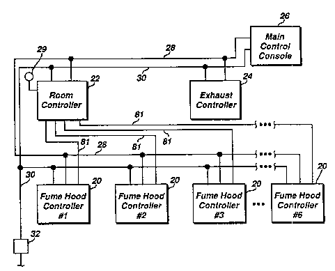
1 FIG. 1, a block diagram is shown of several fume hood
2 controllers 20 inteL.~ .eu~ed with a room controller 22, an
3 exhaust controller 24 that may be part of the room
4 controller itself and a main control con601e 26. The fume
5 hood controllers 20 are int~ d with the room
6 controller 22 and with the exhaust controller 24 and the
7 main control console 26 in a local area network illustrated
8 by line 28 which may be a multic~n~ tor cable or the like.
9 The room controller, the exhaust controller 24 and the main
10 control console 26 are typically part of the building main
11 HVAC system in which the laboratory rooms containing the
12 fume hood6 are located. The fume hood controllers 20 are
13 provided with power through line 30, which is at the proper
14 voltage via a transformer 32 or the like.
Referring to FIG. 2, a fume hood controller 20 is
16 illustrated with its input and output connector ports being
17 identified, and the fume hood controller 20 is connected to
18 an operator panel 34. It should be understood that each
19 fume hood will have a fume hood controller 20 and that an
operator panel will be provided with each fume hood con-
21 troller. The operator panel 34 is provided for each of the
22 fume hoods and it is inte, ~:o~l--e~;~ed with the fume hood
23 controller 20 by a line 36 which preferably comprises a
24 multi ~ du. Lor cable having eight conductors. The
operator panel has a connector 38, such as a 6 wire R,Jlll
26 type telephone jack for example, into which a lap top
27 personal computer or the like may be connected for the
28 purpose of inputting information relating to the
29 configuration or operation of the fume hood during initial
installation, or to change certain operating parameters if
31 n~c~Cc~ry, The operator panel 34 is preferably mounted to
32 the fume hood in a convenient location adapted to be easily
33 observed by a person who is working with the fume hood.
34 The fume hood controller operator panel 34
includes a liquid crystal display 40 which when selectively
36 activated provides the visual indication of various aspects
37 of the operation of the fume hood, including three digits
38 42 which provide the average face velocity. The display 40
203~2~8
--7--
1 illustrates other conditions such as low face velocity,
2 high face velocity and : ~n~ y condition and an
3 indication of controller failure. The operator panel may
4 have an alarm 44, an ~ ;y purge pushbutton 46 which an
operator can press to purge the fume hood in the event of
6 an accident. The operator panel has two ~llYiliAry switches
7 48 which can be used for various customer needs, including
8 day~night modes of operation. It is contemplated that
9 night time mode of operation would have a different and
preferably reduced average face velocity, presumably
11 because no one would be working in the area and such a
12 lower average face velocity would conserve energy. An
13 alarm silence switch 50 is also preferably provided.
14 Fume hoods come in ~nany different styles, sizes
and configurations, including those which have a single
16 sash door or a number of sash doors, with the sash ~oors
17 being moveable vertically, horizontally or in both direc-
18 tions. Additionally, various fume hoods have different
19 amounts of by-pass flow, i.e., the amount of flow per-
mitting opening that exists even when all of the sash ~oors
21 are as completely closed as their de6ign permits.
22 Referring to FIG. 3, there is shown a fume hood,
23 indicated generally at 60, which has a vertically operated
24 sash door 62 which can be moved to gain access to the fume
hood and which can be moved to the substantially closed
26 position as shown. Some types of fume hoods have a bypass
27 opening that is located above the door sash while others
28 are below the same. In some fume hoods, the first amount
29 of v~ ~ of a sash door will increase the opening at the
bottom of the door shown in FIG. 3, for example, but as the
31 door is raised, it will merely cut off the bypass opening
32 so that the effective size of the total opening of the fume
33 hood is maintained relatively constant for perhaps the
34 first one-fourth amount of movement of the sash door 62
through its course of travel.
36 Other types of fume hoods may include several
37 horizontally moveable sash doors 66 such as shown in FIGS.
38 4 and 5, with the doors being movable in upper and lower
2~2~8
--8--
1 pairs of adjacent tracks 68. When the doors are po6itioned
2 as shown in FIGS. 4 and 5, the fume hood opening i5
3 completely closed and an operator may move the doors in the
4 horizontal direction to gain acces~ to the fume hood. Both
5 of the fumes hoods 60 and 64 have an exhaust duct 70 ~,rhich
6 generally extends to an exhaust system which may be that of
7 the HVAC apparatus previously described. The fume hood 64
8 also includes a filtering ~LUULUL-: shown diayL ~ically
9 at 72 which filtering structure is intended to keep noxious
10 fumes and other contaminants from exiting the fume hood
11 into the exhaust sy6tem. Referring to FIG. 6, there is
12 shown a combination fume hood which has horizon~ally
13 movable doors 76 which are similar to the doors 66, with
14 the fume hood 74 having a frame structure 78 which ca]~ries
15 the doors 76 in suitable tracks and the frame structu~e 78
16 is also vertically movable in the opening of the fume hood.
17 The illu6tration of FIG. 6 ha6 portions removed
18 a6 s~own by the break lines 73 which is intended to
19 illustrate that the height of the fume hood may be greater
than is otherwise shown so that the frame structure 78 may
21 be raised sufficiently to permit adeqiuate access to the
22 interior of the fume hood by a person. There is generally
23 a by-pass area which is identified as the vertical area 75,
24 and there is typically a top lip portion 77 which mziy be
approximately 2 inches wide. This dimension is preferably
26 defined so that its effect on the calculation of the open
27 face area can be taken into consideration.
28 While not specifically illustrated, other
29 combinations are also possible, including multiple sets of
vertically moveable sash doors positioned adjacent one
31 another along the width of the fume hood opening, with two
32 or more sash doors being vertically moveable in adj~icent
33 tracks, much the same as residential c 1~ L windows
34 The fume hood controller is adapted to control
virtually any of the various kinds and styles of fume hoods
36 that are commercially available, and to this end, it hias a
37 number of input and output ports (lines, connectors or
38 connections, all considered to be equivalent for the
_ _ _ _ , .. , . . . . . . _ . . _ _ . . , _ _ _ _ _ _ _ _ _ _
2~5~8
. ~
g
1 ~.L~oses of describing the present invention) that can be
2 connected to various sensors that may be used wit~ the
3 controller. As shown in FIG. 2, there are five sash
4 position sensor ports for use in sensing the position of
both horizontally and vertically moveable sashes.
6 To determine the position of the sash doors, a
7 sash position sensing means embodying the present invention
8 is provided adj acent each movable sash door and is
9 generally illustrated in FIGS. 7, 8 and 9. Referring to
FIG. 8, the door sash position sensing means comprises an
11 elongated switch - -hAn; Fm 80 of relatively simple
12 mechanical design which preferably consists of a relatively
13 thin polyester base layer 82 upon which is printed a strip
14 of electrically resistive ink 84 of a known constant
resistance per unit length. Another polyester base layer
16 86 is provided and it has a strip of electrically
17 conductive ink 88 printed on it. The two base layers 82
18 and 86 are adhesively bonded to one another by two beads of
19 adhesive 90 located on opposite sides of the strip. The
base layers are preferably approximately five-thousandths
21 of an inch thick and the beads are approximately two-
22 thousandths of an inch thick, with the beads providing a
23 spaced area between the conductive and resistive layers 88
24 and 84. The switching - ^hAn;~m 80 is preferably applied
to the fume hood by a layer of adhesive 92.
26 The polyester material is sufficiently flexible
27 to enable one layer to be moved toward the other so that
28 contact is made in L~ OI-S~ to a preferably spring biased
29 actuator 94 carried by the appropriate sash door to which
the strip is placed adjacent to so that when the sash door
31 is moved, the actuator 94 moves along the switching
32 r ' -n;'!~ 80 and provides contact between the resistive and
33 conductive layers which are then sensed by electrical
34 circuitry to be described which provides a voltage output
that i5 indicative of the position of the actuator 94 along
36 the length of the switching means. Stated in other words,
37 the actuator 94 is carried by the door and therefore
38 provides an electrical voltage that is indicative of the
-lO- 205~2~8
1 position of the sash door.
2 The actuator 94 is preferably spring biased
3 toward the switching -- An;F~ 80 so that as the door is
4 moved, sufficient ~L-::a-uL-z i5 applied to the switching
means to bring the two base layers together so that the
6 resistive and conductive layers make electrical contact
7 with one another and if this is done, the voltage level is
8 provided. By having the switching means 80 of sufficient
9 length so that the full extent of the travel of the sash
door is provided as shown in FIG. 3, then an accurate
11 deter~ination of the absolute sash position can be made.
12 It should be understood that the illustration of
13 the switching ---hAniF~ 80 in FIGS. 3 and 5 is intended to
14 be diagrammatic, in that the switching r--hAn; cm is
preferably actually located within the sash frame itself
16 and accordingly would not be visible as shown. The width
17 and thickness dimensions of the switching me~-hAn; cm are so
18 small that interference with the operation of the sash door
19 is virtually no problem. The actuator 94 can also be
placed in a small hole that may be drilled in the sash door
21 or it may be attached externally at one end thereof so that
22 it can be in position to operate the switch 80. In the
23 vertical moveable sash doors shown in FIGS. 3 and 6, a
24 switching ---hAniF"` 80 is preferably provided in one or the
other of the sides of the sash frame, whereas in the fume
26 hoods having horizontally movable doors, it is preferred
27 that the switching r- ' AniF~ 80 be placed in the top of the
28 tracks 68 so that the weight of the movable doors do not
29 operate the switching m~-hAni cm 80 or otherwise damage the
same. It is also preferred that the actuator 94 be located
31 at one end of each of the doors for reasons that are
32 de6cribed in the cross-referenced application entitled A
33 method and apparatus for detf~rmin;nJ the uncovered size of
34 an opening adapted to be covered by multiple moveable doors
by Ahmed et al., Serial No. 2 055,147
36 Turning to FIG. 9, the preferred electrical
37 circuitry which generates the position indicating voltage
38 is illustrated, and this circuitry is adapted to pro~ide
,
~a~258
--11--
1 two separate voltages indicating the position of two sash
2 doors in a single track. With respect to the cro6s-section
3 shown in FIG. 5, there are two horizontal tracks, each of
4 which carries two sash doors and a switching -- -nl~-- 80
is provided for each of the tracks as is a circuit as shown
6 in FIG. 9, thereby providing a distinct voltage for each of
7 the four sash doors as shown.
8 The switching ~eans is preferAbly applied to the
9 fume hood with a layer of adhesive 92 and the actuator 94
is adapted to bear upon the switching means at locations
11 along the length thereof. Referring to FIG. 7, a
12 diagrammatic illustration of a pair of switching meams is
13 illustrated such as may occur with respect to the two
14 tracks shown in FIG. 5. A switching --- ~niFm 80 is
provided with each track and the four arrows illustrated
16 represent the point of contact created by the actuators 94
17 which result in a signal being applied on each of the ends
18 of each switching means, with the magnitude of the signal
19 representing a voltage that is proportional to the distance
between the end and the nearest arrow. Thus, a single
21 switching ~ ni s-n 80 is adapted to provide position
22 indicating signals for two doors located in each track.
23 The circuitry that is used to accomplish the voltage
24 generation is shown in FIG. 9 and includes one of these
circuits for each track. The resistive element is shown at
26 84 and the conductive element 88 is also illustrated l~eing
27 connected to ground with two arrows being illustrated, and
28 re~, ese.l~ed the point of contact between the resistive and
29 conductive elements caused by each of the actuators 94
associated with the two separate doors. The circuitry
31 includes an operational amplifier 100 which has its output
32 connected to the base of a PNP transistor 102, the emitter
33 of which is connected to a source of positive voltage
34 through resistor 104 into the negative input of the
operational amplifier, the positive input of which is also
36 conn~cte~fl to a source of positive voltage of prefe~-ably
37 approximately five ~rolts. The collector of the transistor
38 102 is connected to one end of the resistive element 84 and
. 20~258
--12--
1 has an output line 106 on which the voltage i8 produced
2 that is indicative of the position of the door.
3 The circuit operates to provide a constant
4 current directed into the resistive element 84 and this
current results in a voltage on line 106 that is
6 proportional to the resistance value between the collector
7 and ground which changes ~s the nearest point of contact
8 along the resistance changes. The operational amplifier
9 operates to attempt to drive the negative input to equal
the voltage level on the positive input and this results in
11 the current applied at the output of the operational
12 amplifier varying in direct proportion to the effective
13 length of the resistance strip 84. The lower portion of
14 the circuitry operates the same way as that which has been
described and it similarly produces a voltage on an output
16 line 108 that is proportional to the distance between the
17 connected end of the resistance element 84 and the point of
18 contact that is made by the actuator 94 associated with the
19 other sash door in the track.
Prom the foregoing description, an; L~v~d
21 sensing means for det~nminin~J the position of sash doors is
22 provided that offers advantages over the prior art. Even
23 though one switching means 80 is provided for each track,
24 the unique circuitry enables position indicating voltages
for two 6ash doors that are moveable in a single set of
26 tracks to be produced. The apparatus is simple to install
27 and generates the signals utilizing a minimum of ~ .t s
28 which contributes to its rcxLL~ -ly good cost effectiveness
29 in terms of its manufacture.
While various embodiments of the present inven-
31 tion have been shown and described, it should be understood
32 that various alternatives, substitutions and equivalents
33 can be used, and the present invention should only be
34 limited by the claims and equivalents thereof.
Various features of the present invention are set
36 forth in the following claims.