Language selection

Search

Patent 2055369 Summary

Third-party information liability

Some of the information on this Web page has been provided by external sources. The Government of Canada is not responsible for the accuracy, reliability or currency of the information supplied by external sources. Users wishing to rely upon this information should consult directly with the source of the information. Content provided by external sources is not subject to official languages, privacy and accessibility requirements.

Claims and Abstract availability

Any discrepancies in the text and image of the Claims and Abstract are due to differing posting times. Text of the Claims and Abstract are posted:

  • At the time the application is open to public inspection;
  • At the time of issue of the patent (grant).
(12) Patent Application: (11) CA 2055369
(54) English Title: MIXING APPARATUS
(54) French Title: APPAREIL SERVANT A MELANGER
Status: Deemed Abandoned and Beyond the Period of Reinstatement - Pending Response to Notice of Disregarded Communication
Bibliographic Data
(51) International Patent Classification (IPC):
(72) Inventors :
  • ROUECHE, W. R. (Canada)
  • VAN HUMBECK, THOMAS (Canada)
(73) Owners :
  • W. R. ROUECHE
  • THOMAS VAN HUMBECK
  • DEW ENGINEERING AND DEVELOPMENT LIMITED
(71) Applicants :
  • W. R. ROUECHE (Canada)
  • THOMAS VAN HUMBECK (Canada)
  • DEW ENGINEERING AND DEVELOPMENT LIMITED (Canada)
(74) Agent:
(74) Associate agent:
(45) Issued:
(22) Filed Date: 1991-11-13
(41) Open to Public Inspection: 1992-05-14
Examination requested: 1992-05-26
Availability of licence: N/A
Dedicated to the Public: N/A
(25) Language of filing: English

Patent Cooperation Treaty (PCT): No

(30) Application Priority Data:
Application No. Country/Territory Date
612,226 (United States of America) 1990-11-13

Abstracts

English Abstract


ABSTRACT OF THE DISCLOSURE
Conventional devices for mixing liquids include a
container and some form of stirrer for one stage mixing. A
two stage mixer for producing a homogeneous emulsion includes
a container, a stirrer, and a preliminary mixer in the form
of an arcuate plate defining a target above the stirrer. The
two liquids are injected into the container through orifices,
which are suitably oriented that the liquid streams converge
to meet at the target. Thus, preliminary mixing of the
liquids occurs at the target, and the liquids fall to the
bottom of the container where the mixing process is completed
by the stirrer.


Claims

Note: Claims are shown in the official language in which they were submitted.

THE EMBODIMENTS OF THE INVENTION IN WHICH AN
EXCLUSIVE PROPERTY OR PRIVILEGE IS CLAIMED ARE DEFINED AS
FOLLOWS.
1. An apparatus for mixing liquids comprising
container means defining a mixing chamber for receiving the
liquids; target means in said chamber; a plurality of discrete
inlet means for introducing liquids into said mixing chamber
at spaced apart locations proximate the upper end thereof,
said inlet means being adapted to spray the liquids into
contact with each other at said target means for substantially
simultaneous, overlapping impingement upon said target means
to initiate mixing of the liquids; and mixer means in said
chamber for completing the mixing of the liquids falling
beneath said target means.
2. An apparatus according to claim 1, wherein said
container means includes side wall means; and said target
means is arcuate plate means with a vertical axis of curvature
spaced apart from said side wall means in the area of said
inlet means, said inlet means being adapted to spray the
liquids against a curved portion of said plate means.
3. An apparatus according to claim 2, wherein said
side wall means is cylindrical, and said plate means is
U-shaped, the plate means being connected to said side wall
means on each side of said inlet means and curving inwardly
towards the center of the container means.
4. An apparatus according to claim 1, 2 or 3,
wherein said mixer means is a mechanical stirrer.

5. An apparatus according to claim 2, wherein said
inlet means includes a pair of nozzle means in said side wall
means, the longitudinal axes of said nozzle means intersecting
proximate one location on said target means, whereby to
promote mixing of liquids before and during impinging upon
said target means.
6. An apparatus according to claim 5, wherein said
plate means is generally U-shaped in cross section, said one
location being at the inner centre of the bight of the U.

Description

Note: Descriptions are shown in the official language in which they were submitted.


20~53~
This invention relates to a mixing apparatus, and in
particular ~o a two stage apparatus for continuously mixing
liquids to produce a homogeneous emulsion.
While the apparatus was designed specifically to
produce emulsions by mixing an aqueous slurry and an organic
solvent, it will be appreciated that the apparatus can be used
to mix other ingredients. By "liquids" is meant water,
organic solvents and slurries. For example, an aqueous slurry
and an organic slurry (an organic solvent with a suspended
solid) can be mixed using the apparatus of the present
invention.
In general, existing mixing devices are single stage
mixers including a stirrer. Often, such devices are not
sufficienkly efficient to produce homogeneous emulsions or at
least not in a reasonable period of time.
Searches in the patent literature disclose Canadian
Patents Nos. 536,106F which issued to J.A. Carver et al on
January 22, 1957 and 817~797, which issued to J.F. Gurley, Jr.
on July 15, 1969, and U.S. Patent No. 3,425,669, which issued
to P.G. Gaddis on February 4, 1969, which have elements in
common with the invention described herein. However, like the
conventional mixer described above, the patented devices are
single stage mixers relying, for example on somewhat
complicated stirrers to efect mixing. Moreover, existing
mixers for producing aqueous slurries usually include a large

2D~5369
tank for batch pxocessing of slurries, i.e. for preparing one
large batch of slurry at a time. The slurry is produced, the
tank is emptied and the process is repeated.
An object of the present invention is to solve the
problems of existing mixers by providing a relatively simple,
two stage mixing apparatus which can be used to produce a
homogeneous emulsion quickly.
Another object of the present invention is to
provide a two stage mixing apparatus, which can operate
continuously, and which therefore is relatively compact.
Accordingly, the present invention relates to an
apparatus fQr mixing liquids comprising container means
defining a mixing chamber for receiving the liquids; target
means in said chamber; a plurality of inlet means for
introducing liquids into said mixing chamber proximate the
upper end thereof, said inlet means being adapted to spray
the liquids into contact with each other for substantially
simultaneous, overlapping impingement upon said target means
to initiate mixing of the liquids; and mixer means in said
chamber for completing the mixing of the liquids falling
beneath said target means.
The invention will be described in greater detail
with reference to the accompanying drawing, which illustrates
a preferred embodiment of the invention, and wherein-
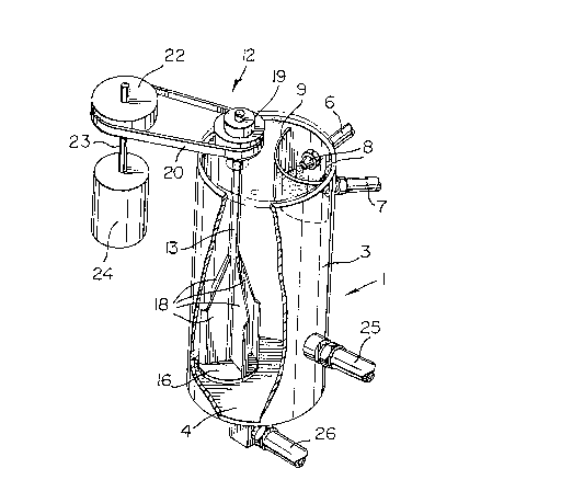
Figure 1 is a schemati~, partly sectioned, isometric
, ~, . . , I ~

2~5369
view of a mixing apparatus in accordance with the present
invention;
Figure 2 is a perspective view from below of a cover
used in the mixing apparatus o~ Fig.l; and
Figure 3 i5 a plan view of a container used in the
mixing apparatus of Fig. 1.
Wi~h reference to the drawing, the mixing apparatus
of the present invention include~ a container generally
indicated at 1 and a cover 2 for closing the top end thereof.
The container 1 is defined by a cylindrical side wall 3 and a
Gircular bottom wall 4. The cover 2, the side wall 3 and the
bottom wall 4 define a mixing chamber for receiving an organic
solvent and a slurry. The solvent and the slurry are
introduced into the mixing chamber via a pair of inlet pipes 6
and 7, and nozzles 8 mounted in the side wall 3.
A taryet in the form of an arcuate plate 9 is
mounted in the container 1. The plate 9 is generally
U-shaped in cross section, or when viewed from above or below. ~;
~ The ends of the plate 9 are welded to the side wall 3
extending around the nozzles 8~ The nozzles 8 and the
orifices therein (not shown) are oriented in such a manner
that their longitudinal axes and those of the streams 10 and
11 (Fig. 3) of liquid sprayed into the chamber intersect at
the inner surface of the bight of the U defined by the plate
lQ, i.e. at the location where the two liquid streams impinge
upon the plate 9. The impingement of overlapping streams of

2t~5~36~
liquid before and upon contacting the plate 9 results in first
stage or initial mixing of the liquids. As best shown in
Fig. 3, the streams 10 and 11 come into contact with each
other before reaching the plate 9, and mixing begins
immediately.
The thus mixed liquids fall to the bottom of the
container for second stage mixing, which is effected by a
stirrer generally indicated at 12. The stirrer 12 includes a
shaft 13 rotatably mounted in a sleeve 14 (Fig. 2~ extending
downwardly from the circular plate 15 defining the cover 2.
The shaft 13 carries a circular bottom plate 16 and a
plurality of radially extending blades or vanes 18 on the
plate 16. A pulley 19 is mounted on the top end of the shaft
13 above the cover 2. The pulley 19 is rotated by a belt 20
and a second, larger pulley 22, which is mounted on the shaft
23 of a motor 24.
The emulsion produced in the container i5 discharged
therefrom via an outlet pipe 25 in the side wall 3 near the
bottom end of the container. During normal operation, with
the lid 2 secured to the top of the container 1, the liquids
are injected under pressure~ Thus, the mixing process is
carried out under pressure, whereby relatively small volumes
of liquid are continuously mixed and discharged from the
container 1 through the pipe 25. A drain 26 is provided in the
bottom wall 4 for emptying the container.

2~553~
Thus~ there has been described a relatively simple
mixing apparatus for effective two stage mixing, the first
stage occurring when two liquids are injected into the
container 1 under preqsure and impinging on the plate 9
defining the target, and the second stage involving stirring
with the stirrer 11.

Representative Drawing
A single figure which represents the drawing illustrating the invention.
Administrative Status

2024-08-01:As part of the Next Generation Patents (NGP) transition, the Canadian Patents Database (CPD) now contains a more detailed Event History, which replicates the Event Log of our new back-office solution.

Please note that "Inactive:" events refers to events no longer in use in our new back-office solution.

For a clearer understanding of the status of the application/patent presented on this page, the site Disclaimer , as well as the definitions for Patent , Event History , Maintenance Fee  and Payment History  should be consulted.

Event History

Description Date
Inactive: IPC expired 2022-01-01
Revocation of Agent Requirements Determined Compliant 2020-09-01
Inactive: IPC from MCD 2006-03-11
Inactive: Inventor deleted 2002-09-18
Application Not Reinstated by Deadline 1996-05-13
Time Limit for Reversal Expired 1996-05-13
Inactive: Adhoc Request Documented 1995-11-13
Deemed Abandoned - Failure to Respond to Maintenance Fee Notice 1995-11-13
Request for Examination Requirements Determined Compliant 1992-05-26
All Requirements for Examination Determined Compliant 1992-05-26
Application Published (Open to Public Inspection) 1992-05-14

Abandonment History

Abandonment Date Reason Reinstatement Date
1995-11-13
Owners on Record

Note: Records showing the ownership history in alphabetical order.

Current Owners on Record
W. R. ROUECHE
THOMAS VAN HUMBECK
DEW ENGINEERING AND DEVELOPMENT LIMITED
Past Owners on Record
None
Past Owners that do not appear in the "Owners on Record" listing will appear in other documentation within the application.
Documents

To view selected files, please enter reCAPTCHA code :


To view images, click a link in the Document Description column. To download the documents, select one or more checkboxes in the first column and then click the "Download Selected in PDF format (Zip Archive)" or the "Download Selected as Single PDF" button.

List of published and non-published patent-specific documents on the CPD .

If you have any difficulty accessing content, you can call the Client Service Centre at 1-866-997-1936 or send them an e-mail at CIPO Client Service Centre.


Document
Description 
Date
(yyyy-mm-dd) 
Number of pages   Size of Image (KB) 
Abstract 1992-05-13 1 29
Claims 1992-05-13 2 61
Drawings 1992-05-13 1 46
Descriptions 1992-05-13 5 176
Representative drawing 1999-03-04 1 23
Fees 1994-10-24 1 37
Fees 1993-09-21 1 29