Language selection

Search

Patent 2055509 Summary

Third-party information liability

Some of the information on this Web page has been provided by external sources. The Government of Canada is not responsible for the accuracy, reliability or currency of the information supplied by external sources. Users wishing to rely upon this information should consult directly with the source of the information. Content provided by external sources is not subject to official languages, privacy and accessibility requirements.

Claims and Abstract availability

Any discrepancies in the text and image of the Claims and Abstract are due to differing posting times. Text of the Claims and Abstract are posted:

  • At the time the application is open to public inspection;
  • At the time of issue of the patent (grant).
(12) Patent Application: (11) CA 2055509
(54) English Title: MOTOR VEHICLE SPEED LOGGER
(54) French Title: APPAREIL D'ENREGISTREMENT DE LA VITESSE D'UN VEHICULE AUTOMOBILE
Status: Deemed Abandoned and Beyond the Period of Reinstatement - Pending Response to Notice of Disregarded Communication
Bibliographic Data
Abstracts

English Abstract


ABSTRACT
An electronic computing apparatus which upon being installed
in an motor vehicle, acquires and accumulates the velocity
of the vehicle. This velocity data forms the vehicles'
MAXIMUM SPEED HISTORY and would be used to prove maximum
velocities the vehicle had attained. Upon request via a
keyboard which is part of the apparatus, the velocity data
may be printed to an attached paper printing device. (The
appartus may become a legal measuring and storage device for
motor vehicles.) The apparatus would be sealed against
tampering.


Claims

Note: Claims are shown in the official language in which they were submitted.

CLAIMS
The embodiments of the invention in which an exclusive property or privilege is claimed are defined as follows:
1. An electronic apparatus installed in the motor vehicle, to sense and continually record the velocity of a
motor vehicle.
2. An electronic apparatus which will print, display, and/or transfer to a secured memory device, the
recorded vehicle speed information, of the motor vehicle in which the apparatus is installed.
3. An electronic apparatus which records vehicle velocity and stores this velocity data along with a real-time
stamp into non-volatile electronic memory.

Description

Note: Descriptions are shown in the official language in which they were submitted.


zc~ss~9
SPECIFICATION
This invention relales lo an eleclronic compulin~ appatalus for lhe use in a molor vehicle Ihal which records the
vehicles` velocity Into eleclronlc memory.
The method of measuring a motor vehicles velocity~ is by ei~her a mechanical or electronic melhod and is
displayed on an instrument commonly known as a spccdomeler. An associated ins~rument whlch permanen~ly
measures and records lolal dislance Itavolled by Ihe vehicle is commonly known as an odomeler. The
speedometer is merely an inslantaneous measuring inslrumenl and d<~es nol record any previous velocities which
Ihe molor vehicle may have had allained. There comes siluallons where knowing Ihe hlslory of a molor vehicles
velocities would become useful. One example is heing accused Ihat lhe molot vehicle in question had been
movin~ at a particular velocity monitored by a police officers radar gun which may in fact be false. The police
radar may have picked up anolher moving objecl or vehicle. The driwr of Ihe molor vehicb has no molhod or
proving what velocity with wh~ch the motor vehicle was moving. Also if unmanned photo radar is used the
vehicle in question does not have evidence at w~th what velocity the vehicle was moving at. The second example is
a motor vehicle fleel ownet may experience significant motor vehicle fuel consumption but does not know at what
velocities fleet drivers drive the vehicles at since driving faster increases fucl consumption. If the neet owner can
attain knowledge of his fleet vehicles velocities then costs may be beller controlled and warn drivers to slow
down.
A method which we found to solve this problem of not knowing the molor vehicles velocity hislory was to design
an electronic apparalus which would sense and store electronically the velocities with which the molor vehicle is
moving at. Upon installation of this apparatus it would continualb store the vehicles velocities and that the
stored velocity history data would be available to be retrieved when it is deemed nesessary. This vehicle velocity
information may now then prove the velocities with which the motor vehicb was moving at in tbe recent pasu The
vehicle owner now has evidence lo prove otherwise what the police radar. police pace or photo radar had claimed.
The motor vehicle neet owner as well may now log his or her vehicles velocities along with distances travelled.
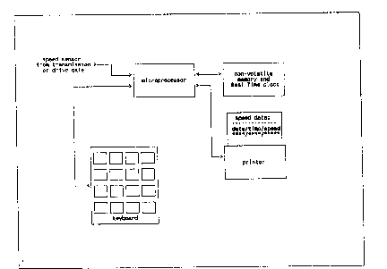
Itl the drawingwhich illustrates the embodiments of Ihe invention
Figure I is a block diagtam of this embodiment.
The apparatus contains a microyrocessor the relaled software and n(M-volatile memory to which to store motor
vehicle velosity data and a printing device to physically record vehicle velocity history when required. A keyboatd
is used to enter the date and time of an event of which the vehicle velocities of a defined time proximity of the
event are requested to be printed.
Asensing device of inductive or optical in nature instaUed in the veh~cle is used to translate Ihe rolational rate of
the transmission output shaft or drive axle ioto an eleclrical signal. Most newer motor vehicles contain a speed
sensor instaUed at the motor veh~cles manufacturing factory. This sensing device may be used by the motor
vehicle manufacturer for the cruise control or anti-lock brakes or not used. Therefore this factory wouW be an
ideal source for sensing vehicle velosity. If the vehicle is older and does not contain a factory SPEED SENSOR a
sensing device would be externally mounted beside the drive axle of the vehicle with clearance to the rotating
drive axle. A permanently magnedc device would be installed onto the drive axle that would activate the speed
sensor upon each re~ olution.
The apparatus monitors the induced voltage potential produced from the speed sensor and filters it to obtain a
stabb signal. The apparatus calculates velocity derived from the speed sensor by entering the frequency of its
activation iDto an equation relevant for that type of vehicle. This speed is then saved into memory. Each vehicb
typewould require individual calibration as to compensate for tire size and axle ratios.
A time~ut counter is started upon vehicle motion which is a pre-determined value (e.g. 30 seconds) and the
maximum instantancous velocity atlained within that lime-out is stored in RAM (Random Access Memory).
Upon expiration of Ihis time-out the maximum velosity is stored into the uon-volatile static RAM and given a
Real Time (the current date and time) stamp of that instant which is also stored. The time-out counter is then
reset and the process continues again. The successive periods of vehicle velocities are stored in successive non-
vohtile memory locations~ along with their individual Real Time stamp. Vehicle velocity data collection continues
indefinitely once the device is installed in a vehicle.
The apparatus would store the vehicle velocity data for in a circular buffer rashion of a maximum pre-determined
duration of time (e.g. 2 weeks I month or several months). The circular bu~fer simply implies that the current
velocity data is kept at the end of the non-volatib memQq and keeps a history of past velocities. As new velocity
data is stored it is written over ~he oldest data in the non-volatile memory. The duration of retaining the acquired
speed data would be restricted by the amount of available memory cost of Ihe device and algorilhm used to store
the speed data.

~;5S09
When the veloci~ies of an even~ ate desired ~o ho rclr~eved onlo a prlnl~n6 devh:c the dale and llme of lhe cvent is
en~ercd in~o ~he keyboard. and the memory is lhen s~lrched for lhc approprlale da~a. If Ihc dl~a is no~ round for
~hal lime even~ an error is indicalcd requesling lor corrccl inl~rmaîlon. Once Ihe veloclly dalu is found il is
primed onlo ~he altached prln~lng devlcc~ accompanied by lhe dale and llme of ~hal evcnt. Includcd in the
prin~out are speeds of a pre-determined lime before ~he evcnl and ~he speeds of a prc-dc~crmined ~ime af~er lhc
evenl (e~g~ lS minu~es before and IS mlnu~es aher lhe even~ ~herefore a ~o~al of 30 minu~e proximily of lhC evenl).
This ~ime span of the vehicles speed would allow ror any discrepancy of lime difference bc~wccn ~he recorded
speed da~a and whom is questioning it~ This veloci~y data printout would serve as evidence ~o any queslioned
vchicle velocities~ Tbe veloc~ty data may also be transferred to a secured non-volatib mcmory devicc such as a
memory card to be used as evidence and that lhe stored velocity data bc prlnted or displaycd cxternal ~o thc motor
vehicle at an official loca~iom
The current time and date are obtained from a Real Time Clock embeddcd as parl of the non-volalile slalic RAM
device which is also used lo Slore lhe vehicle veloci~y da~a~
Each apparatus when installed in a motor vehicle would have its own distinct serial numben This serial number
along with the vehicle scrlal number wouîd be printcd onto the printing devicc when the velocities of the motor
vebicle are requcstcd.
Tbe printing device would be thermal in nature using thermal paper and would therefore alleviate any nced for
printer ink ribbons.

Representative Drawing
A single figure which represents the drawing illustrating the invention.
Administrative Status

2024-08-01:As part of the Next Generation Patents (NGP) transition, the Canadian Patents Database (CPD) now contains a more detailed Event History, which replicates the Event Log of our new back-office solution.

Please note that "Inactive:" events refers to events no longer in use in our new back-office solution.

For a clearer understanding of the status of the application/patent presented on this page, the site Disclaimer , as well as the definitions for Patent , Event History , Maintenance Fee  and Payment History  should be consulted.

Event History

Description Date
Time Limit for Reversal Expired 1996-05-13
Application Not Reinstated by Deadline 1996-05-13
Deemed Abandoned - Failure to Respond to Maintenance Fee Notice 1995-11-13
Inactive: Adhoc Request Documented 1995-11-13
Application Published (Open to Public Inspection) 1993-05-14

Abandonment History

Abandonment Date Reason Reinstatement Date
1995-11-13
Owners on Record

Note: Records showing the ownership history in alphabetical order.

Current Owners on Record
TAPIO OLAVI VAHAMAKI
Past Owners on Record
None
Past Owners that do not appear in the "Owners on Record" listing will appear in other documentation within the application.
Documents

To view selected files, please enter reCAPTCHA code :


To view images, click a link in the Document Description column. To download the documents, select one or more checkboxes in the first column and then click the "Download Selected in PDF format (Zip Archive)" or the "Download Selected as Single PDF" button.

List of published and non-published patent-specific documents on the CPD .

If you have any difficulty accessing content, you can call the Client Service Centre at 1-866-997-1936 or send them an e-mail at CIPO Client Service Centre.


Document
Description 
Date
(yyyy-mm-dd) 
Number of pages   Size of Image (KB) 
Abstract 1993-05-14 1 12
Cover Page 1993-05-14 1 11
Claims 1993-05-14 1 11
Drawings 1993-05-14 1 9
Descriptions 1993-05-14 2 117
Representative drawing 1999-06-02 1 8
Fees 1993-12-09 1 21
Fees 1992-11-13 1 19