Language selection

Search

Patent 2055626 Summary

Third-party information liability

Some of the information on this Web page has been provided by external sources. The Government of Canada is not responsible for the accuracy, reliability or currency of the information supplied by external sources. Users wishing to rely upon this information should consult directly with the source of the information. Content provided by external sources is not subject to official languages, privacy and accessibility requirements.

Claims and Abstract availability

Any discrepancies in the text and image of the Claims and Abstract are due to differing posting times. Text of the Claims and Abstract are posted:

  • At the time the application is open to public inspection;
  • At the time of issue of the patent (grant).
(12) Patent Application: (11) CA 2055626
(54) English Title: FLOATING RING GEAR AND DIFFERENTIAL GEAR ASSEMBLY
(54) French Title: ENSEMBLE D'ENGRENAGE DIFFERENTIEL ET D'ANNEAU DANSANT
Status: Deemed Abandoned and Beyond the Period of Reinstatement - Pending Response to Notice of Disregarded Communication
Bibliographic Data
(51) International Patent Classification (IPC):
  • F16H 55/17 (2006.01)
  • B60K 17/16 (2006.01)
  • F16H 48/08 (2006.01)
(72) Inventors :
  • LONG, JAMES R. (United States of America)
(73) Owners :
  • EATON CORPORATION
(71) Applicants :
  • EATON CORPORATION (United States of America)
(74) Agent: BORDEN LADNER GERVAIS LLP
(74) Associate agent:
(45) Issued:
(22) Filed Date: 1991-11-15
(41) Open to Public Inspection: 1992-06-06
Examination requested: 1993-11-19
Availability of licence: N/A
Dedicated to the Public: N/A
(25) Language of filing: English

Patent Cooperation Treaty (PCT): No

(30) Application Priority Data:
Application No. Country/Territory Date
624,844 (United States of America) 1990-12-05

Abstracts

English Abstract


ABSTRACT OF THE DISCLOSURE
A ring gear (50) is provided with a plurality of
substantially evenly circumferentially spaced posts (10)
that extend radially inwardly and are adapted to carry
rotary differential pinion gears (12) whose teeth are
adapted to meshingly engage the teeth of side gears (18)
and (18') respectively secured to the ends of axially
aligned spaced-
apart axle shafts (20) and (20') to provide a motor
vehicle differential gear assembly (100) that enables ring
gear (50) to float relative axle shafts (20) and (20') in
the space therebetween.


Claims

Note: Claims are shown in the official language in which they were submitted.

-7-
THE EMBODIMENTS OF THE INVENTION IN WHICH AND EXCLUSIVE
PROPERTY OR PRIVILEGE IS CLAIMED ARE DEFINED AS FOLLOWS:
1. A vehicular differential gear assembly (100) for
transferring rotational torque between a pinion gear (16)
rotatably driven by a driver member (14) and a pair of
substantially axially aligned spaced-apart rotary driven
members (20,20') that are respectively journaled for
rotation and have a central rotational axis (C2)
disposed in substantial perpendicular relationship to the
pinion gear central rotational axis (C1) and have a side
gear (18,18') secured respectively thereto having their
teeth in facing relationship to each other across the
space between the driven members, (20,20') said assembly
(100) comprising:
a ring gear (50) disposed in the space between the
side gears, said ring gear having an annular configuration
defined between an inner periphery and an outer periphery
thereof and having a central rotational axis (C1) in
substantial perpendicular relationship to the pinion gear
central rotational axis, said ring gear (50) having a
plurality of substantially equi-circumferentially spaced
teeth (8) that are disposed between the inner and outer
periphery thereof and face towards one of the side gears
(18,18') and are meshingly engagable with the pinion gear
teeth so as to enable the ring gear to be rotatably driven
thereby, and said ring gear having at least two
equi-circumferentially spaced posts (10) extending
radially inwardly from the inner periphery thereof;
a differential pinion gear (12) mounted on each post
(10), each of said gears having diametrically opposed
teeth that simultaneously meshingly engage the teeth of
both side gears (18,18') and are adapted in combination
therewith to provide support for the ring gear and enable
the ring gear to float as the differential pinion gears
(12) rotate the side gears in response to rotation of the
ring gear (50) by the pinion gear (16).

-8-
2. A ring gear (50) for transferring rotational torque
between a pinion gear (16) rotatably driven by a vehicular
driver member (14) and a pair of substantially axially
aligned spaced-apart rotary driven members (20,20') that
are respectively journaled for rotation and have a central
rotational axis (C2) disposed in substantial
perpendicular relationship to the pinion gear central
rotational axis (C1) and have a side gear (18,18')
secured respectively thereto having their teeth in facing
relationship to each other across the space between the
driven members (20,20'), said ring gear (50) adapted to be
disposed in the space between the side gears (18,18') and
having an annular configuration defined between an inner
periphery and an outer periphery thereof and having a
plurality of substantially equi-circumferentially spaced
teeth (8) that are disposed between the inner and outer
periphery thereof and are adapted to face towards one of
the side gears (18,18') and to meshingly engage with the
pinion gear teeth so as to enable the ring gear to be
rotatably driven thereby, and said ring gear (50) having
at least two equi-circumferentially spaced posts (10)
extending radially inwardly from the inner periphery
thereof, said posts adapted to respectively carry a
differential pinion gear (12) mounted thereon having
diametrically opposed teeth that are adapted
simultaneously to meshingly engage the teeth of both side
gears and, in combination therewith, to provide support
for the ring gear and enable the ring gear to float as the
differential pinion gears (12) rotate the side gears
(18,18') in response to rotation of the ring gear (50) by
the pinion gear (16).
3. The assembly (100) of claim 1 wherein the ring gear
(50) has four of the posts (10) that extend radially
inwardly from the inner periphery thereof and respectively
have the differential pinion gear (12) mounted thereon.

- 9 -
4. The assembly (100) of claim 1 wherein the ring gear
teeth are spiral bevel teeth.
5. The assembly (100) of claim 1 wherein the ring gear
teeth are hypoid teeth.
6. The ring gear (50) of claim 2 having four of the posts
(10) that extend radially inwardly from the inner
periphery thereof for mounting the differential pinion
gear (12) mounted thereon.
7. The ring gear (50) of claim 2 wherein the ring gear
teeth are spiral bevel teeth.
8. The ring gear (50) of claim 2 wherein the ring gear
teeth are hypoid teeth.

Description

Note: Descriptions are shown in the official language in which they were submitted.


~9-A&~-2~6
~OATIN~ RI~G ~AR A~D DI~FER~TIAL G~AR ~SSE~BLY
INT~ODUCTION
This invention relates generally to a vehicular
differential ring gear and gear assembly for transferring
05 rotational torque between a rotary driver member such as a
pinion gear driven by the output shaft of a change gear
transmission and a pair of rotary driven members such as
paired wheel axle shafts and more particularly to a ring
gear and a differential gear assembly using a ring gear
that is adapted to be supported by differential pinion
gears meshed with side gears respectively rotatably
supported in an axle housing and adapted to b~ secured to
the wheel axle shafts and to float relative thereto as the
side gears are caused to rotate in response to rotation of
the ring gear.
sAc~GRou~D OF T~E INVE~TION
Ring gears have been used for many years in motor
vehicle differer,tial gear assemblies to transfer
rotational torque between a rotary driver member such as
the output shaft of a change gear transmission and a pair
of rotary driven members such as a pair of substantially
axially aligned spaced-apart axle shafts journaled for
rotation and having a wheel mounted on their respective
outboard ends.
Examples of various types of prior art type motor
vehicle differential gear assemblies are disclosed in
~nited States Patents 2,241,606; 3,000,456; and 3,38~,760,
the disclosures of which are incorporated herein by
reference and the latter two of which are assigned to the
assignee of the present invention.

~ 3
--2--
Such prior art type differential gear assemblies
however employ a great number of costly components in
addition to requiring a large differential housing to
protect the numerous components as well as requiring
05 precise alignment between the ring gear and the
differential housing and between the differential pinion
gears and the side gears as hereinafter described in more
detail with respect to the prior art differential gear
assembly in FIGURE 1.
SVM~ARY OF THE INVENTION
Accordingly, it is an object of this invention to
provide a ring gear for use with a motor vehicle
differential gear assembly that is adapted fo float
relative a pair of side gears secured to driven members
being rotated by the ring gear.
It is another object of this invention to provide a
ring gear and a motor vehicle differential gear assembly
using a ring gear that is simple and economical to
manufacture and that advantageously reduces the number of
components heretofore used in vehicle differentials
employing ring gears in addition to being adapted to float
relative the differential housing and the side gears
secured to the driven members and thus lessen the precise
alignment heretofor required for the ring gear.
B~I~F ~SCRIPTION ~F THE DRAWI~S
FIGURE l is a central cross-sectional side view of a
prior art differential gear assernbly;
FIGURE 2 is a front view of a ring gear 50 of the
invention;

--3--
FIGURE 3 is a partial central cross-sectional side
view taken along view line 2-2 of FIGURE l; and
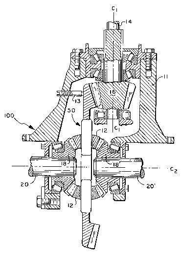
FIGURE 4 is a partially sectioned top view of an
embodiment of a differential gear assembly 100 of the
05 invention.
D~SCRIPTIO~ OF SOM~ PREFERRED FIMBODIMENTS
The prior art differential gear assembly 30 shown in
FIGURE l is of the type hereinbefore described requiring
numerous components and a much larger housing to enclose
them.
Assembly 30 is operative to transfer rotary torque
from a pinion gear 32 driven by a rotary output shaft 34
of a change gear transmission to a ring gear 36 having
teeth meshingly engaged with teeth on ring gear 36. Ring
gear 36 is secured to a frame 38 that is journaled for
rotation relative housing 42 by means of bearings 40. As
such, ring gear 36 and frame 38 rotate coaxially about
axle shaft 48 that has an end gear 43 secured to its
inboard end by suitable means such as splines. It can
thus readily be seen from FIGURE l that prior art
differential gear assemblies required precise and costly
alignment between the ring gear and the differential
housing.
Axle shaft 48 is spaced-apart from and substantially
axially aligned with axle shaft 48' which has an end gear
43' secured to its inboard end in facing relationship to
end gear 43. Axle shafts 48 and 48' have a cornmon central
rotational axis C2 that is substantially prependicular
to central rotational axis Cl of pinion gear 32.
End gears 43 and 43' are meshingly engayed with at
least two equi-circurnferentially spaced differential
pinion gears 4~ that are rotably mounted on frame 38 by

~g~5~j~'
--4--
means of pins 46. Rotation of frame 38 by ring gears 36
causes differential pinion gears 44 to rotate about axis
C2 and in turn cause end gears 43 and 43~ to rotate a~le
shafts 48and 48' about axis C2 respectively.
05 As can be seen in FIGURE l, axle shaft 48~ is
journaled for rotation relative housing 42 by means of
bearings 40' and both axle shafts 48 and 48' can be
removed from housing 42 with relative ease due to the
splined securernent with their respective end gears but
that precise alignment between ring gsar 36 and frame 38
and between differential pinion gears ~4 and end gears 43
and 43' is essential.
The ring gear and differential gear assembly of the
invention hereinafter described with respect to FIGURE 2,3
and 4 enable the elimination of frame 38 and the bolts
required to secure it to ring gear 36 as well as pins 46
in addition to enabling a substantial reduction in the
size of housing 42 due to the absence of frame 38 and in
addition to enabling the ring gear to float relative the
housing and the end gears secured to the axle shafts.
FIGU~E 2 shows ring gear 50 of the invention that is
adapted to float in the motor vehicle differential gear
assembly shown in FIGURE 4.
Ring gear 50 has a generally annular configuration
having a substantially circular outer periphery 4 and a
substantially circular inner periphery 6. As shown in
FIGURES 2 and 3, ring gear 50 has a plurality of
substantially evenly circumferentially spaced teeth 8
extending away from the side thereof between outer
periphery 4 and inner periphery 6. Teeth 8 are preferably
spiral bevel or hypoid type teeth having a curved tooth
path profile as shown in FIGURE 2 to enhance smooth
engagement with the teeth of pinion gear 16 shown in
FIGURE 2 which is also preferably provided with curved
teeth for promoting smooth continuous mesh with -teeth 8 of
ring gear 50. The use of spiral bevel or hypoid teeth in
vehicle differential gear assemblies to enhance smooth

'' J
--5--
transfer of torque is well known to those skilled in the
art and is not therefore reviewed here in detail.
In contrast to prior art type ring gears hereinbefore
described, ring gear 50 is provided with at least two and
05 preferably four substantially equi-circumferentially
spaced posts 10 (only two referenced) that extend radially
inwardly from inner periphery 6 and may be integral
therewith or secured thereto by welding or other suitable
securement means or may themselves be mounted so that they
are rotatable and differential pinion gears 12 are either
fi~edly secured thereto or rotatably mounted thereupon.
A differential pinion gear 12 is rotatably mounted on
each post 10 (only one shown in FIGURE 2).
Differential pinion gears 12 have diametrically
opposed teeth operative to simultaneously meshingly engage
with the teeth of side gears 18 and 18' hereinafter
described with respect to differential gear assembly 100
of FIGURE 4.
In FIGURE 4, a rotary driver member such as output
shaft 14 of a vehicle change gear transmission is received
through an opening in a housing 11 and suitably journaled
for rotation.
Shaft 14 has a pinion gear 16 secured to its end
having a central rotational axis referenced by "Cl".
Central rotational axis "C2" of ring gear 50 is
substantially perpendicular to axis Cl and the teeth of
both ring gear 50 and pinion gear 16 are adapted to
meshingly engage so that ring gear 50 rotates in response
to rotation of pinion gear 16.
Housing 11 preferably includes an adjustable screw 13
that is adapted to prevent deflection of the teeth of ring
gear 50 away from the teeth of pinion gear 16 to insure
meshed engagement therebetween.

,s
--6--
Ring gear 50 is disposed in the space between the ends
of substantially axially aligned wheel axle shafts 20 and
20' that also have axis "C2" as their common central
rota-tional axis. Side gears 18 and 18' are secured to the
05 spaced-apart facing ends of axle shafts 20 and 20'
respectively by suitable securement means such as splines
(not shown) and are journaled for rotation therewith. The
teeth of side gears 18 and 18' are adapted to meshingly
engage with the teeth of differential pinion gears 12 with
the combination adapted to provide support for ring gear
50 in the space between the ends of axle shafts 20 and 20'
as well as to enable ring gear 50 to rotate axle shafts 20
and 20' as it is rotated by pinion gear 16 in addition to
enabling ring gear 50 to "float" within the space between
the ends of axle shafts 20 ana 20' since it is not fixedly
journaled for rotation on housing 11 and thus reducing the
precise alignment characteristically required between such
components in the past.

Representative Drawing
A single figure which represents the drawing illustrating the invention.
Administrative Status

2024-08-01:As part of the Next Generation Patents (NGP) transition, the Canadian Patents Database (CPD) now contains a more detailed Event History, which replicates the Event Log of our new back-office solution.

Please note that "Inactive:" events refers to events no longer in use in our new back-office solution.

For a clearer understanding of the status of the application/patent presented on this page, the site Disclaimer , as well as the definitions for Patent , Event History , Maintenance Fee  and Payment History  should be consulted.

Event History

Description Date
Inactive: IPC deactivated 2011-07-26
Inactive: IPC from MCD 2006-03-11
Time Limit for Reversal Expired 1996-05-15
Application Not Reinstated by Deadline 1996-05-15
Deemed Abandoned - Failure to Respond to Maintenance Fee Notice 1995-11-15
Inactive: Adhoc Request Documented 1995-11-15
All Requirements for Examination Determined Compliant 1993-11-19
Request for Examination Requirements Determined Compliant 1993-11-19
Application Published (Open to Public Inspection) 1992-06-06

Abandonment History

Abandonment Date Reason Reinstatement Date
1995-11-15
Owners on Record

Note: Records showing the ownership history in alphabetical order.

Current Owners on Record
EATON CORPORATION
Past Owners on Record
JAMES R. LONG
Past Owners that do not appear in the "Owners on Record" listing will appear in other documentation within the application.
Documents

To view selected files, please enter reCAPTCHA code :


To view images, click a link in the Document Description column. To download the documents, select one or more checkboxes in the first column and then click the "Download Selected in PDF format (Zip Archive)" or the "Download Selected as Single PDF" button.

List of published and non-published patent-specific documents on the CPD .

If you have any difficulty accessing content, you can call the Client Service Centre at 1-866-997-1936 or send them an e-mail at CIPO Client Service Centre.


Document
Description 
Date
(yyyy-mm-dd) 
Number of pages   Size of Image (KB) 
Abstract 1992-06-06 1 14
Claims 1992-06-06 3 95
Drawings 1992-06-06 2 88
Cover Page 1992-06-06 1 12
Descriptions 1992-06-06 6 205
Representative drawing 1999-06-28 1 36
Fees 1994-09-21 1 78
Fees 1993-08-23 1 61