Language selection

Search

Patent 2055914 Summary

Third-party information liability

Some of the information on this Web page has been provided by external sources. The Government of Canada is not responsible for the accuracy, reliability or currency of the information supplied by external sources. Users wishing to rely upon this information should consult directly with the source of the information. Content provided by external sources is not subject to official languages, privacy and accessibility requirements.

Claims and Abstract availability

Any discrepancies in the text and image of the Claims and Abstract are due to differing posting times. Text of the Claims and Abstract are posted:

  • At the time the application is open to public inspection;
  • At the time of issue of the patent (grant).
(12) Patent Application: (11) CA 2055914
(54) English Title: DEVICE FOR HOLDING A VARIABLE NUMBER OF REAR-ILLUMINATED ADVERTISEMENT CARRIES CONSISTING OF A POSTER-LIKE BLANK
(54) French Title: DISPOSITIF SERVANT A TENIR UN NOMBRE VARIABLE DE SUPPORTS D'AFFICHAGE ECLAIRES PAR TRANSPARENCE ET FORMES D'ESPACES VIDES
Status: Deemed Abandoned and Beyond the Period of Reinstatement - Pending Response to Notice of Disregarded Communication
Bibliographic Data
(51) International Patent Classification (IPC):
  • G09F 11/32 (2006.01)
  • G09F 11/12 (2006.01)
  • G09F 13/04 (2006.01)
(72) Inventors :
  • FASSAUER, ANGELIKA (Germany)
  • HALUSZKA, PETER (Germany)
(73) Owners :
  • ANGELIKA FASSAUER
  • PETER HALUSZKA
(71) Applicants :
(74) Agent: SMART & BIGGAR LP
(74) Associate agent:
(45) Issued:
(22) Filed Date: 1991-11-20
(41) Open to Public Inspection: 1993-03-12
Availability of licence: N/A
Dedicated to the Public: N/A
(25) Language of filing: English

Patent Cooperation Treaty (PCT): No

(30) Application Priority Data:
Application No. Country/Territory Date
G 9111283.4 (Germany) 1991-09-11

Abstracts

English Abstract


Abstract
The invention concerns to a device for holding a variable num-
ber of rear-illuminated advertisement carriers consisting of a
posterlike blank, each advertisement carrier is mounted in a
pocket, open on one side, consisting of a transparent flexible
sheet and can be positioned by a drive device from a chamber
at the back panel to the region of the visible area and then
back to the chamber whereby each pocket follows a further pok-
ket which is soluble connected to the first pocket, and in the
region of the visible glass is arranged an illuminating
device. The drive mechanism consists of motor driven gears
which by means of toothed belts are in contact with the pok-
kets of the advertisement carriers.


Claims

Note: Claims are shown in the official language in which they were submitted.

-7-
Claims
1. Device for holding a variable number of rear-illumina-
ted advertisement carriers consisting of a posterlike
blank, each advertisement carrier is mounted in a pok-
ket, open on one side, consisting of a transparent fle-
xible sheet and can be positioned by a drive device
from a chamber at the back panel to the region of the
visible area and then back to the chamber whereby each
pocket follows a further pocket which is soluble con-
nected to the first pocket, and in the region of the
visible glass is arranged an illuminating-device, and
whereby the drive device consists at least of one pairs
of rollers with rollers being in distance for onean-
other, whereby over each roller of the at least one
pair of rollers an endless belt is fed which is able to
be an active engagement with the pockets to be fed to
the visible area, characterized in that each roller is
formed as a gear about which is fed as an endless belt
a single-pieced toothed belt or a toothed belt consist-
ting of toothed belt-strips, being in engagement with
the backside of a pocket of an advertisement carrier,
whereby at the front side of each pocket in advance
direction at one end section at the side border at
least one interlacing hook is arranged, which is in
soluble active engagement with the other end section of
a pocket which is ahead or behind in advance direction,
and whereby at the side walls of the housing guide
rails are formed, which are near the visible glass and
through which the pockets are led to the visible glass.
2. Device according to claim 1, with two pairs of rollers,
which in each case are arranged in sections of the hou-
sing being opposite to each other, characterized in
that respectively one gear of one pair of rollers is

-8-
connected to a gear of the other pair of rollers by
means of an endless band being a single-pieced toothed
belt.
3. Device according to claim 2, characterized in that the
thoothed belts are in soluble engagement within the
backside of a pocket in the area of the visible glass.
4. Device according to claim 2, characterized in that the
toothed belts are douple sided toothed and the tooth
profiles opposite to the gears engages toothed belt-
strips, being arranged on the backside of the pockets,
in the area of the visible glass.
5. Device according to claim 4, characterized in that, the
toothed belt-strips at the backside of the pockets are
formed as an arrangement of toothed belt pieces.
6. Device according to claim 5, characterized in that, the
toothed belt-strips extends single pieced over the
length of the pockets in advance direction.
7. Device according to claim 2, characterized in that on
the smoothed backsides of toothed belts are arranged
clamping bands which in the area of the visible glass
engages clamping bands on the backside of pockets.
8. Device according to claim 1, characterized in that the
end section of guide rails are led to the inlet area
and outlet area of the chamber between back panel and
rear dividing wall.
9. Device according to claim 1, at which one pair of rol-
lers is motorized driven and the common shaft for the
rollers is formed as drive shaft, characterized in
that, a further gear is mounted at the drive shaft

-9-
being connected to the drive gear of a driving motor by
a toothed belt.
10. Device according to claim 9, characterized in that the
driving motor is an electrical back-geared motor.
11. Device according to claim 9, characterized in that the
driving motor is actuated timed clock-controlled.
12. Device according to claim 1, characterized in that,
each pocket consists of two blanks of transparent foil,
from which the breadth of the rear blank is equal to
the distance between the guide rails and the front
blank is arranged on the rear blank in such a manner
that in advance direction on the rear blank are formed
lateral edge strips.
13. Device according to claim 12, characterized in that, on
the backside of edge strips in each case is mounted a
toothed belt or a clamping band respectively and at the
front side of edge strips in the area of one end sec-
tion of the pocket is arranged at least one interlacing
hook.
14. Device according to claim 13, characterized in that at
the end section of the pocket opposite to the end sec-
tion with at least one interlacing hook the blanks are
soluble connected by a profile cramping strip, through
which a profile rod is led which extends over the
breadth of this end section having rod tips which in
each case are soluble be connected with an interlacing
hook.
15. Device according to claim 14, characterized in that in
the area of the rod tips are formed jogs in the edge
strips.

-10-
16. Device according to claim 14, characterized in that,
each interlacing hook consists of a base plate with an
integrated holding piece with an one side opened recess
into which a rod tip may be fed.
17. Device according to claim 16, characterized in that the
outer surface of each holding piece is formed as slide
off surface being angular to the plane of the base
plate.
18. Device according to claim 12, characterized in that on
the backside of edge strips of the rear blanks toothed
belt-strips are arranged.
19. Device according to claim 12, characterized in that the
rear blank consists of a transparent foil of opal-white
colour.

Description

Note: Descriptions are shown in the official language in which they were submitted.


2~9~
The invention concerns to a device ~or holding a variable num-
ber of rear-illuminated advertisement carriers consisting of a
posterlike blank, each adverti6ement carrier is mounted in a
pocket, open on one side, consisting of a transparent flexible
sheet and can be positioned by a drive device from a chamber
at the back panel to the region of the visible arPa and then
back to the chamber whereby each pocket follows a further pok-
ket which is soluble connected to the first pocket, and in the
region of the visible glass is arranged an illuminating-de-
vice, and whereby the drive device consists at least of one
pair of rollers which rollers being in distance from oneano
ther, whereby over each roller of the at least one pair of
rollers an endle~s belt is fed which is able to be in active
engagement with the pockets to be fed to the visible area.
Such a device is known by EP 0419732 A1. The object of the
invention consists in improving the device of the initially
described type so that the transport of the advertisement car-
riers from the chamber to take up the advertisement carriers
to the visible area at the field of the visible glass and back
to the chamber is simplified and safer.
The object is achieved according to the invention by means of
the features that each roller is formed as a gear about which
is fed as an endless belt a singla pieced toothed belt or a
toothed belt consigting of toothed belt-strips, being in enga-
gement wi~h the backside of a pocket of an advertisement car-
rier, whereby at the front side of each pocket in advance
direction at one end section at the side border at least one
interlacing hook is arranged, which is in soluble active eng~-
gement with the other end section of a pocket which is ahead
or behind in advance direction, and whereby at the side walls
of the housing guide rails are formed which are near the visi-
ble glass and through which the pockets are fed to the visible
P916068C.DOC

-2-
glass.
Advantageous configurations of the invention are discribed in
the dependent claims.
Decisive advantage of the drive device according to the inven-
tion is the fact that the toothed belts are furnished which
teeth of narrow distance between oneanother. Therefore any
tooth of the toothed belt is able to take over the transport
of an advertisement carrier~ There is no defined point at the
toothe~ belt for taking over the transport. Therefore the too-
thed belts may be of undefined length. Decisive is only the
right position of the drive shaft for the driven gears. Accor-
ding to a further embodiment of the invention it is possible
to decrease the number of wearing parts of the device if the
toothed belts for actuation are arranged at the backside o~
each pocket of an advertisement carrier. In this case the too-
thed belts are made of toothed belt-strips. This device must
be started manually however. The first pocket must be put on
the gears. After rotation of the drive shaft by the driving
motor the pockets within the device shape an endless loop
automatically.
The invention is explained in greater detail below by embodi-
ments of the device according to the invention represented in
the drawings. There are shown in:
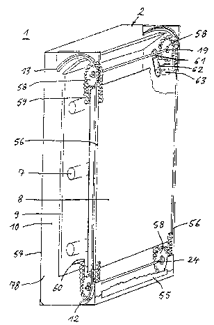
Fig.l a device in a perspective view,
Fig.2 the device according to Fig.1 in a sectional side view,
Fig.3 the device according to ~ig.l with thP schematically
presentation of the function,
Fig.4 an interlacing hook for soluble connection of two
advertisement carrier in a perspective view,

2~91~
--3~
28396-2
Fig. 5 a pocket of an advertisement carrier in a front
view,
Fig. 6 a side view of the pocket shown in Fig. 5,
Fig. 7 a further embodiment of a device in a sectional
side view.
Device 1 consists of a housing 2 the front wall of
which is formed as visible area for an advertisement carrier 4
by a visible glass 55. Within the housing 2 a front transparent
guide waIl 8 and a rear dividing wall 9 is arranged. Between the
dividing wall 9 and the guide wall 8 an illumination device is
placed in a chamber. The space between dividing wall 9 and back
panel 57 is formed as chamber 10 for receiving advertisement
carrier 4 vertically one behind the other. ~t each side wall 78
is arranged one guide rail 56 close to the visible glass 55 the
end sections of which are led up to the intake opening 12 and
outlet opening 13 of chamber 10. The pockets 11 are guided
wlthin the guide rails 56 during transport before the visible
~ g1ass 55.
;~ ~ At the upper and lower end section of housing 2 in
;20 each case a pair of gears 58 is arranged each of which being
located-near the side walls 78. The upper gears 58 are connected
to a drive shaft 19. A further gear 61 is connected to the
drive shaft 19 being connected to the drive gear of a driving
motor 63 by a toothed belt 62. This driving motor 63 may be for
instance an electrical back-geared motor. It is of advantage
to actuate the driving motor 63 timed clock - controlled so that
: : :
each advertisement carrier 4 to be guided before the visible
glass 55 will rest there for a predetermined dwell time. The
.

20a~
-3a-
28396-2
lower gears 58 are connected by a drive shaft 24. Each lower
gear 58 operates interlocked by a one-pieced toothed belt 59
with an upper gear 58.
The toothed belt 59 may be toothed double sided. In
this case the tooth profiles of the toothed belt 59 opposite to
the

-4- 2 ~
gears 58 are in operative connection to the toothed belt-
strips 79 in the area of visible glass 55, whereby the toothed
belt-strips 79 are arranged on the backside of pockets 11 of
advertisement carriers 4. These toothed belt-strips 79 may be
one-pieced or formed as arrangement of pieces of a toothed
belt. They extend preferably over the length of pockets 11 in
advance direction. It is even possible to form the backsides
of toothed belts 59 smoothed. In this case at the back~ide of
toothed belts 59 clamping bands are brought up which engages
with clamping bands on the backside of pockets 11 of adverti-
sement carriers 4 in the region of visible glass 55. Conditio-
nal on the restricted guidance o~ pockets 11 in the guide
rails 56 the toothed belt-strips 79 or clamping bands respec-
tively of pockets 11 are brought commpulsorily into engagement
of teeth 60 of toothed belts 59 or the clamping bands on too-
thed belts 59 respectively. Each pocket 11 shows interlacing
hooks 67 through which the pocket 11 following the first pok-
ket 11 is drawn after (Fig.3). The interlacing hooks 67 will
be described detailed further below.
The pockets 11 of advertisement carriers 4 consists of two
blanks 65, 66 which are of a transparent flexible sheeting.
The breadth of the rear blank 65 is equal to the distance of
guide rails 56 from each other. The forward blanX 6~ is arran-
ged at the rear blank 65 in such a way that in advance direc-
tion on each side of the rear blank 65 an edge strip 68l 69 is
formed ~Fig.5). On the backside of edge strips 68, 69 in each
case a toothed belt-strip 79 or, repsectively, a clamping band
is arranged. Vn the front side of edge strips 68, 69 in the
area of one end ssction 14 of pocket 11 in each case an inter-
lacing hook Z7 is arranged. The interlacing hooks 67 may be
connected to the edge strips 68, 69 by rivets or adhesive sub-
stance. Each interlacing hook 67 has 2 base plate 75 for con-
nection with an edge strip 68, 69. On the base plate 75 is
formed a holding piece 76 with an one side opened recess 77.
The external surfaces of the holding piecss 76 are arranged to

~5~ 2 ~
the plane of base plates 75 angular formed as wedge-shaped
slide-off surfaces 72 (Fig.4). By this it is easier to release
the connection between the advertisement carrier ~ within the
chamber 10 as at the angular formed wedge-shaped slide-o~f
surfaces 72 the edges of the below described jogs 74 of blanks
6~ are able to slide down. At end section 15 opposite to end
section 14 the blanks 65, 55 are soluble connected by a pro-
file cramping strip 70. A profila rod 71 is led through the
profile cramping strip 70 over the breadth of end section 15.
The rod tips 73 o~ profile rod 71 are to be grabbed by a one
side opening recess of the one interlacing hook 67. At the
region of each rod tip 73 a jog 74 is made in edge strips 68,
69 which makes it easier to detach rod tips 73 of one pocket
11 from interlacing hooks 67 of forward pocket 11 in chamber
10 .
The blanks 65~ 66 may be connected at the ends by an adhesive
band able to be re-picked up. The adhesive band may be of thin
material being transparent. By this a pocket 11 i formed into
which for instance an advertisement poster or the like may be
put in.
For adchieving a carrier connection between toothed belt 59
and toothed belt-strips 79 of pockets 11 various different
profiles may be applied which guarantee such a carrier csnnec-
tion. Decisive is that by means of restricted guidance through
guide rails 56 the toothed belts 59 are brought in connection
to the pocket 11 and after finished transport an independent
separation takes place.
Fig.7 shows a device la for which only the motorized driven
upper gears 58 and toothed belt strips 79 on the backside of
edge strips 68, 69 are necessary. The fastening of toothed
belt-strips 79 on edge strips 68, 69 may be done by bonding
agent or rivets. If the blank 65 is made of foil being
transparent and of opal-white colour no front transparent

2 ~ 3 ~
guide wall 8 is necessary. For the function of this device la
it is decisiva that the pockets 11 and the edges are guided by
the guide rails 56. At initial operation of the device la it
is necessary in each case to bring the first pocket 11 in ope-
rating connection with ~ears 58. By rotation of gears 58 then
an endless band is formed by pockets 11 in the chamber 10.

Representative Drawing
A single figure which represents the drawing illustrating the invention.
Administrative Status

2024-08-01:As part of the Next Generation Patents (NGP) transition, the Canadian Patents Database (CPD) now contains a more detailed Event History, which replicates the Event Log of our new back-office solution.

Please note that "Inactive:" events refers to events no longer in use in our new back-office solution.

For a clearer understanding of the status of the application/patent presented on this page, the site Disclaimer , as well as the definitions for Patent , Event History , Maintenance Fee  and Payment History  should be consulted.

Event History

Description Date
Inactive: IPC from MCD 2006-03-11
Time Limit for Reversal Expired 1997-11-20
Application Not Reinstated by Deadline 1997-11-20
Deemed Abandoned - Failure to Respond to Maintenance Fee Notice 1996-11-20
Application Published (Open to Public Inspection) 1993-03-12

Abandonment History

Abandonment Date Reason Reinstatement Date
1996-11-20
Owners on Record

Note: Records showing the ownership history in alphabetical order.

Current Owners on Record
ANGELIKA FASSAUER
PETER HALUSZKA
Past Owners on Record
None
Past Owners that do not appear in the "Owners on Record" listing will appear in other documentation within the application.
Documents

To view selected files, please enter reCAPTCHA code :


To view images, click a link in the Document Description column. To download the documents, select one or more checkboxes in the first column and then click the "Download Selected in PDF format (Zip Archive)" or the "Download Selected as Single PDF" button.

List of published and non-published patent-specific documents on the CPD .

If you have any difficulty accessing content, you can call the Client Service Centre at 1-866-997-1936 or send them an e-mail at CIPO Client Service Centre.


Document
Description 
Date
(yyyy-mm-dd) 
Number of pages   Size of Image (KB) 
Abstract 1993-03-11 1 20
Claims 1993-03-11 4 141
Drawings 1993-03-11 4 97
Descriptions 1993-03-11 7 248
Representative drawing 1999-06-01 1 21
Fees 1995-11-14 1 40
Fees 1994-11-20 1 41
Fees 1993-09-13 1 32