Language selection

Search

Patent 2055944 Summary

Third-party information liability

Some of the information on this Web page has been provided by external sources. The Government of Canada is not responsible for the accuracy, reliability or currency of the information supplied by external sources. Users wishing to rely upon this information should consult directly with the source of the information. Content provided by external sources is not subject to official languages, privacy and accessibility requirements.

Claims and Abstract availability

Any discrepancies in the text and image of the Claims and Abstract are due to differing posting times. Text of the Claims and Abstract are posted:

  • At the time the application is open to public inspection;
  • At the time of issue of the patent (grant).
(12) Patent Application: (11) CA 2055944
(54) English Title: GUIDEWAY FOR RAPID TRANSIT SYSTEM
(54) French Title: GUIDE POUR SYSTEME DE TRANSPORT URBAIN RAPIDE
Status: Deemed Abandoned and Beyond the Period of Reinstatement - Pending Response to Notice of Disregarded Communication
Bibliographic Data
(51) International Patent Classification (IPC):
  • E01B 25/10 (2006.01)
(72) Inventors :
  • TADROS, GAMIL S. (Canada)
  • LOCKWOOD, PHILLIP JOHN (Canada)
(73) Owners :
  • GAMIL S. TADROS
  • PHILLIP JOHN LOCKWOOD
(71) Applicants :
  • GAMIL S. TADROS (Canada)
  • PHILLIP JOHN LOCKWOOD (Canada)
(74) Agent: KIRBY EADES GALE BAKER
(74) Associate agent:
(45) Issued:
(22) Filed Date: 1991-11-21
(41) Open to Public Inspection: 1993-05-22
Availability of licence: N/A
Dedicated to the Public: N/A
(25) Language of filing: English

Patent Cooperation Treaty (PCT): No

(30) Application Priority Data: None

Abstracts

English Abstract


ABSTRACT
A double track aerial guideway for a rapid transit system
has a central vertical spine and a pair of roadways projecting
horizontally from respective sides of the spine. The spine is
such as to have a horizontal upper surface that is located at
approximately the same elevation as the passenger floor of a
vehicle on one of the roadways, this upper surface serving the
function of an emergency walkway.


Claims

Note: Claims are shown in the official language in which they were submitted.

CLAIMS
1. A double track guideway for a rapid transit system,
comprising a central vertical spine and a pair of horizontal
roadways projecting from respective sides of the spine
vertically intermediate upper and lower portions of said
spine, a horizontal surface at an upper portion of the spine
providing a walkway at approximately the same elevation as a
passenger floor of a vehicle on one of the roadways.
2. A guideway according to claim 1, including a
vertical barrier at the edge of each roadway remote from the
spine to act as a crash and sound barrier.
3. A guideway according to claim 1, including bracing
members extending upwardly and outwardly from the lower
portion of the spine to outer portions of respective roadways.
4. A guideway according to claim 1, wherein the spine
is a single monolithic vertical member.
5. A guideway according to claim 1, wherein the spine
is formed of a pair of spaced-apart members that converge
upwardly from respective ends of a horizontal lower portion of
the spine to said upper portion of the spine on which the
walkway is provided.

Description

Note: Descriptions are shown in the official language in which they were submitted.


2~35~
GUIDEWAY FOR RAPID TRANSIT SYSTEM
FIELD OF THE INVENTION
The invention relates to a doub:Le track guideway for a
rapid transit system and more specif:ically to a guideway that
is suitable for use as an aerial guideway.
BACKGROUND OF THE INVENTION
In the past, guideway superstructures have been designed
to support both transit vehicles and an associated emergency
walkway. Typically, the walkway has been suspended from the
side of the guideway structure or has been vertically
supported by and placed on the superstructure.
SUMMARY OF THE INVENTION
The object of the present invention is to provide an
improved profile of guideway structure, and more particularly
a profile that facilitates the location of the walkway
relative to the roadways, and minimizes the l'bulk" of the
structure for a given length of span between two piers.
To this end, the invention provides a double track
guideway for a rapid transit system, comprising a central
vertical spine and a pair of horizontal roadways projecting
from respective sides of the spine vertically intermediate
upper and lower portions of said spine, wherein a horizontal
surface at an upper portion of the spine provides a walkway at
approximately the same elevation as a passenger floor of a
vehicle on one of the roadways.
In referring above to the minimization of bulk, it should
be explained that in this context the term "bulk" relates to
the side appearance of the structure. To span a distance
between two piers, a structural load carrying beam is
required, typically having a depth of approximately one
twentieth of the span distance. The present construction o~
guideway effectively "hides" a portion of the spine (which

2 ~
forms the beam), by vir~ue of the location of the roadways at
the sides of the spine a distance (typically approximately
feet) below the upper surface of the spine that forms the
walkway. The result is a mor~ pleasing appearance because the
structure seems to be less massive when viewed from the side,
compared with prior constructions in which the roadways are
located above the top of the spine.
Preferably, the guideway also has a vertical barrier at
the outer edge of each roadway to act as a crash and sound
barrier.
The outer portions o~ the roadways are preferably
supported by bracing members that extend upwardly and
outwardly from the lower portion of the spine.
The spine may be a single monolithic ~ertical member, or
may be divided into a pair of spaced-apart members that
converge upwardly from respective ends of a horizontal lower
portion of the spine to the upper portion of the spine that
forms the walkway.
BRIEF DESCRIPTION OF THE DRAWINGS
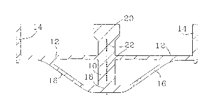
Figure l is a profile, i.e. cross-section, of an aerial,
double track guideway for a rapid transit system, according to
a first embodiment of the present invention; and
Figure 2 is a similar view of a second embodiment.
D~TAILED DES~RIPTION OF THE PR~FERRED EMBODIMENT
The double track guideway shown in Figure l consists of a
central, vertical load carrying spine l0 from each side of
which there extends a road surface 12 that terminates in a
vertical barrier 14. The outer ends of the road surfaces 12
are further supported by bracing members 16 that extend
upwardly and outwardly from the lower portion 18 of the spine
l0. The upper surface 20 of the spine l0 is flat and slightly
widened to pro~ide an emergency walkway.
Slots shown at 22 are optional and may be used for
control of concrete cracking (due to the heat of cement
hydration) of thick concrete sections.

2 ~
Figure 2 shows an alternative in which the spine is
divided into two upwardly converging portions 10A and 10B.
Otherwise this construction is essentially the same as that of
Figure 1, with the upper surface 20 of the spine still
providing the emergency walkway. An optional support system
24 can be provided using cable stays in order to achieve even
longer span lengths.
These embodiments of the invention will be formed of
conventional construction materials, such as reinforced
concrete, being configured as either continuous plate or
space-frame construction, and will be designed to extend
longitudinally between conventional supporting piers (not
shown) in order to constitute an aerial guideway.
Each road surface 12 will be of appropriate width to
accommodate a single vehicle, such as a bus or a rail vehicle.
The continuous vertical barriers 14 will function both as a
vehicle crash barrier and a sound barrier. The top surface 20
of the spine is at the same elevation as the passenger floor
of the vehicle, which permits such surface 20 to function as a
conveniently located emergency walkway, and the roadways are
located vertically intermediate the upper and lower portions
of the spine whereby to reduce the bulkiness of the appearance
of the structure, an explained above.

Representative Drawing
A single figure which represents the drawing illustrating the invention.
Administrative Status

2024-08-01:As part of the Next Generation Patents (NGP) transition, the Canadian Patents Database (CPD) now contains a more detailed Event History, which replicates the Event Log of our new back-office solution.

Please note that "Inactive:" events refers to events no longer in use in our new back-office solution.

For a clearer understanding of the status of the application/patent presented on this page, the site Disclaimer , as well as the definitions for Patent , Event History , Maintenance Fee  and Payment History  should be consulted.

Event History

Description Date
Inactive: Inventor deleted 2002-05-13
Time Limit for Reversal Expired 1994-05-21
Application Not Reinstated by Deadline 1994-05-21
Deemed Abandoned - Failure to Respond to Maintenance Fee Notice 1993-11-22
Inactive: Adhoc Request Documented 1993-11-22
Application Published (Open to Public Inspection) 1993-05-22

Abandonment History

Abandonment Date Reason Reinstatement Date
1993-11-22
Owners on Record

Note: Records showing the ownership history in alphabetical order.

Current Owners on Record
GAMIL S. TADROS
PHILLIP JOHN LOCKWOOD
Past Owners on Record
None
Past Owners that do not appear in the "Owners on Record" listing will appear in other documentation within the application.
Documents

To view selected files, please enter reCAPTCHA code :


To view images, click a link in the Document Description column. To download the documents, select one or more checkboxes in the first column and then click the "Download Selected in PDF format (Zip Archive)" or the "Download Selected as Single PDF" button.

List of published and non-published patent-specific documents on the CPD .

If you have any difficulty accessing content, you can call the Client Service Centre at 1-866-997-1936 or send them an e-mail at CIPO Client Service Centre.


Document
Description 
Date
(yyyy-mm-dd) 
Number of pages   Size of Image (KB) 
Claims 1993-05-21 1 26
Abstract 1993-05-21 1 12
Drawings 1993-05-21 1 17
Descriptions 1993-05-21 3 118
Representative drawing 1998-10-27 1 6