Language selection

Search

Patent 2056029 Summary

Third-party information liability

Some of the information on this Web page has been provided by external sources. The Government of Canada is not responsible for the accuracy, reliability or currency of the information supplied by external sources. Users wishing to rely upon this information should consult directly with the source of the information. Content provided by external sources is not subject to official languages, privacy and accessibility requirements.

Claims and Abstract availability

Any discrepancies in the text and image of the Claims and Abstract are due to differing posting times. Text of the Claims and Abstract are posted:

  • At the time the application is open to public inspection;
  • At the time of issue of the patent (grant).
(12) Patent Application: (11) CA 2056029
(54) English Title: MULTIPHASE FLOW RATE MONITORING MEANS AND METHOD
(54) French Title: DISPOSITIF ET METHODE DE CONTROLE MULTIPHASE DE DEBITS
Status: Deemed Abandoned and Beyond the Period of Reinstatement - Pending Response to Notice of Disregarded Communication
Bibliographic Data
(51) International Patent Classification (IPC):
  • G01N 01/10 (2006.01)
  • G01F 01/74 (2006.01)
  • G01F 01/86 (2006.01)
  • G01F 15/08 (2006.01)
  • G01N 01/20 (2006.01)
  • G01N 09/00 (2006.01)
(72) Inventors :
  • DEAN, TIMOTHY LEE (United Kingdom)
  • DOWTY, EARL LEONARD (United States of America)
  • STARTUP, IAN (United Kingdom)
(73) Owners :
  • TEXACO DEVELOPMENT CORPORATION
  • TEXACO LIMITED
(71) Applicants :
  • TEXACO DEVELOPMENT CORPORATION (United States of America)
  • TEXACO LIMITED (United Kingdom)
(74) Agent: SMART & BIGGAR LP
(74) Associate agent:
(45) Issued:
(22) Filed Date: 1991-11-22
(41) Open to Public Inspection: 1992-07-04
Availability of licence: N/A
Dedicated to the Public: N/A
(25) Language of filing: English

Patent Cooperation Treaty (PCT): No

(30) Application Priority Data:
Application No. Country/Territory Date
07/637,024 (United States of America) 1991-01-03

Abstracts

English Abstract


MULTIPHASE FLOW RATE MONITORING MEANS AND METHOD
(D#72,500-UKL-018 -F)
ABSTRACT OF THE DISCLOSURE
The flow rate monitor includes a test line containing a
chamber wherein the test line is declinated at a predetermined
angle so stratification of liquid and gas will occur in the
chamber. A sample stream is removed from the liquid in the chamber
and provided to a separator which separates the gas from the sample
stream to provide a gas output and a liquid output. The gas output
and the liquid output is returned to the test line. The water cut
of the liquid output is determined while the pressure of the
composite petroleum stream is sensed along with the temperature.
The volumetric flow rate of the composite petroleum stream is
monitored and the flow rate signal is provided. The density of the
composite petroleum stream is also monitored. The flow rate of all
three components of the composite petroleum stream is determined in
accordance with the temperature signal, the pressure signal, the
water cut signal, the flow rate signal and the density signal.
rgg72500.app


Claims

Note: Claims are shown in the official language in which they were submitted.

The embodiments of the invention in which an exclusive
property or privilege is claimed are defined as follows:
1. A flow rate means for monitoring a composite
petroleum stream having a gas component, an oil component and a
water component comprising:
a test line containing a chamber, said test line
being declinated at a predetermined angle so that stratifications
of liquid and gas will occur in the chamber,
sampling means for providing a sample stream from
the liquid in the chamber,
means for separating gas from the sample stream to
provide a gas output and a liquid output,
means for returning the gas output and the liquid
output to the test line,
water cut means for determining the water cut of the
liquid output and providing a water cut signal corresponding
thereto,
pressure means for sensing the pressure of the
composite petroleum stream and providing a pressure signal
corresponding thereto,
temperature means for sensing the temperature of the
composite petroleum stream and providing a temperature signal
representative thereof,
flow rate means for monitoring the volumetric flow
rate of the composite petroleum stream and providing a flow rate
signal corresponding thereto,
density means for monitoring the density of the
composite petroleum stream and providing a density signal
representative thereof, and
deriving means for deriving the volumetric flow
rates of the components of the composite petroleum stream in
accordance with the temperature signal, the pressure signal, the
water cut signal, the flow rate signal and the density signal.
rgg72500.app
- 6 -

2. Means as described in Claim 1 in which the deriving
means includes:
means for storing PVT density values, and
gas fraction means for deriving the volumetric gas
fraction in accordance with the water cut signal, the PVT density
for the composite stream, the PVT density for the oil component,
and the density of the water/brine component.
3. Means as described in Claim 2 in which the gas
fraction means derives the volumetric gas fraction X gas in
accordance with the following equation:
(1) X gas = [D comp-[D oil(1-XH2O)+DH2O (HH2O]]/[D gas
-[D oil (1-XH2O) + DH2O (XH2O)]
where X gas is the volumetric gas fraction of the composite
petroleum stream at its actual pressure and temperature, XH2O is the
volumetric water/brine fraction (water cut) of the oil and water
components of the composite petroleum stream at their actual
temperature and pressure (measured by monitors 44), D comp is the
density of the composite petroleum stream at its actual pressure
and temperature (measured by densitometer 39), D gas is the density
of the gas component of the composite petroleum stream at its
actual temperature and pressure (determined from PVT data for the
gas and oil of the composite petroleum stream at its actual
pressure and temperature), D oil is the density of the oil
component of the composite petroleum stream at its actual pressure
and temperature (determined from PVT data for the gas and oil of
the composite petroleum stream, and DH20 is the density of water
component of the composite petroleum stream at its actual pressure
and temperature. Obviously, from the foregoing, the various PTV
density values are stored in computer means 50 memory and computer
means 50 uses the stored values as required.
4. Means as described in Claim 3 for deriving the
rgg72500.app
- 7 -

volumetric flow rate Q gas of the gas fraction, the volumetric flow
rate Q H2O of the water/brine fraction, and the volumetric flow rate
Q oil. of the oil fraction in accordance with the following
formulas:
Q gas = (X gas) (Q comp),
QH2O = (Q comp - Q gas), and
Q oil = (1 - XH2O) (Q comp - Q gas)
rgg72500.app - 8 -

5. A method for monitoring the component flow rates of a
composite petroleum stream having a gas component, an oil component
and a water component comprising the steps of:
declinating at a test line, containing a chamber,
at a predetermined angle so that stratifications of liquid and gas
will occur in the chamber,
providing a sample stream from the liquid in the
chamber,
separating gas from the sample stream to provide a
gas output and a liquid output,
returning the gas output and the liquid output to
the test line,
determining the water cut of the liquid output,
providing a water cut signal corresponding to the
determined water cut,
sensing the pressure of the composite petroleum
stream,
providing a pressure signal corresponding to the
sensed pressure,
sensing the temperature of the composite petroleum
stream,
providing a temperature signal representative of
the sensed temperature,
monitoring the volumetric flow rate of the
composite petroleum stream,
providing a flow rate signal corresponding to the
monitored flow rate,
monitoring the density of the composite petroleum
stream
providing a density signal representative of the
monitored density, and
deriving the volumetric flow rates of the
components of the composite petroleum stream in accordance with the
temperature signal, the pressure signal, the water cut signal, the
rgg72500.app - 9 -

flow rate signal and the density signal.
6. A method as described in Claim 5 in which the
deriving step includes:
storing PVT density values, and
deriving the volumetric gas fraction in accordance
with the water cut signal, the PVT density for the composite
stream, the PVT density for the oil component, and the density of
the water/brine component.
7. A method as described in Claim 6 in which the gas
fraction step derives the volumetric gas fraction X gas in
accordance with the following equation:
(1) X gas = [D comp-[D oil (1-XH2O)+DH2O) (HH2O]]/[D gas
-[D oil (1-XH2O) +DH2O (XH2O)]
where X gas is the volumetric gas fraction of the composite
petroleum stream at its actual pressure and temperature, XH2O is the
volumetric water cut of the sample stream at its actual
temperature and pressure D comp is the density of the composite
petroleum stream at its actual pressure and temperature, D gas is
the density of the gas component of the composite petroleum stream
at its actual temperature and pressure (determined from PVT data
for the gas and oil of the composite petroleum stream at its actual
pressure and temperature), D oil is the density of the oil
component of the composite petroleum stream at its actual pressure
and temperature (determined from PVT data for the gas and oil of
the composite petroleum stream), and DH2O is the density of water
component of the composite petroleum stream at its actual pressure
and temperature.
8. A method as described in Claim 7 in which the step
volumetric flow rates includes deriving the volumetric flow rate Q
gas of the gas fraction, the volumetric flow rate QH2O of water
rgg72500.app - 10 -

fraction, and the volumetric flow rate Q Oil of the oil fraction in
accordance with the following formulas:
Q gas = (X gas) (Q comp),
QH2O = (Q comp - Q gas), and
Q oil = (1 - XH2O) (Q comp - Q gas)
rgg72500.app - 11 -

Description

Note: Descriptions are shown in the official language in which they were submitted.


2 ~3 ~
MULTIPHASE FLOW RATE MONITORING ~NS AND METHOD
(D#72,500-UKL-018-F)
BACKGROUND ~F THE INVENTION
Field of the Invention
The present invention relates to petroleum stream
analyzers.
UMMARY OF THE_ENVENTION
The flow rate monitor, of the present invention,
monitors a composite petroleum stream and includes a test line
containing a chamber wherein the test line and chamber are
declinated at a predetermined angle so that stratification of the
composite petroleum stream into liquid and gas fractions will occur
in the chamber. A sample stream is removed from the liguid in the
chamber and provided to a separator which separates the entrained
gas from the sample stream to provide a gas output and a liquid
output. The gas output and the liquid output are returned to the
test line. The water cut of the liquid output is determined while
the pressure of the composite petroleum stream is sensed along with
the temperature. The volumetric flow rate of the composite
petroleum stream is monitored and a flow rate signal is provided.
The density of the composite petroleum stream is also monitored.
The volumetric flow rates of all three components of the composite
petroleum stream are determined in accordance with the temperature
signal, the pressure signal, the water cut signal, the flow rate
signal and the density signal.
The objects and advantaqes of the invention will appear
more fully hereinafter, from a consideration of the detailed
description which ~ollows, taken together with the accompanying
drawing, wherein one embodiment is illustrated by way of example.
It should be expressly understood, however, that the drawing is for
illustration purposes only and is not tG be construed as defining
the limits of the invention.
rgg72500.app
,
,
. ,
: , ,

2 ~
VESCRIPTION OF THE DRAWING
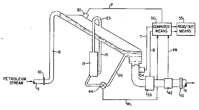
The drawing is in part a simplified block diagram and in
part schematic showing a flow rate monitor, constructed in
accorclance with the present invention, for a multiphase petroleum
strearn.
DESCRIPTION OF THE INVEN~ION
The present invention represents a new design for
metering gas, oil and water/brine production rates that will
perform at least equal to, or better than conventio~al designs. It
should be noted that the word "water" shall be used hereinafter in
lieu of "water/brine" and shall cover any water regardless of
salinity. Furthermore, the design of the present invention is more
reliable and can be made more compact and less expensive than
commercially available metering systems. The present invention is
suitable for measuring the individual flow rates of oil, gas and
water components of a multiphase petroleum stream, such as a
composite production stream from an oil well. The meter is
suitable for installation subsea, at the surface of the sea, on an
offshore platform, or onshore. The meter can be sized to
accommodate wide ranges of liquid and gas flow rates with water
cuts from zero to 100 percent.
Referring now to the Figure, there is shown a pipeline 5
connected to a test line 8, as indicated by flanges 10. Test line
8 rises vertically and then slopes down at a predetermined anqle
sufficient to stratify the composite petroleum stream. At the end
of the sloping portion of test line 8, the diameter is increased
substantially so as to form a chamber 12 before going to a vertical
descent. Test line 8 is turned thro~gh 90 from the vertical
portion to a horizontal direction before reconnection to pipeline
5. The composite petroleum stream, while passing through test line
8, will tend to stratify by the action of gravity such that liguid
flows along the bottom of the sloping pipe with gas flowing along
rgg72500.app
.
, . .:: :
~,
: ~ '
- ~

2 ~ '3~
the top. A sample stream of the liyuid component of the composite
petroleum gtream containing some entrained gas is removed by a
sampling line 15 and provided to a ~eparator 19. Separator 19
allows the entrained gas in the sample stream to separate from the
liquid and be returned to the gas portion of test line n via line
12.
The liquid portion of the sample stream in line 15 is
returned to the production stream in chamber 12 through a line 26.
During the flowing of the petroleum stream through pipeline 5 and
test line 8, certain parameters are measured. One parameter is
pressure, which is being sensed by a pressure sensor 30 providing
a signal P corresponding to the sensed pressure. A temperature
sensor 34 senses the temperature of the liquid flowing in test line
8 just prior to entering pipeline 5 again. Temperature sensor 34
provides a signal T corresponding to the sensed temperature. Also
in the discharge portion of test line 8, a densitometer 39 provides
a signal D corresponding to the density of the fluid exiting
pipeline 5.
A volumetric flowmeter 42 senses the flow rate of the
petroleum stream re-entering pipeline 5 and provides a
corresponding signal FR. A net oil or water cut meter 44 provides
a signal WC corresponding to the net oil or water cut of the sample
stream exiting separator 19.
Signals P, T, D, FR and WC, are provided to computer
means 50, which provides signals to readout means 55 corresponding
to the flow rates of the oil, water and gas.
rgg72500.app
-- 3 --
-

- ` 2 f`~
Computer means solves the following equations:
(1) X gas = [D comp-[D oil(l-XN20)+DH~ (H~ ]~/[ g
-[D oil (1 XH~) +DH~ ( ~) ]
where X gas is the volumetric gas fraction of the composite
petroleum stream at its actual pressure and temoperature, XH~ is
the volumetric water fraction ~water cut) of the oil and water
components of the composite petroleum stream at their actual
temperature and pressure (measured by monitors 44), D comp is the
density of the composite petroleum stream at its actual pressure
and temperature (measured by densitometer 39), D gas is the density
of the gas component of the composite petroleum stream at its
actual tempoerature and pressure (determined from PVT data for the
gas and oil of the composite petroleum stream at its actual
pressure and temperature), D oil is the density of the oil
component of the composite petroleum stream at its actual pressure
and temperature ~determined from PV~ data for the gas and oil of
the composite petroleum stream), and D~ is the density of the
water component of the composite petroleum stream at its actual
pressure and temperature. Obviously, from the foregoing, the
various PTV density values are stored in computer means 50 memory
and computer means 50 uses the stored values as required.
rgg72500.app
,,

2 ~
(2) Q gas = (X gas) (Q comp),
(3) QH20 = (Q comp - Q gaS),
(4) Q Oi1 = (1-XH20) (Q comp-Q gas),
where Q comp i5 the volumetric flow rate at its actual pressure and
temperature (measured by volumetric flowmeter 42), Q gas is the
volumetric flow rate of the gas component of the composite
petroleum stream at its actual pressure and temperature, Q oil is
the volumetric flow rate of the oil component of the composite
petroleum and QH2~ is the volumetric flow rate of the water
component at its actual temperature and pressure.
rgg72500.app
:, . ~ . . . '; '

Representative Drawing
A single figure which represents the drawing illustrating the invention.
Administrative Status

2024-08-01:As part of the Next Generation Patents (NGP) transition, the Canadian Patents Database (CPD) now contains a more detailed Event History, which replicates the Event Log of our new back-office solution.

Please note that "Inactive:" events refers to events no longer in use in our new back-office solution.

For a clearer understanding of the status of the application/patent presented on this page, the site Disclaimer , as well as the definitions for Patent , Event History , Maintenance Fee  and Payment History  should be consulted.

Event History

Description Date
Inactive: IPC expired 2022-01-01
Inactive: IPC deactivated 2011-07-26
Inactive: IPC from MCD 2006-03-11
Time Limit for Reversal Expired 1999-11-22
Application Not Reinstated by Deadline 1999-11-22
Deemed Abandoned - Failure to Respond to Maintenance Fee Notice 1998-11-23
Inactive: Abandon-RFE+Late fee unpaid-Correspondence sent 1998-11-23
Application Published (Open to Public Inspection) 1992-07-04

Abandonment History

Abandonment Date Reason Reinstatement Date
1998-11-23

Maintenance Fee

The last payment was received on 1997-09-04

Note : If the full payment has not been received on or before the date indicated, a further fee may be required which may be one of the following

  • the reinstatement fee;
  • the late payment fee; or
  • additional fee to reverse deemed expiry.

Patent fees are adjusted on the 1st of January every year. The amounts above are the current amounts if received by December 31 of the current year.
Please refer to the CIPO Patent Fees web page to see all current fee amounts.

Fee History

Fee Type Anniversary Year Due Date Paid Date
MF (application, 6th anniv.) - standard 06 1997-11-24 1997-09-04
Owners on Record

Note: Records showing the ownership history in alphabetical order.

Current Owners on Record
TEXACO DEVELOPMENT CORPORATION
TEXACO LIMITED
Past Owners on Record
EARL LEONARD DOWTY
IAN STARTUP
TIMOTHY LEE DEAN
Past Owners that do not appear in the "Owners on Record" listing will appear in other documentation within the application.
Documents

To view selected files, please enter reCAPTCHA code :


To view images, click a link in the Document Description column (Temporarily unavailable). To download the documents, select one or more checkboxes in the first column and then click the "Download Selected in PDF format (Zip Archive)" or the "Download Selected as Single PDF" button.

List of published and non-published patent-specific documents on the CPD .

If you have any difficulty accessing content, you can call the Client Service Centre at 1-866-997-1936 or send them an e-mail at CIPO Client Service Centre.

({010=All Documents, 020=As Filed, 030=As Open to Public Inspection, 040=At Issuance, 050=Examination, 060=Incoming Correspondence, 070=Miscellaneous, 080=Outgoing Correspondence, 090=Payment})


Document
Description 
Date
(yyyy-mm-dd) 
Number of pages   Size of Image (KB) 
Claims 1992-07-03 6 171
Abstract 1992-07-03 1 26
Drawings 1992-07-03 1 17
Descriptions 1992-07-03 5 165
Representative drawing 1999-07-07 1 14
Reminder - Request for Examination 1998-07-22 1 129
Courtesy - Abandonment Letter (Maintenance Fee) 1998-12-20 1 184
Courtesy - Abandonment Letter (Request for Examination) 1999-01-03 1 171
Fees 1996-09-29 1 85
Fees 1995-10-01 1 72
Fees 1994-09-26 1 83
Fees 1993-09-28 1 57