Language selection

Search

Patent 2056214 Summary

Third-party information liability

Some of the information on this Web page has been provided by external sources. The Government of Canada is not responsible for the accuracy, reliability or currency of the information supplied by external sources. Users wishing to rely upon this information should consult directly with the source of the information. Content provided by external sources is not subject to official languages, privacy and accessibility requirements.

Claims and Abstract availability

Any discrepancies in the text and image of the Claims and Abstract are due to differing posting times. Text of the Claims and Abstract are posted:

  • At the time the application is open to public inspection;
  • At the time of issue of the patent (grant).
(12) Patent: (11) CA 2056214
(54) English Title: BALL CAGE FOR A TELESCOPIC RAIL, COMPRISING A CAGE BUFFER
(54) French Title: CAGE A BILLES POUR UN RAIL TELESCOPIQUE, COMPRENANT UN COUSSIN DE CAGE
Status: Expired and beyond the Period of Reversal
Bibliographic Data
(51) International Patent Classification (IPC):
  • F16C 29/04 (2006.01)
(72) Inventors :
  • WOJCIK, HENDRICUS TADEUSZ
(73) Owners :
  • THOMAS REGOUT N.V.
(71) Applicants :
  • THOMAS REGOUT N.V.
(74) Agent: MACRAE & CO.
(74) Associate agent:
(45) Issued: 2002-03-19
(22) Filed Date: 1991-11-26
(41) Open to Public Inspection: 1992-05-27
Examination requested: 1998-09-25
Availability of licence: N/A
Dedicated to the Public: N/A
(25) Language of filing: English

Patent Cooperation Treaty (PCT): No

(30) Application Priority Data:
Application No. Country/Territory Date
9002568 (Netherlands (Kingdom of the)) 1990-11-26

Abstracts

English Abstract


A ball cage for a telescopic rail, comprising a plastic
cage buffer mounted in a recess in the body of the ball cage.
According to the invention, the cage buffer (4, 5) consists of
a stop member (5) in abutment with the rear edge (6) of the
recess (8) and a buffer member (4) of a different material
comprising at least one spring chamber (13).


Claims

Note: Claims are shown in the official language in which they were submitted.

THE EMBODIMENTS OF THE INVENTION IN WHICH AN EXCLUSIVE PROPERTY OR
PRIVILEGE IS CLAIMED ARE DEFINED AS FOLLOWS:
1. A ball cage for a telescopic rail, comprising:
a plastic cage buffer mounted in a recess in a body of the
ball cage, wherein the cage buffer comprises:
a stop member in abutment with a rear edge of the recess;
and
a buffer member of a different material, said buffer
member comprising at least one spring chamber.
2. A ball cage according to claim 1, wherein a free end of
the buffer member is provided having an approximately trapezoidal
shape and the spring chamber is approximately dumbbell-shaped and
is arranged transversely to the direction of movement (F) of the
ball cage, the spring travel of the buffer member being equal to
a total height of the spring chamber in the direction of movement
of the ball cage.
3. A ball cage according to claim 2 wherein the buffer member
projects from the body of the ball cage by a distance at least
equal to the spring travel of said buffer member.
4. A ball cage according to claim 3 wherein:
the buffer member and the stop member are provided as
separate parts, the buffer member having first and second ends,
each of the first and second ends having a trapezoidal shape; and
the spring chamber is disposed behind each of the first
and second ends, while the buffer member is connected to the body
of the ball cage for movement in the longtidinal direction.
5. A ball cage according to claim 1, wherein:

the spring chamber is approximately dumbbell-shaped and
is arranged transversely to the direction of movement (F) of the
ball cage and;
the spring travel of the buffer member is equal to a total
height of the spring chamber in the direction of movement of the
ball cage.
6. A ball cage according to claim 1, wherein the buffer
member projects from the body of the ball cage by a distance at
least equal to the spring travel of said buffer member.
7. A ball cage according to claim 1, wherein:
the buffer member and the stop member are provided as
separate parts, the buffer member having first and second ends,
each of the first and second ends having a trapezoidal shape; and
the at least one spring chamber is disposed behind the
first and second ends while the buffer member is coupled to the
body of the ball cage for movement in a longitudinal direction.

Description

Note: Descriptions are shown in the official language in which they were submitted.


'' g
Title: Ball cage for a telescopic rail, comprising a cage
buffer
This invention relates to a ball cage f:or a telescopic
rail, comprising a plastic cage buffer mounted in a recess in
the body of the ball cage.
Telescopic rails for guiding drawers and the like are known
in many designs, for instance from Nether.'Lands patent
application 83.04456. Such telescopic rails comprise at least
one ball cage for guiding the rail elements between which the
ball cage is interposed. The fully extended position of the
drawer mounted on the telescopic rail is determined by a lug
bent over from a rail element, which lug abuts against the
body of the ball cage. To absorb the shock involved, a plastic
buffer is mounted in the ball cage, the rear of this buffer
being in abutment with a lug bent over from the body of the
ball cage. The cage buffer is retained in mounted position by
barbs projecting from the body of the bal_L cage and therefore
cannot move relative to the ball cage. ThE~ shock damping
provided by this known cage buffer is slight. Also, the sound
damping is insufficient. In fact, the shock load exerted on
the ball cage is transmitted by the buffer to the lug bent
over from the body of the ball cage, which, in the long run,
will not be resistant to the frequent shocks.
The object of this invention is to pro~aide a ball cage in
which these drawbacks are overcome. To that end, according to
the invention, the ball cage is character_LZed in that the ball
buffer consists of a stop member in abutment with the rear

2
edge of the recess and a buffer member of a different material
comprising at least one spring chamber.
By separating the functions of shock absorption (buffer)
and shock transmission (stop) in the cage buffer and arranging
for these functions to be performed by a stop member and a
buffer member, it is possible to select the most suitable
shapes and materials for these functions. Thus, the buffer
member can be made to have a considerable spring action, so
that the shock which the ball cage is subject to, is damped by
this buffer member and transmitted to the stop member which
performs the same function as the lug bent: over from the body
of the ball cage, so that no lug needs to be provided. The
stop member can be positioned directly against the rear edge
of the recess in the body of the ball cage:. These provisions
considerably improve the resistance of the: ball cage in
absorbing the shocks occurring during extension of the drawers
and the like in sound and shock-damping manner.
Naturally, this separation of functions. can be obtained by.
constructing the cage buffer as two separate parts of
different materials. However, it may also be adequate to
construct a single part made of two different materials by
forming one member onto the other by injection moulding.
By constructing the buffer member and the stop member as
separate parts, the spring action of the buffer member can be
increased. In that case, the two ends of the buffer member are
of trapezoidal shape and a spring chamber is provided inwards
of each end, while the buffer member is connected with the

3
body of the ball cage for movement in the longitudinal
direction.
Some embodiments of the ball cage according to the
invention will now be further explained, by way of example,
with reference to the accompanying drawings, in which:
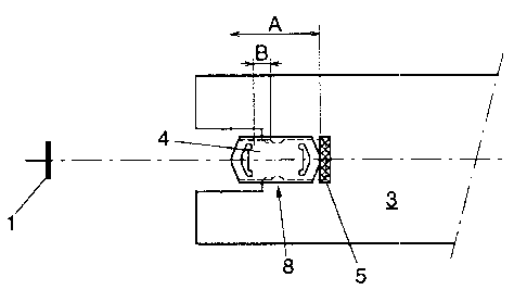
Figs la-b show a schematic top plan view and a longitudinal
section, respectively, of a known ball cage with cage buffer
and associated rail element:
Figs 2a-b show a plan view and a section, respectively,
similar to Figs la-b, of the position in 'which the rail
element is in abutment with the cage buffer of the ball cage;
Figs 3a-b show a plan view and a section, respectively,
similar to Figs 1a-b, at the end of the extension movement of
the telescopic rail;
Figs 4a-6b show plan views and sections similar to
Figs la-3b of a ball cage comprising a two-part cage buffer
according to a first embodiment of the invention;
Figs 7a-b show a plan view and a side elevation,
respectively, of the buffer block according to Figs 4-6;
Figs Sa-b show a single-part cage buffer according to a
second embodiment of the invention.
Figs 1a-b show a section 7 connected for instance to an
extendable drawer, which section comprises a lug 1 bent over
from said section, which lug is disposed at a distance from
the schematically shown ball cage 3. Provided in the body of
the ball cage 3 is a U-shaped recess 8 whose lateral edges are
provided with barbs for retaining in position a plastic cage

4
buffer 2 slid onto the body 3. The rear of the cage buffer 2
is disposed against a lug 6 bent over from the body of the
ball cage 3. F indicates the direction of movement of the
section 7 in the direction of the ball cage 3. The cage buffer
2 projects slightly from the recessed side edge of the body 3
of the ball cage, as will appear from Fig. la.
As shown in Figs 2a-b, when the drawer connected to the
section 7 is fully extended, the bent lug 1 will abut against
the cage buffer 2, with the shock being taken up by that cage
buffer 2 and transmitted to the lug 6 benit over from the body
3 of the ball cage. The cage buffer 2 is solid and practically
immovable relative to the ball cage 3, so that any shock
damping action is obtained only by virtue of the choice of the
plastic material from which the cage buffer 2 is made. Fig. 3
is identical to Fig. 2.
A first embodiment of the ball cage according to the
invention is shown in Figs 4-7, Figs 4-6 corresponding to
Figs 1-3. As will appear from Fig. 4a, the cage buffer now
consists of a buffer member 4 and a stop member 5, which stop
member 5 is arranged in the U-shaped recess 8 and is in
abutment with the rear edge thereof which is disposed in the
plane of the body 3 of the ball cage, in other words, the bent
lug 6 is absent. The buffer member 4 compi:ises two spring
chambers 13 and is arranged in the U-shaped recess 8 in the
same manner as the cage buffer 2 by way of slots 10 provided
in the lateral edges of the buffer member 4 (see Fig. 7).

5
_ Along a portion of the length of the buffer member 4, the
bottom of the slot 10 is provided with a recessed portion 11
for receiving a projection 9 which forms an integral part of
the lateral edge of the U-shaped recess 8. Thus, the buffer
member 4 can move relative to the body 3 of the ball cage so
as to enable compression of the spring chamber 13 disposed
adjacent the stop member 5. The two end faces 12 of the buffer
member 4 are substantially trapezoidal in shape and inwards of
each trapezoidal end 12 there is provided a substantially
dumbbell-shaped spring chamber 13 having a maximum height 14.
The trapezoidal end 12 can be compressed over a distance equal
to the height 14 of the spring chamber 13, so that the total
spring travel of the buffer member 4 equals twice the
height 14.
In view of its possible compression, the buffer member 4
must project further from the recessed lateral edge of the
body 3 of the ball cage than is the case in the known cage
buffer 2 (see Fig. 4a). The total length A of the buffer
member 4 is therefore greater than the length D of the known
cage buffer (see Fig. la). The spring travel of buffer member
4 is indicated in Fig. 4a at B.
Fig. 5 shows the situation where lug 1 of section 7 abuts
against the end of buffer member 4, while Fig. 6 shows the
situation where buffer member 4 has been compressed over the
spring travel distance B and section 7 has reached its fully
extended position.

6
The buffer member 4 is made of a material selected on the
basis of its elastic properties, for instance polyurethane,
while the stop member 5 consists of a harder plastic material
such as nylon.
The second embodiment of the cage buffer according to the
invention as shown in Figs 8a-b is different from the first
embodiment in that the stop member 5' and the buffer member 4'
have been combined to form a single part, for instance by
forming one member made of one material onto the other member
made of a different material along the line of separation S by
injection moulding. In this cage buffer, only one spring
chamber 13' is present, having a maximum height 14' slightly
greater than the height 14 of a spring chamber 13 (see
Fig. 7a). In this case, the rear edge 15' of the recess 8' in
the body 3' of the ball cage is in abutment with the bottom of
the slot 16' provided in the stop member .'~'. For the sake of
clarity, like parts in Figs 7 and 8 are indicated by like
reference characters, those in Fig. 8 being provided with an
accent.
Both embodiments of the cage buffer exhibit eminent
resistance in shock tests in which a drawer is loaded, for
instance up to its maximum bearing capacity of 100 kg, and
applied to the cage buffer at least 15 times at a speed of 1 m
per second, as well as in life tests in which the cage buffer
must resist a shock load of a drawer which is loaded up to 200
of its maximum bearing capacity and pulled against the cage
buffer 15,000 times from a distance of 5 cm.

Representative Drawing
A single figure which represents the drawing illustrating the invention.
Administrative Status

2024-08-01:As part of the Next Generation Patents (NGP) transition, the Canadian Patents Database (CPD) now contains a more detailed Event History, which replicates the Event Log of our new back-office solution.

Please note that "Inactive:" events refers to events no longer in use in our new back-office solution.

For a clearer understanding of the status of the application/patent presented on this page, the site Disclaimer , as well as the definitions for Patent , Event History , Maintenance Fee  and Payment History  should be consulted.

Event History

Description Date
Inactive: IPC expired 2017-01-01
Inactive: Reversal of expired status 2012-12-02
Time Limit for Reversal Expired 2011-11-26
Letter Sent 2010-11-26
Inactive: IPC from MCD 2006-03-11
Grant by Issuance 2002-03-19
Inactive: Cover page published 2002-03-18
Pre-grant 2001-12-20
Inactive: Final fee received 2001-12-20
Letter Sent 2001-06-27
Notice of Allowance is Issued 2001-06-27
Inactive: Approved for allowance (AFA) 2001-06-11
Amendment Received - Voluntary Amendment 1998-11-05
Inactive: Application prosecuted on TS as of Log entry date 1998-10-16
Inactive: RFE acknowledged - Prior art enquiry 1998-10-16
Inactive: Status info is complete as of Log entry date 1998-10-16
All Requirements for Examination Determined Compliant 1998-09-25
Request for Examination Requirements Determined Compliant 1998-09-25
Application Published (Open to Public Inspection) 1992-05-27

Abandonment History

There is no abandonment history.

Maintenance Fee

The last payment was received on 2001-08-22

Note : If the full payment has not been received on or before the date indicated, a further fee may be required which may be one of the following

  • the reinstatement fee;
  • the late payment fee; or
  • additional fee to reverse deemed expiry.

Patent fees are adjusted on the 1st of January every year. The amounts above are the current amounts if received by December 31 of the current year.
Please refer to the CIPO Patent Fees web page to see all current fee amounts.

Owners on Record

Note: Records showing the ownership history in alphabetical order.

Current Owners on Record
THOMAS REGOUT N.V.
Past Owners on Record
HENDRICUS TADEUSZ WOJCIK
Past Owners that do not appear in the "Owners on Record" listing will appear in other documentation within the application.
Documents

To view selected files, please enter reCAPTCHA code :


To view images, click a link in the Document Description column (Temporarily unavailable). To download the documents, select one or more checkboxes in the first column and then click the "Download Selected in PDF format (Zip Archive)" or the "Download Selected as Single PDF" button.

List of published and non-published patent-specific documents on the CPD .

If you have any difficulty accessing content, you can call the Client Service Centre at 1-866-997-1936 or send them an e-mail at CIPO Client Service Centre.

({010=All Documents, 020=As Filed, 030=As Open to Public Inspection, 040=At Issuance, 050=Examination, 060=Incoming Correspondence, 070=Miscellaneous, 080=Outgoing Correspondence, 090=Payment})


Document
Description 
Date
(yyyy-mm-dd) 
Number of pages   Size of Image (KB) 
Abstract 1994-02-25 1 10
Claims 1994-02-25 2 33
Claims 1998-11-04 2 63
Representative drawing 1999-04-27 1 3
Description 1994-02-25 6 261
Drawings 1994-02-25 4 63
Representative drawing 2002-02-20 1 5
Reminder - Request for Examination 1998-07-27 1 129
Acknowledgement of Request for Examination 1998-10-15 1 172
Commissioner's Notice - Application Found Allowable 2001-06-26 1 165
Maintenance Fee Notice 2011-01-06 1 171
Correspondence 2001-12-19 1 34
Fees 1996-10-06 1 50
Fees 1995-08-28 1 46
Fees 1994-10-17 1 43
Fees 1993-10-03 1 22