Note: Descriptions are shown in the official language in which they were submitted.
2~56323
1 BACKGROUND OF THE INVENTION
(l) Field of the Invention
The present invention relates to a
superconducting magnet coil, an insulating layer thereof
and a curable resin composition used in said
superconducting magnet coil.
(2) Description of the Prior Art
In a superconducting magnet coil used, by
being dipped in liquid helium, in linear motor cars,
superconducting electromagnetic propulsion vessels,
nuclear fusion reactors, superconducting generators,
MRI, pion applicators (for therapy), electron
microscopes, energy storage apparatuses, etc., the
superconducting wires contained in the coil cause a
temperature increase incurred by frictional heat or the
like when the superconducting wires are moved by an
electromagnetic force or a mechanical force. As a
result, the magnet may shift from a superconducting
state to a state of normal conduction. This phenomenon
is called a quench phenomenon. Hence, it is conducted
in some cases to fill the gap between the wires of the
coil with a resin such as epoxy resins or the like to
fix the wires.
The resin such as epoxy resins or the like,
used for filling the coil gap usually has a thermal
-- 1 -- ~
2~!56323
1 shrinkage factor of 1.8-3.0% when cooled from the glass
transition temperature to a liquid helium temperature,
i.e. 4.2 K. Meanwhile, the superconducting wires have a
thermal shrinkage factor of about 0.3-0.4% under the
same condition. As Y. Iwasa et al. describe in
Cryogenics Vol. ?5, pp. 304-326 (1985), when a
superconducting magnet coil comprising superconducting
wires and a resin used for filling the gap between the
wires is cooled to a liquid helium temperature, i.e. 4.2
K, a residual thermal stress appears due to the
difference in thermal shrinkage factor between the
superconducting wires and the resin. As a result,
microcracks of several microns appear in the resin, a
temperature increase of several degrees is induced at
the peripheries of the microcracks due to the releasing
energy of the residual thermal stress of the resin, and
the superconducting wires show a sharp rise in
resistance. Finally, the superconducting magnet coil
shifts from a superconducting state to a state of normal
conduction and causes an undesirable phenomenon called
"quench". Further, at the liquid helium temperature
(4.2 K), the impregnant resin such as epoxy resins or
the like gets very brittle and produces microcracks of
several microns, due to an electromagnetic force or a
mechanical force. The releasing energy from the
microcracks gives rise to a temperature increase of
several degrees at the peripheries of the microcracks.
Thus, the superconducting wires show a sha~ rise in
2~56323
1 resistance, the superconducting magnet coil shifts from
a superconducting state to a state of normal conduction
and disadvantageously causes quench.
SUMMARY OF THE l-Nv~N~lION
The present invention has been made in view of
the above situation. The objects of the present
invention are to provide a superconducting magnet coil
which is resistant to microcrack generation of
impregnant resin and causes substantially no quench
during operation; an insulating layer thereof; and a
curable resin composition used in said superconducting
magnet coil.
The objects of the present invention can be
achieved by using, as a resin for impregnation of
superconducting magnet coil, a curable resin composition
capable of giving a cured product having a thermal
shrinkage factor of 1.5-0.3% when cooled from the glass
transition temperature to a liquid helium temperature,
i.e. 4.2 K, a bend-breaking strain of 2.9-3.9% at 4.2 K
and a modulus of 500-1,000 kg/mm2 at 4.2 K, particularly
a cured product having a thermal shrinkage factor of
1.0-0.3% when cooled from the glass transition
temperature to a liquid helium temperature, i.e. 4.2 K,
a bend-breaking strain of 2.9-3.9% at 4.2 K and a
modulus of 500-1,000 kg/mm2 at 4.2 K.
The present invention is briefly described as
follows. The first aspect of the present invention
2~S6323
1 relates to a superconducting magnet coil which is
impregnated with a curable resin composition capable of
giving a cured product having a thermal shrinkage factor
of 1.5-0.3% when cooled from the glass transition
temperature to a liquid helium temperature, i.e. 4.2 K,
a bend-breaking strain of 2.9-3.9% at 4.2 K and a
modulus of 500-1,000 kg/mm2 at 4.2 K, particularly a
cured product having a thermal shrinkage factor of 1.0-
0.3% when cooled from the glass transition temperature
to a liquid helium temperature, i.e. 4.2 K, a bend-
breaking strain of 2.9-3.9% at 4.2 K and a modulus of
500-1,000 kg/mm2 at 4.2 K.
The second aspect of the present invention
relates to a resin used for impregnation of
superconducting magnet coil, that is, a curable resin
composition capable of giving a cured product having a
thermal shrinkage factor of 1.5-0.3% when cooled from
the glass transition temperature to a liquid helium
temperature, i.e. 4.2 K, a bend-breaking strain of 2.9-
4.5% at 4.2 K and a modulus of 500-1,000 kg/mm2 at 4.2
K, particularly a cured product having a thermal
shrinkage factor of 1.0-0.3% when cooled from the glass
transition temperature to a liquid helium temperature,
i.e. 4.2 K, a bend-breaking strain of 2.9-3.9% at 4.2 K
and a modulus of 500-1,000 kg/mm2 at 4.2 K.
The third aspect of the present invention
relates to a process for producing a superconducting
magnet coil which comprises a coil of superconducting
2(~56323
1 wire and a cured product of a curable resin composition
with which the coil has been impregnated, which process
comprises the steps of:
(a) winding a superconducting wire to form a
coil,
(b) filling the gap between the super-
conductors of the coil with a curable resin composition
having a viscosity of 0.01-10 poises at the time of
filling to obtain a curable-resin-composition-
impregnated coil, and
(c) heating the curable-resin-composition-
impregnated coil to cure the composition so as to give a
cured product having a thermal shrinkage factor of 1.5-
0.3% when cooled from the glass transition temperature
to a liquid helium temperature, i.e. 4.2 K, a bend-
breaking strain of 2.9-3.9% at 4.2 K and a modulus of
S00-1,000 kg/mm2 at 4.2 K, particularly a cured product
having a thermal shrinkage factor of 1.0-0.3% when
cooled from the glass transition temperature to a liquid
helium temperature, i.e. 4.2 K, a bend-breaking strain
of 2.9-3.9% at 4.2 K and a modulus of 500-1,000 kg/mm2
at 4.2 K.
The fourth aspect of the present invention
relates to an insulating layer of superconducting magnet
coil, which is obtained by impregnation of a coil of
superconducting wire with a curable resin composition
and curing of the resin composition, said resin
composition being capable of giving a cured product
2~5S323
1 having a thermal shrinkage factor of 1.5-0.3% when
cooled from the glass transition temperature to a liquid
helium temperature, i.e. 4.2 K, a bend-breaking strain
of 2.9-4.5% at 4.2 K and a modulus of 500-l.000 kgjmm2
5 at 4.2 K, particularly a cured product having a thermal
shrinkage factor of 1.0-0.3% when cooled from the glass
transition temperature to a liquid helium temperature,
i.e. 4.2 K, a bend-breaking strain of 2.9-4.5% at 4.2 K
and a modulus of 500-l,000 kg/mm2 at 4.2 K.
According to the present invention, there are
provided:
a superconducting magnet coil which comprises
a coil of superconducting wire and a cured product of a
curable resin composition with which the coil has been
15 impregnated, the cured product having a thermal
shrinkage factor of 1.5-0.3% when cooled from the glass
transition temperature to 4.2 K, a bend-breaking strain
of 2.9-3.9~, preferably 3.2-3.9% at 4.2 K and a modulus
of 500-1,000 kg/mm2 at 4.2 K;
a superconducting magnet coil which comprises
a coil of superconducting wire and a cured product of a
curable resin composition with which the coil has been
impregnated, the cured product undergoing a thermal
stress of 0-lO kg/mm2 when cooled from the glass
25 transition temperature to 4.2 K and resisting to quench
during superconducting operation;
a curable resin composition which gives a
cured product having a thermal shrinkage factor of 1.5-
2~56323
1 0.3%, preferably 1.0-0.3% when cooled from the glass
transition temperature to 4.2 K, a bend-breaking strain
of 2.9-3.9% at 4.2 K and a modulus of 500-1,000 kg/mm2
at 4.2 K;
a process for producing the superconducting
magnet coil which comprises the steps of:
(a) winding a superconducting wire to form a coil,
(b) impregnating the coil with a curable resin
composition having a viscosity of 0.01-10 poises at the
time of filling, with, for example, a curable resin
composition comprising (i) at least one epoxy resin
selected from the group consisting of diglycidyl ether
of bisphenol A, diglycidyl ether of bisphenol F and
diglycidyl ether of bisphenol AF, all having a number-
average molecular weight of 350-1,000, (ii) a
flexibilizer and (iii) a curing catalyst, so as to fill
the gap between the superconductors of the coil with the
curable resin composition to obtain a curable-resin-
composition-imprgnated coil, and
(c) heating the curable-resin-composition-
impregnated coil to cure the composition to allow the
cured product of the composition to have a thermal
shrinkage factor of 1.5-0.3%, preferably 1.0-0.3% when
cooled from the glass transition temperature to 4.2 K, a
bend-breaking strain of 2.9-3.9~ at 4.2 K and a modulus
of 500-1,000 kg/mm2 at 4.2 K,
preferably, the step (b) including the step of
covering the outer surface of the coil with a release
2C5S323
1 film or a perforated film, placing the film-covered coil
in a mold, and effecting vacuum impregnation, and if
necessary pressure impregnation, of the coil with the
curable resin composition,
preferably, the step (c) including the step of
curing the composition under pressure, and if necessary
further comprising the step of clamping the curable-
resin-composition-impregnated coil before the step of
curing;
a superconducting magnet coil which comprises:
(a) a coil of a composite superconductor
comprising a plurality of thin superconducting wires and
a stabilizer selected from the group consisting of
copper and aluminum which is thermally or electrically
contacted with the wires, and
(b) a cured product of a curable resin composition
with which the coil has been impregnated,
the cured product having a thermal shrinkage
factor of 1.5-0.3% when cooled from the glass transition
temperature to 4.2 K, a bend-breaking strain of 2.9-3.9%
at 4.2 K and a modulus of 500-1,000 kg/mm2 at 4.2 K;
a superconducting magnet coil which comprises:
(a) a coil of a composite superconductor
comprising a plurality of thin superconducting wires and
a stabilizer seleccted from the group consisting of
copper and aluminum which is thermally or electrically
contacted with the wires, and
(b) a cured product of a curable resin composition
8 --
2C5S323
with which the coil has been impregnated,
the cured product undergoning a thermal stress
of 0-10 kg/mm2 when cooled from the glass transition
temperature to 4.2 K and resisting to quench during
superconducting operation;
a process for producing the superconducting
magnet coil which comprises the steps of:
(a) winding a composite superconductor comprising
a plurality of thin superconducting wires and a
stabilizer selected from the group consisting of copper
and aluminum which is thermally or electrically
contacted with the wires to form a coil,
(b) filling the gap between the composite
superconductors of the coil with a curable resin
compostion to obtain a curable-resin-composition-
impregnated coil, and
(c) heating the curable-resin-composition-
impregnated coil to cure the composition,
the step (a) including the step of subjecting
20 the composite superconductor to surface treatment with a
coupling agent before winding the composite super-
conductor; and
an insulating layer of superconducting magnet
coil which comprises:
(a) a coil of a composite superconductor
comprising a plurality of thin superconducting wires and
a stabilizer selected from the group consisitng of
copper and aluminum which is thermally or electrically
Z~56323
-
1 contacted with the wires, and
(b) a cured product of a curable resin composition
with which the coil has been impregnated,
the cured product having a thermal shrinkage
factor of 1.5-0.3% when cooled from the glass transition
temperature to 4.2 K, a bend-breaking strain of 2.9-3.9%
at 4.2 K and a modulus of 500-1,000 kg/mm2 at 4.2 K.
BRIEF DESCRIPTION OF THE DRAWINGS
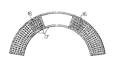
Fig. l is a perspective view of a race track-
shaped superconducting magnet coil. The numeral 1 is around superconducting magnet coil.
Fig. 2 is a cross-sectional view of the coil
of Fig. l when cut at an A-A' line.
Fig. 3 is a fragmentary enlarged view of Fig.
2 of a conventional race track-shaped superconducting
magnet coil.
Fig. 4 is a perspective view of a saddle-
shaped superconducting magnet coil.
Fig. 5 is a cross-sectional view of the coil
of Fig. 4 when cut at a B-B' line.
DETAILED DESCRIPTION OF THE INVENTION
The curable resin composition according to the
present invention can also be preferably used in
switches for permanent current which are required in
superconducting magnet coils for linear motor cars, MRI,
energy storage and nuclear fusions.
-- 10 --
2~SS323
-
1 The superconducting wire used in the present
invention has no particular restriction and can be any
wire as long as it has superconductivity. There can be
mentioned, for example, alloy superconductors such as
Nb-Ti and the like; intermetallic compound super-
conductors such as Nb3Sn, Nb3Al, V3Ga and the like; and
oxide superconductors such as LaBaCuO, YBaCuO and the
like. Ordinarily, the superconducting wire has a
composite structure comprising (a) the above super-
conductor and (2) a metal of normal conduction such asCu, cupro-nickel (CuNi), CuNi-Cu, Al or the like. That
is, the superconducting wire includes an ultrafine
multiconductor wire obtained by embedding a large number
of thin filament-like superconducting wires into a metal
of normal conduction as a matrix, a straight twisted
wire obtained by binding a large number of super-
conducting material wires into a straight bundle and
twisting the bundle with the straightness being
maintained, a straight wire obtained by embedding a
straight superconducting material wire into a straight
normal conductor, and an internal cooling type conductor
having inside a passage for cooling medium.
The resin for impregnation of superconducting
magnet coil, used in the present invention has no
particular restriction and can be any resin as long as
it can give a cured product having a thermal shrinkage
factor of 1.5-0.3% when cooled from the glass transition
temperature to a liquid helium temperature, i.e. 4.2 K,
-- 11 --
2(~5~323
1 a bend-breaking strain of 2.9-3.9% at 4.2 K and a
modulus of 500-l,000 kg/mm2 at 4.2 K, particularly a
cured product having a thermal shrinkage factor of l.0-
0.3% when cooled from the glass transition temperature
to a liquid helium temperature, i.e. 4.2 K, a bend-
breaking strain of 2.9-3.9% at 4.2 K and a modulus of
500-l,000 kg/mm2 at 4.2 K.
When the cured product of the resin has a
thermal shrinkage factor larger than 1.5% and a modulus
larger than 1,000 kg/mm2, the stress applied to the
superconducting magnet during the superconducting
operation surpasses the strength of the cured product.
As a result, the cured product generates cracks, and
quench occurs due to the releasing energy of the stress.
15 When the cured product has a thermal shrinkage factor
smaller than 0.3%, the stress applied to the super-
conducting magnet during the superconducting operation
surpasses the strength of the cured product due to the
difference in thermal shrinkage factor between the cured
20 product and the superconductor of the magnet. As a
result, the cured product generates cracks, and quench
tends to occur due to the releasing energy of the
stress. When the modulus is smaller than 500 kg/mm2,
the glass transition temperature tends to be lower than
room temperature and, when the superconducting magnet
has been returned to room temperature, the cured product
generates cracks due to the low strength; when the
magnet is recooled to 4.2 K and reoperated, the cracks
- 12 -
2(~56323
1 become a nucleus of further crack generation and the
superconducting magnet causes quench. When the bend-
breaking strain is smaller than 2.9%, the cured product
has low adhesion to the superconductor and, after the
cooling or during the operation of the superconducting
magnet, peeling takes place between the superconductor
and the cured product. As a result, thermal conduc-
tivity between them is reduced, even slight cracking
invites temperature increase, and the superconducting
10 magnet tends to incur quench.
As the method for increasing the bend-breaking
strain of a thermosetting resin, that is, for toughening
a thermosetting resin, there are a number of methods.
In the case of an epoxy resin, for example, there are
(1) a method of subjecting an epoxy resin to preliminary
polymerization to obtain an epoxy resin having a higher
molecular weight between crosslinked sites, (2) a method
of adding a flexibilizer (e.g. polyol, phenoxy resin) to
an epoxy resin to increase the specific volume of the
20 latter, (3) a method of introducing a soft molecular
skeleton into an epoxy resin by using a curing agent
such as elastomer-modified epoxy resins, long-chain
epoxy resins, long-chain amines, acid anhydrides,
mercaptans or the like, (4) a method of using an
25 internal plasticizer such as branched epoxy resins,
polyamide-amines, dodecyl succinic anhydrides or the
like, (S) a method of using, in combination with an
epoxy resin, a monofunctional epoxy resin to give rise
Z(~56323
.
1 to internal plasticization, (6) a method of using an
epoxy resin as a main component and a curing agent in
proportions deviating from the stoichiometric amounts to
give rise to internal plasticization, (7) a method of
adding a plasticizer (e.g. phthalic acid ester) to give
rise to external plasticization, (8) a method of
dispersing butadiene rubber particles, silicone rubber
particles or the like in an epoxy resin to form an
islands-in-a-sea structure, (9) a method of introducing,
into an epoxy resin, an acrylic resin, an urethane
resin, a polycaprolactone, an unsaturated polyester or
the like to form an interpenetrating network structure,
i.e. an IPN structure, (lO) a method of adding, to an
epoxy resin, a polyether having a molecular weight of
1,000-5,000 to form a microvoid structure, and so forth.
Of these methods, the methods (l) and (2) are preferable
in view of the low thermal shrinkage and high toughness
of the improved epoxy resin.
Specific examples of the improved epoxy resin
obtained according to the above methods, are an epoxy
resin obtained by curing an epoxy resin of high
molecular weight with an acid anhydride, an epoxy resin
obtained by curing an epoxy resin of high molecular
weight with a catalyst alone, an epoxy resin obtained by
adding a flexibilizer to an epoxy resin and curing the
resin with an acid anhydride, an epoxy resin obtained by
adding a flexibilizer to an epoxy resin and curing the
resin with a catalyst alone, and a maleimide resin
- 14 -
2C~SS323
.
1 obtained by adding a flexibilizer.
The epoxy resin usable in the present
invention can be any epoxy resin as long as it has at
least two epoxy groups in the molecule. Such an epoxy
resin includes, for example, bifunctional epoxy resins
such as diglycidyl ether of bisphenol A, diglycidyl
ether of bisphenol F, diglycidyl ether of bisphenol AF,
diglycidyl ether of bisphenol AD, diglycidyl ether of
hydrogenated bisphenol A, diglycidyl ether of 2,2-(4-
hydroxyphenyl)nonadecane, 4,4'-bis(2,3-epoxypropyl)
diphenyl ether, 3,4-epoxycyclohexylmethyl (3,4-
epoxy)cyclohexanecarboxylate, 4-(1,2-epoxypropyl)-1,2-
epoxycyclohexane, 2-(3,4-epoxy)cyclohexyl-5,5-spiro(3,4-
epoxy)-cyclohexane-m-dioxane, 3,4-epoxy-6-methyl-
cyclohexylmethyl-4-epoxy-6-methylcyclohexanecarboxylate,
butadiene-modified epoxy resin, urethane-modified epoxy
resin, thiol-modified epoxy resin, diglycidyl ether of
diethylene glycol, diglycidyl ether of triethylene
glycol, diglycidyl ether of polyethylene glycol,
diglycidyl ether of polypropylene glycol, diglycidyl
ether of 1,4-butanediol, diglycidyl ether of neopentyl
glycol, diglycidyl ether of propylene oxide adduct of
bisphenol A, diglycidyl ether of ethylene oxide adduct
of bisppenol A, and the like; trifunctional epoxy resins
such as tris[p-(2,3-epoxypropoxy)phenyl]methane, 1,1,3-
tris[p-(2,3-epoxypopoxy)phenyl]butane and the like; and
polyfunctional epoxy resins such as glycidylamine (e.g.
tetraglycidyldiaminodiphenylmethane, triglycidyl-p-
ZC56323
1 aminophenol, triglycidyl-m-aminophenol, diglycidylamine,
tetraglycidyl-m-xylylenediamine, tetraglycidyl-bis-
aminomethylcyclohexane), phenolic novolac type epoxy
resin, cresol type epoxy resin and the like. It is also
5 possible to use a polyfunctional epoxy resin obtained by
reacting epichlorohydrin with at least two polyhydric
phenols selected from (a) bis(4-hydroxyphenyl)methane,
(b) bis(4-hydroxyphenyl)ethane, (c) bis(4-hydroxy-
phenyl)propane, (d) tris(4-hydroxyphenyl)alkane and (e)
tetrakis(4-hydroxyphenyl)alkane, because the resin has a
low viscosity before curing and gives easy working.
Specific examples of tris(4-hydroxyphenyl)alkane are
tris(4-hydroxyphenyl)methane, tris(4-hydroxyphenyl)-
ethane, tris(4-hydroxyphenyl)propane, tris(4-
15 hydroxyphenyl)butane, tris(4-hydroxyphenyl)hexane,
tris(4-hydroxyphenyl)heptane, tris(4-hydroxyphenyl)-
octane, tris(4-hydroxyphenyl)nonane, etc. There can
also be used tris(4-hydroxyphenyl)alkane derivatives
such as tris(4-hydroxydimethylphenyl)methane and the
20 like.
Specific examples of tetrakis(4-hydroxy-
phenyl)alkane are tetrakis(4-hydroxyphenyl)methane,
tetrakis(4-hydroxyphenyl)ethane, tetrakis(4-hydroxy-
phenyl)propane, tetrakis(4-hydroxyphenyl)butane, tetra-
25 kis(4-hydroxyphenyl)hexane, tetrakis(4-hydroxyphenyl)
heptane, tetrakis(4-hydroxyphenyl)octane, tetrakis(4-
hydroxyphenyl)nonane and the like. It is also possible
to use tetrakis(4-hydroxyphenyl)alkane derivatives such
- 16 -
2C~6323
1 as tetrakis(4-hydroxydimethylphenyl)methane and the
like. Of these, useful are diglycidyl ether of
bisphenol A, diglycidyl ether of bisphenol F, diglycidyl
ether of bisphenol AF, diglycidyl ether of bisphenol AD,
and diglycidyl ethers of higher-molecular-weight
bisphenols A, F, AF and AD, because they have a low
thermal shrinkage factor. Particularly preferable are
diglycidyl ethers of higher-molecular-weight bisphenols
A, F, AF and AD wherein the n of the repeating unit has
a value of 2-18. The above polyfunctinal epoxy resins
may be used in combination of two or more. If
necessary, the polyfunctional epoxy resin may be mixed
with a monofunctional epoxy resin such as butyl glycidyl
ether, styrene oxide, phenyl glycidyl ether, allyl
glycidyl ether or the like in order to obtain a lower
viscosity. However, the amount of the monofunctional
epoxy resin added should be small because, in general,
the monofunctional epoxy resin has an effect for
viscosity reduction but brings about increase in thermal
shrinkage factor.
The acid anhydride used in the present
invention has no particular restriction and can be any
ordinary acid anhydride. Such an acid anhydride
includes methylhexahydrophthalic anhydride,
hexahydrophthalic anhydride, methyltetrahydrophthalic
anhydride, tetrahydrophthalic anhydride, nadic
anhydride, methylnadic anhydride, dodecylsuccinic
anhydride, succinic anhydride, octadecylsuccinic
- 17 -
Z(~56323
1 anhydride, maleic anhydride, benzophenonetetracarboxylic
anhydride, ethylene glycol bis(anhydrotrimellitate),
glycerol tris(anhydrotrimellitate), etc. They can be
used alone or in combination of two or more.
The maleimide used in the present invention
can be any maleimide as long as it is an unsaturated
imide containing in the molecule the group having the
formula (I),
/ CO \
CO (I)
wherein D is a bivalent group containing a carbon-carbon
double bond. Such an unsaturated imide includes, for
example, bifunctional maleimides such as N,N'-ethylene-
bismaleimide, N,N'-hexamethylene-bis-maleimide, N,N'-
dodecamethylene-bismaleimide, N,N'-m-xylylene-
bismaleimide, N,N'-p-xylylene-bismaleimide, N,N'-1,3-
bismethylenecyclohexane-bismaleimide. N,N'-1,4-
bismethylenecyclohexane-bismaleimide, N,N'-2,4-
tolylene-bismaleimide, N,N'-2,6-tolylene-bismaleimide,
N,N'-3,3'-diphenylmethane-bismaleimide, N,N'-(3-ethyl)-
3,3'-diphenylmethane-bismaleimide, N,N'-(3,3'-dimethyl)-
3,3'-diphenylmethane-bismaleimide, N,N'-(3,3'-diethyl)-
3,3'-diphenylmethane-bismaleimide, N,N'-(3,3'-dichloro)-
3,3'-diphenylmethane-bismaleimide, N,N'-4,4'-
diphenylmethane-bismaleimide, N,N'-(3-ethyl)-4,4'-
- 18 -
2~5S323
1 diphenylmethane-bismaleimide, N,N'-(3,3'-dimethyl)-4,4'-
diphenylmethane-bismaleimide, N,N'-(3,3'-diethyl)-4,4'-
diphenylmethane-bismaleimide, N,N'-(3,3'-dichloro)-4,4'-
diphenylmethane-bismaleimide, N,N'-3,3'-diphenylsulfone-
bismaleimide, N,N'-4,4'-diphenylsulfone-bismaleimide,
N,N'-3,3'-diphenylsulfide-bismaleimide, N,N'-4,4'-
diphenylsulfide-bismaleimide, N,N'-p-benzophenone-bis-
maleimide, N,N'-4,4'-diphenylethane-bismaleimide, N,N'-
4,4'-diphenylether-bismaleimide, N,N'-(methylene-
ditetrahydrophenyl)bismaleimide, N,N'-tolidine-
bismaleimide, N,N'-isophorone-bismaleimide, N,N'-p-
diphenyldimethylsilyl-bismaleimide, N,N'-4,4'-
diphenylpropane-bismaleimide, N,N'-naphthalene-bis-
maleimide, N,N'-p-phenylene-bismaleimide, N,N'-m-
phenylene-bismaleimide, N,N'-4,4'-(1,1'-diphenyl-
cyclohexane)bismaleimide, N,N'-3,5-(1,2,4-triazole)-
bismaleimide, N,N'-pyridine-2,6-diyl-bismaleimide, N,N'-
5-methoxy-1,3-phenylene-bismaleimide, 1,2-bis(2-
maleimideethoxy)ethane, 1,3-bis(3-maleimidepropoxy)-
propane, N,N'-4,4'-diphenylmethane-bisdimethylmaleimide,
N,N'-hexamethylene-bisdimethylmaleimide, N,N'-4,4'-
(diphenylether)bisdimethylmaleimide, N,N'-4,4'-
(diphenylsulfone)bisdimethylmaleimide, N,N'-bismaleimide
of 4,4'-diaminotriphenyl phosphate, N,N'-bismaleimide of
2,2'-bis[4-(4-aminophenoxy)phenyl]propane, N,N'-
bismaleimide of 2,2'-bis~4-(4-aminophenoxy)phenyl-
methane, N,N'-bismaleimide of 2,2'-bis[4-(4-amino-
phenoxy)phenylethane and the like; polyfunctional
-- 19 --
2~5S323
1 maleimides obtained by reacting maleic anhydride with an
aniline-formalin reaction product (a polyamine
compound), 3,4,4'-triaminodiphenylmethane, triamino-
phenol or the like; monomaleimides such as phenyl-
maleimide, tolylmaleimide, xylylmaleimide and the like;various citraconimides; and various itaconimides. These
unsaturated imides can be used by adding to an epoxy
resin, or can be cured with a diallylphenol compound, an
allylphenol compound or a diamine compound or with a
catalyst alone.
The flexibilizer used in the present invention
can be any flexibility-imparting agent as long as it can
impart flexibility, toughness and adhesion. Such a
flexibilizer includes, for example, diglycidyl ether of
linoleic acid dimer, diglycidyl ether of polyethylene
glycol, diglycidyl ether of polypropylene glycol,
diglycinyl ether of alkylene oxide adduct of bisphenol
A, urethane-modified epoxy resin, polybutadiene-modified
epoxy resin, polyethylene glycol, polypropylene glycol,
polyol (e.g. hydroxyl group-terminated polyester),
polybutadiene, alkylene oxide adduct of bisphenol A,
polythiol, urethane prepolymer, polycarboxyl compound,
phenoxy resin and polycaprolactone. The flexibilizer
may be a low viscosity compound such as caprolactone or
the like, which is polymerized at the time of curing of
the impregnant resin and thereby exhibits flexibility.
Of the above flexibilizers, a polyol, a phenoxy resin or
a polycaprolactone is preferable in view of the high
- 20 -
2(~5S323
-
1 toughness and low thermal expansion.
The catalyst used in the present invention has
no particular restriction and can be any compound as
long as it has an action of accelerating the reaction of
an epoxy resin or a maleimide. Such a compound include,
for example, tertiary amines such as trimethylamine,
triethylamine, tetramethylbutanediamine, triethylene-
diamine and the like; amines such as dimethylamino-
ethanol, dimethylaminopentanol, tris(dimethylamino-
methyl)phenol, N-methylmorpholine and the like;
quaternary ammonium salts such as cetyltrimethylammonium
bromide, cetyltrimethylammonium chloride, cetyl-
trimethyl-ammonium iodide, dodecyltrimethylammonium
bromide, dodecyltri-methylammonium chloride, dodecyl-
trimethylammonium iodide, benzyldimethyltetradecyl-
ammonium chloride, benzyldimethyltetradecylammonium
bromide, allyldodecyltrimethylammonium bromide,
benzyldimethylstearylammonium bromide, stearyltrimethyl-
ammonium chloride, benzyldimethyltetradecylammonium
acetylate and the like; imidazoles such as 2-methyl-
imidazole, 2-ethylimidazole, 2-undecylimidazole, 2-
heptadecylimidazole, 2-methyl-4-ethylimidazole, 1-
butylimidazole, l-propyl-2-methylimidazole, 1-benzyl-2-
methylimidazole, l-cycanoethyl-2-phenylimidazole, 1-
cyanoethyl-2-methylimidazole, 1-cyanoethyl-2-undecyl-
imidazole, l-azine-2-methylimidazole, 1-azine-2-undecyl-
imidazole and the like; microcapsules of amines or
imidazoles; metal salts between (a) an amine or
- 21 -
2(~5S323
1 imidazole and (b) zinc octanoate, cobalt or the like;
1,8-diaza-bicyclo[5.4.0]-undecene-7; N-methyl-
piperazine; tetramethylbutylguanidine; amine tetraphenyl
borates such as triethylammonium tetraphenyl borate, 2-
ethyl-4-methyltetraphenyl borate, 1,8-diazabicyclo-
[5.4.0]-undecene-7-tetraphenyl borate and the like;
triphenylphosphine; triphenylphosphonium tetraphenyl
borate; aluminum trialkylacetoacetates; aluminum
trisacetylacetoacetate; aluminum alcoholates; aluminum
acylates; sodium alcoholates; boron trifluoride;
complexes between boron trifluoride and an amine or
imidazole; diphenyliodonium salt of HAsF6; aliphatic
sulfonium salts; amineimides obtained by reacting an
alkyl monocarboxylate with a hydrazine and a monoepoxy
compound; and metal (e.g. cobalt, manganese, iron) salts
of octylic acid or naphthenic acid. Of these,
particularly useful are quaternary ammonium salts, metal
salts between (a) an amine or imidazole and (b) zinc
octanoate, cobalt or the like, amine tetraphenyl
borates, complexes between boron trifluoride and an
amine or imidazole, diphenyliodonium salt of HAsF6,
aliphatic sulfonium salts, amineimides, microcapsules of
amines or imidazoles, etc. because they are relatively
stable at room temperature but can cause a reaction
easily at elevated temperatures, that is, they are a
latent curing catalyst. These curing agents are added
ordinarily in an amount of 0.1-10% by weight based on
the polyfunctional epoxy resin.
- 22 -
2~5S323
1 The stress which a superconducting magnet coil
undergoes during operation of the superconducting
magnet, includes a residual stress generated at the time
of production, a thermal stress applied during cooling
and an electromagnetic force applied during operation.
First, description is made on the thermal stress applied
to the cured resin of a superconducting magnet coil when
the coil after production is cooled to a liquid helium
temperature, i.e. 4.2 K.
The thermal stress ~ applied to the cured
resin of a superconducting magnet coil when the coil
after production is cooled to a liquid helium
temperature, i.e 4.2 K, can be represented by the
following formula:
~ = f T (R - s)E dT
wherein aR is a thermal expansion coefficient of the
cured resin; s is a thermal expansion coefficient of
the superconducting wire of the coil; E is a modulus of
the cured resin; and T is a curing temperature of the
resin used for obtaining the cured resin. Since the
modulus at temperatures above the glass transition
temperature Tg of the cured resin is smaller by about
two figures than the modulus at the glass transition
temperature Tg or below, the thermal stress applied to
the cured resin of superconducting magnet coil when the
coil after production is cooled to 4.2 K, can be
- 23 -
2~5S323
1 substantially represented by the following formula (1)
holding for when the coil after production is cooled
from the glass transition temperature of the cured resin
to 4.2 K:
4.2 K
a = ~ Tg (~R - ~s)E dT (1)
Now, the thermal stress a applied to the cured
resin of superconducting magnet coil when the coil after
production is cured to 4.2 K, is roughly calculated from
the above formula (1), using assumptions that the
thermal shrinkage factor of the cured resin when cooled
from the glass transition temperature Tg to 4.2 K be
2.0%, the thermal shrinkage factor of the super-
conducting wire of coil when cooled under the same
condition be 0.3% and the modulus of the cured resin be
1.000 kg/mm2 at 4.2 K; the rough calculation gives a
thermal stress a of about 17 kg/mm2. Meanwhile, cured
epoxy resins ordinarily have a strength of 17-20 kg/mm2
at 4.2 K. Accordingly, when the superconducting magnet
coil after production is cooled to a liquid helium
temperature, i.e. 4.2 K, the thermal stress a plus the
residual stress generated at the time of coil production
allow the cured resin to form microcracks of several
microns; the releasing energy of the stress of the cured
resin gives rise to a temperature increase of several
degress at the peripheries of the microcracks; as a
result, the resistance of the superconducting wire is
ZCSS3Z3
1 increased rapidly and there occurs a transition from a
superconducting state to a state of normal conduction,
i.e. a so-called quench phenomenon. In superconducting
magnet coils used in linear motor cars, MRI, etc.,
further an electromagnetic force of at least about 4
kg/mm2 is repeatedly applied during operation at 4.2 K.
This force plus the above-mentioned thermal stress and
residual stress allow the cured resin to form cracks,
and the releasing energy of the stress gives rise to a
10 ~uench phenomenon.
The thermal stress ~ applied to the cured
resin of superconducting magnet coil when the coil after
production is cooled to 4.2 K, is roughly calculated
from the formula (1), using a thermal shrinkage factor
Of the cured resin of 1.5% when cooled to 4.2 K and a
modulus of the cured resin of 1,000 kg/mm2 at 4.2 K; the
rough calculation gives a thermal stress a of about 12
kg/mm2. When an electromagnetic force of about 4 kg/mm2
is repeatedly applied to the above thermal stress during
20 operation at 4.2 K, the total stress becomes about 16
kg/mm2 .
Meanwhile, cured epoxy resins ordinarily have
a strength of 17-20 kg/mm2 at 4.2 K. Therefore, on
calculation, this strength can withstand the thermal
stress applied to the cured resin of superconducting
magnet coil when cooled to 4.2 K and the electromagnetic
force repeatedly applied to the cured resin during
operation.
- 25 -
2CSS323
1 Various impregnant resins of different thermal
shrinkage factors for superconducting magnet coil were
actually tested. The test indicated that when there is
used, as an impregnant resin for superconducting magnet
coil, a curable resin composition giving a cured product
having a thermal shrinkage factor of 1.5-0.3% when
cooled from the glass transition temperature to a liquid
helium temperature, i.e. 4.2 K, a bend-breaking strain
of 2.9-3.9% at 4.2 K and a modulus of 500-l,000 kg/mm2
at 4.2 K, the cured resin composition of superconducting
magnet coil generates no crack when cooled to a liquid
helium temperature, i.e. 4.2 K. The test also indicated
that no quench appears even in a superconducting
operation at 4.2 K wherein an electromagnetic force is
further applied.
When there is used, in particular, a
thermosetting resin composition giving a cured product
having a thermal shrinkage factor of 1.0-0.3% when
cooled from the glass transition temperature to a liquid
20 helium temperature, i.e. 4.2 K, a bend-breaking strain
of 2.9-3.9% and a modulus of 500-1,000 kg/mm2, quench
can be prevented with a large allowance even in a
superconducting operation at 4.2 K in which an
electromagnetic force is applied.
The present invention is hereinafter described
more specifically by way of Examples. However, the
present invention is by no means restricted to these
Examples.
- 26 -
2~5S323
1The determination of thermal shrinkage was
carried out with a thermal-mechanical analyzer (TMA)
having a sample-system provided in a cryostat which can
cool a sample to a very low temperature and a
measurement-system containing a differential transformer
with which the change of dimension of the sample
detected by a detecting rod can be measured.
The determination of bending properties was
carried out by immersing a sample in liquid helium using
a conventional bend test apparatus equipped with a
cryostat which can cool the sample to a very low
temperature. The size of the sample is 80 mm x 9 mm x 5
mm. The conditions of the determination were:
length between supports: 60 mm
15head speed: 2 mm/min
three-point bending.
In the Examples, the abbreviations used for
polyfunctional epoxy resins, flexibilizers, curing
catalysts and bismaleimides refer to the followings.
DER-332: diglycidyl ether of bisphenol A (epoxy
equivalent: 175)
EP-825: diglycidyl ether of bisphenol A (epoxy
equivalent: 178)
EP-827: diglycidyl ether of bisphenol A (epoxy
25equlvalent: 185)
EP-828: diglycidyl ether of bisphenol A (epoxy
equivalent: 189)
2(~5~323
EP-1001: diglycidyl ether of bisphenol A (epoxy
equivalent: 472)
EP-1002: diglycidyl ether of bisphenol A (epoxy
equivalent: 636)
EP-1003: diglycidyl ether of bisphenol A (epoxy
equivalent: 745)
EP-1055: diglycidyl ether of bisphenol A (epoxy
equivalent: 865)
EP-1004AF: diglycidyl ether of bisphenol A (epoxy
equivalent: 975)
EP-1007: diglycidyl ether of bisphenol A (epoxy
equivalent: 2006)
EP-1009: diglycidyl ether of bisphenol A (epoxy
equivalent: 2473)
EP-1010: diglycidyl ether of bisphenol A (epoxy
equivalent: 2785)
EP-807: diglycidyl ether of bisphenol F (epoxy
equivalent: 170)
PY-302-2: diglycidyl ether of bisphenol AF (epoxy
equivalent: 175)
DGEBAD: diglycidyl ether of bisphenol AD (epoxy
equivalent: 173)
HP-4032: 2,7-diglycidyl ether naphthalene (epoxy
equivalent: 150)
TGADPM: tetraglycidylaminodiphenylmethane
TTGmAP: tetraglycidyl-m-xylylenediamine
TGpAP: triglycidyl-p-aminophenol
TGmAP: triglycidyl-m-aminophenol
- 28 -
2056323
~ 1 CEL-2021: 3,4-epoxycyclohexylmethyl-(3,4-
epoxy)cyclohexane carboxylate (epoxy
equivalent: 138)
LS-108: bis-2,2'-{4,4'-[2-(2,3-epoxy)propoxy-3-butoxy-
propoxy]phenyl}propane (epoxy equivalent:
2100)
LS-402: bis-2,2'-{4,4'-[2-(2,3-epoxy)propoxy-3-butoxy-
propoxy]phenyl}propane (epoxy equivalent:
4600)
10 HN-5500: methylhexahydrophthalic anhydride (acid
anhydride equivalent: 168)
HN-2200: methyltetrahydrophthalic anhydride (acid
anhydride equivàlent: 166)
iPA-Na: sodium isopropylate
15 BTPP-K: tetraphenylborate of triphenylbutylphosphine
2E4MZ-K: tetraphenylborate of 2-ethyl-4-methylimidazole
2E4MZ-CN-K: tetraphenylborate of l-cyanoethyl-2-ethyl-
4-methylimidazole
TEA-K: tetraphenylborate of triethylamine
20 TPP-K: tetraphenylborate of triphenylphosphine
TPP: triphenylphosphine
IOZ: salt between 2-ethyl-4-methylimidazole and
zinc octanoate
DY063: alkyl alkoholate
25 YPH-201: an amineimide obtained by reacting an alkyl
monocarboxylate with a hydrazine and a
monoepoxy compound (YPH-201 manufactured by
Yuka Shell Epoxy K.K.)
- 29 -
* trade mark
.
205~3
. ,
1 CP-66: an aliphatic sulfonium salt of a protonic acid
(ADEKA OPTON CP-66 manufactured by ASA~I DENKA
KOGYO K.K.)
PX-4BT: tetrabutylphosphonium benzotriazolate
- 5 BF3-400: boron trifluoride salt of piperazine
BF3-100: boron trifluoride salt of triethylamine
2E4MZ-CNS: trimellitic acid salt of 2-ethyl-4-
methylimidazole
2E4MZ-OK: isocyanuric acid salt of 2-ethyl-4-
methylimidazole
MC-CllZ-AZINE: microcapsule of l-azine-2-
undecylimidazole
2E4MZ-CN: l-cycnoethyl-2-ethyl-4-methylimidazole
BDMTDAC: benzyldimethyltetradecylammonium chloride
15 BDMTDAI benzyldimethyltetradecylammonium iodide
HMBMI: N,N'-hexamethylene-bismaleimide
BMI: N,N'-4,4'-diphenylmethane-bismaleimide
DMBMI: N,N'-(3,3'-dimethyl)-4,4'-diphepylmethane-
bismaleimide
20 DAPPBMI: N,N'-bismaleimide of 2,2'-bis[4-(4-
aminophenoxy)phenyl]propane
PMI: N,N'-polymaleimide of a reaction product ~a
polyamine compound) between aniline and
formalin
25 DABPA: diallylbisphenol A
PPG: polypropylene glycol
KR: ~-caprolactone
- 30 -
* trade mark
2(~5S323
1 DGEAOBA; diglycidyl ether of an alkylene oxide adduct
of bisphenol A
PPO: phenoxy resin
CTBN: acrylonitrile-modified carboxyl group-
5 2 terminated polybutadiene rubber
2PZCN: l-cyanoethyl-2-phenylimidazole
LBO: lithium butoxide
PZ: pyridine
TEA: triethylamine
M2-100: benzylconium chloride
N-MM: N-methylmorpholine
MDI: 4,4'-diphenylmethane diisocyanate, equivalent:
125
LMDI: a mixture of MDI, an MDI derivative whose
isocyanate group has been converted to
carbodiimide and an MDI derivative whose
isocyanate groups have been converted to
carbodiimide, which mixture is liquid at room
temperature, equivalent: about 140
20 TDI: a mixture of 80~ of 2,4-tolylene diisocyanate
and 20~ of 2,6-tolylene diisocyanate,
equivalent: 87
KR2019: a resin obtained by condensation
polymerization of methylphenylsilicone
Examples 1-65 and Comparative Examples 1-6
Each of the resin compositions shown in Tables
1-1 to 1-13 was thoroughly stirred, placed in a mold,
- 31 -
2C5S323
1 and heat-cured under the curing conditions shown in
Tables 1-1 to 1-13. Each of the resulting cured
products was measured for thermal shrinkage factor when
cooled from the glass transition temperature to 4.2 K,
and the results are shown in Tables 1-1 to 1-13. Each
cured product was also measured for bending properties
at 4.2 K, and the bending strain and bending modulus are
shown in Tables 1-1 to 1-13. All of the curable resin
compositions of Examples 1-65 according to the present
invention, when cured, had a thermal strinkage factor of
1.5-0.3% when cooled from the glass transition
temperature to 4.2 K, a bend-breaking strain of 2.9-3.9%
at 4.2 K and a modulus of 500-1,000 kg/mm2 at 4.2 K.
Example 66 and Comparative Example 7
Superconducting wires were wound to form coils
of the same material and the same shape. The coils were
impregnated with the curable resin compositions of
Examples 1-65 and Comparative Examples 1-6, and the
impregnated coils were heat-cured under given curing
conditions to prepare small race track-shaped
superconducting magnet coils. Switches for permanent
current were also prepared by impregnation with each of
the curable resin compositions of Examples 1-65 and
Comparative Examples 1-6 and subsequent heat-curing
under given curing conditions. Fig. 1 is a perspective
view showing the superconducting magnet coils thus
prepared. Fig. 2 is a cross-sectional view of the coil
- 32 -
2~5~323
1 of Fig. 1 when cut at an A-A' line. In any of the
coils, a cured product 3 of an curable resin composiiton
was filled between the conductors 2 and any unfilled
portion (e.g. void) was not observed. These coils were
5 cooled to 4.2 K. As shown in Fig. 3, in each of the
coils impregnated with each of the curable resin
compositions of Comparative Examples 1-6, cracks were
generated in the cured resin composition 3; the cracks
reached even the enamel insulating layer 5 of each
10 conductor 2, which caused even the peeling 6 of the
enamel insulating layer 5. Meanwhilej in the coils
impregnated with each of the curable resin compositions
of Examples 1-65, neither cracking of the cured resin
composition nor peeling of the enamel insulating layer
15 was observed.
Example 67 and Comparative Example 8
Superconducting wires were wound to form coils
of the same material and the same shape. The coils were
impregnated with each of the curable resin compositions
20 Of examples 1-65 and Comparative Examples 1-6, and the
impregnated coils were heat-cured under given curing
conditions to prepare saddle-shaped superconducting
magnet coils. Fig. 4 is a perpspective view showing the
superconducting magnet coils thus prepared. Fig. 5 is a
25 cross-sectional view of the coil of Fig. 4 when cut at a
B-B' line. These saddle-shapea superconducting magnet
coils were cooled to 4.2 K. In the coils i~?regnated
- 33 -
2(~5S32:~
1 with each of the curable resin compositions of
Comparative Examples 1-6, cracks were generated in the
cured resin composition. Meanwhile, in the coils
impregnated with each of the curable resin compositions
of Examples 1-65, no crack was observed.
- 34 -
2(~SS323
~ ^ tq ~ O ~ ~O o a) ~ o ~ ~ o ~ 0 o
C~ an Y O ~ ~ O
uO S J~o r ~ O S J~ N S ~ ~ S ~
E3 tq ~ t ~ ~~ b~ t ~ ~ ~ C ~ C t ~ S
~ ~ a
.~,
tq ~ tq
t~
tq -1 C~ _
o N
~ O O O O O ~5~
~ ~ 5
~ O ~C
~1 R a o
1~ J ~ ,1
C~ ~
a1 s tq
a~ ~ ~ ^ c
S ~-'1 ~ o
~~ a) ~ ,~ .,,
3 C C
~-~1 ~ 1~ CJ~ O O '
o~ ~d' .
C ~,~ ~ ~ ~ ~ ~ C
tna~ ~
m tn ~ ~,
OdP
C~_ C
a~ c~
~ y ~ ~ U~
CC' o 1~ D
rtq ~ C'
tq
c o cn o a~ o a~ o ~ o ~ a)
'~ o O~U~ OOU~ OU~U~ O~U~ OU~ln
a).,,~1 a~ ~ o,1 a~ ~ o ~ CD ~1 0 ~I t~ ~1 0 _I N ~1 0
S.
tq ;)
~ O
SC' C) C~ C~ -10 Z N O ~_) a~
n., N O I,.r O I CD O I O O
E-tq ~ u~ ~N U~ o ~
~Z~ ~Z~ ~Z~ ~Z~ ~Z~
N 1~ N W $ ~ f~ N ~ ~ tl N ~
N tq
~ a) ~ a) a) ~ a) a) a~ a) ~
U ~ U E,3 U E~:l W ~ U
-- 35 --
2~S323
- _~ tq ", o a~ a~ o ~ r~ o a~ ~ o ~ ~ o
tq Y o ~
J-~ ~ 5 ~ U~ 5 ~ ~ 5 ~ ~ 5 ~)
~3 07 ~ O ~ ~ t ~ ~ t .¢ 1l t~ 1 5
~,~ a a a a a ,,
.,,
O
t ~ o ol~ O
1 0 ~ _
~ O O O O O
J ~
a~ o ~ ~ ~ O
1~0 R a~ O
~ ~ m -~
C~ 5 m
e
o
~3 ee
O ~ ~5 ~
e
tq
~ mtn~
.
i. ~ e
~1
_
e s~ J
~ E~ 5
tq ~_
tq
,1
D
O ~ O ~1 0 _1 0 ~ O ~ ~
Ll o O ~ u~ oa~ u~ o l~u~ O In o In
~ ~ ~ o ~ ~--l o ~l ~l ~ o--l ~ ~ o --~ ~ ~ o
tO
~ O
_I
O ~
V Z Z ~ O
S ~- ~ O U U~ o C,) ~ o ~ o ~ o 4
o o I u~ o I ( o a o o tl~ O O IT5
E- tOO u~ N O Irl N ~ Z O U~ Z O 1~1 Z ''~
P~ Z ~ Z ~ Z ~ P Z ~ Z ~ P~ ~
,0 r~
0
X X X X X ~
-- 36 --
Table 1-3 Thermal shrinkage factors of thermosetting resins
[Effect of repeating unit (molecular
weight between crosslinked sites)]
Thermal Bending Bending modulus
Resin composition shrinkage strain (Kg/mm2 Remarks
factor (%) (% at 4.2 K)at 4.2 K)
EP-1010 : 100 n=18.42
Example 8 HN-5500 . 15 0 35 3.5 720 Bisphenol
iPA-Na : 0.2
DER-332 : 50 n=0.02
HN-5500 . 8153 1.15 3.0 705 n=4 05
PPG : 15 A type
2E4MZ-CN : 0.1
DER-332 : 50 n=0.02
Example 10 EP-1055 : 301 1.10 3.1 710 n=4.89
HN-5500 : 85 Bisphenol
PPG : 15 A type ~J
2E4MZ-CN : 0.1 ~
DER-332 : 50 n=0.02 cn
Example 11 EP-1004AF : 279 1.00 3.1 710 n=5.67 ~n
HN-5500 : 85 Bisphenol N
PPG : 15 A type
2E4MZ-CN : 0.1
Chemical structure of epoxy resin Curing conditions 100C/15h + 120C/15h
Table 1-4 Thermal shrinkage factors of thermosetting resins
Thermal Bending Bending modulus
Resin composition shrinkage strain (Kg/mm2 Remarks
factor (%) (% at 4.2 K) at 4.2 K)
DER-332 : 50 n=0.02
Example EP-1009 : 707 0 9 3 1 710 n=16.21
12 HN-5500 : 85 5 Bisphenol
PPG : 15 A type
2E4MZ-CN : 0.1
DER-332 : 50 n=0.02
Example EP-1010 . 85 3.2 710 Bisphenol
PPG : 15 A type
2E4MZ-CN : 0.1
XB-4122 : 100
Example HN-5500 : 46 1.39 2.9 720 n=0.2
14 2E4MZ-CN : 0.1 ~J
LS-108 : 100 ~
Example HN-5500 : 8 1.35 2.9 720 n=5 cn
2E4MZ-CN : 0.1
LS-402 : 100
Example HN-5500 : 4 1.15 2.9 720 n=10
16 2E4MZ-CN : 0.1
Curing conditions 100C/15h + 120C/15h
Table 1-5 Thermal shrinkage factors of thermosetting resins
Thermal Bending Bending modulus
Resin composition shrinkage strain (Kg/mm2 Remarks
factor (%) (% at 4.2 K) at 4.2 K)
pY-302-2 : 95
Example EP-1007 : 50 1.23 3.0 690
17 HN-5500 : 92
PPG : 15
iPA-Na : 0.2
DGEBAD : 94
Example EP-1007 : 50 1.28 2.9 670
1 18 HN-5500 : 92
w PPG : 15
iPA-Na : 0.2
TGADPM : 80
Example EP-1075 : 50 1.25 2.9 690
19 HN-5500 : 92 N
PPG : 15 ~
iPA-Na : O.2 cn
TTGmAP : 80 on
Example EP-1007 : 50 1.23 3.0 700
HN-5500 : 92
PPG : 15
iPA-Na : 0.2
Curing conditions 100C/15h + 120C/15h
Table 1-6 Thermal shrinkage factors of thermosetting resins
Thermal BendingBending modulus
Resin composition shrinkage strain (Kg/mm2 Remarks
factor (~ at 4.2 K)at 4.2 K)
TGpAP : 80
Example EP-1007 : 50 1.15 3.0 700
21 HN-5500 : 92
PPG : 15
iPA-Na : 0.2
TGmAP : 80
Example EP-1007 : 50 1.20 2.9 730
22 HN-5500 : 92
~ PPG : 15
iPA-Na : 0.2
CEL-2021 : 76
Example EP-105-5 : 50 1.20 3.2 740 ~J
23 HN-5500 : 92
PPG : 15 cn
iPA-Na : 0.2
CEL-2021 : 76
Example EP-1004AF : 100 1.10 3.3 740
24 HN-2200 : 91
PPG : 15
iPA-Na : 0.16
Curing conditions 100C/15h + 120C/15h
Table 1-7 Thermal shrinkage factors of thermosetting resins
Thermal Bending Bending modulus
Resin composition shrinkage strain (Kg/mm2 Remarks
factor (%) (% at 4.2 K) at 4.2 K)
Example EP-807 : 100
25 PPG : 10 1.28 3.0 735
BF3-400 : 10
Example EP-807 : 100
26 PPG : 15 1.18 3.2 720
BF3-400 : 10
Example EP-807 : 100
27 PPG : 20 1.09 3.2 720
BF3-400 : 10
Example EP-807 : 100
28 PPG : 10 1.28 3.1 725
BF3-100 : 10
Example EP-807 : 100 2329 PPG : 10 1.25 2.9 740 ~
CP-66 : 3 cn
Example EP-807 : 100 C~30 PPG : 10 1.20 3.1 732 N
PX-4BT : 5 C~
Example EP-807 : 100
31 PPG : 10 1.10 3.3 720
YPH-201 : 5
Curing conditions 100C/15h + 120C/15h
Table 1-8 Thermal shrinkage factors of thermosetting resins
Thermal Bending Bending modulus
Resin composition shrinkage strain (Kg/mm2 Remarks
factor (%) (% at 4.2 K) at 4.2 K)
Example EP-807 : 100
32 PPG : 10 1.15 3.1 705
IOZ : 5
Example EP-807 : 100
33 PPG : 15 1.10 3.2 700
TPP : 5
Example EP-807 : 100
34 PPG : 20 1.05 3.2 720
TPP-K : 8
Example EP-807 : 100
35 PPG : 10 1.20 3.1 700
TEA-K : 8
Example EP-807 : 100
36 PPG : 10 1.20 3.1 698 ~J
2ED4MZ-K : 5 ~
cn
Example EP-807 : 100 on
37 PPG : 10 1.15 3.2 700 C~
BTPP-K : 5 N
Example EP-807 : 100
38 PPG : 10 1.10 3.2 700
iPA-Na : 1.0
Curing conditions 90C/15h + 120C/15h
Table 1-9 Thermal shrinkage factors of thermosetting resins
Thermal Bending Bending modulus
Resin composition shrinkage strain (Kg/mm2 Remarks
factor (%) (% at 4.2 K) at 4.2 K)
Example EP-807 : 100
39 PPG : 10 1.20 2.9 710
2E4MZ-CN-K : 5
Example EP-807 : 100
40 PPG : 15 1.20 3.0 720
2E4MZ-CNS : 5
Example EP-807 : 100
41 PPG : 20 1.05 3.2 720
2E4MZ-OK : 8
~Example EP-807 : 100
w 42 PPG : 10 1.20 2.9 720
2E4MZ-CN : 2
Example EP-807 : 100
43 PPG : 10 1.20 2.9 720 ~
MC-CllZ-AZINE : 5 cn
Example EP-807 : 100 on
44 PPG : 10 1.95 3.2 700 N
BDMTDAC : 10
Example EP-807 : 100
45 PPG : 10 0.96 3.2 700
BDMTDAI : 10
Curing conditions 90C/15h + 130C/15h
Table 1-10 Thermal shrinkage factors of thermosetting resins
Thermal Bending Bending modulus
Resin composition shrinkage strain (Kg/mm2 Remarks
factor (%) (~ at 4.2 K) at 4.2 K)
Example PY-302-2 : 100
44 PPG : 10 1.20 3.2 735
BF3-400 : 10
Example PY-302-2 : 100
PPG : 15 1.16 3.3 720
BF3-400 : 10
Example PY-302-2 : 100
46 PPG : 20 1.09 3.3 715
BF3-400 : 10
Example EP-807 : 100
47 PPO : 10 1.00 3.3 710
BF3-400 : 10
Example EP-807 : 100
48 DGEAOBA : 10 1.15 3.1 720
BF3-400 : 10 ~J
Example EP-807 : 100
49 KR : 10 1.20 3.1 732
BF3-400 : 10
Example EP-807 : 100
50 CTBN : 10 1.30 2.9 750
BF3-400 : 10
Curing conditions 90C/15h + 120C/15h
Table 1-11 Thermal shrinkage factors of thermosetting resins
Thermal Bending Bending modulus
Resin composition shrinkage strain (Kg/mm2 Remarks
factor (%) (% at 4.2 K) at 4.2 K)
Example EP-807 : 100
52 DABPA : 20 0.85 3.3 715
DBMTDAC : 5
Example EP-807 : 100
53 DABPA : 15 0.90 3.4 710
BDMTDAI : 5
Example BMI : 50
54 DABPA : 50 0.80 3.2 720
KR : 10
I TPP-K : 8
Example BMI : 50
55 DABPA : 50 0.75 3.1 730
PPG : 10
TEA-K : 8
Example DAPPBMI : 100
56 DABPA : 50 0.75 3.1 710
PPG : 10 N
TEA-K : 5
Example DAPPBMI : 100 ~n
57 DABPA : 20 1.70 2.9 745
PPG : 10 ~J
TEA-K : 5 ~J
Curing conditions 90C/15h ~ 120C/15h
Table 1-12 Thermal shrinkage factors of thermosetting resins
Thermal Bending Bending modulus
Resin composition shrinkage strain (Kg/mm2 Remarks
factor (%) (% at 4.2 K) at 4.2 K)
Example DAPPBMI : 100
58 DABPA : 5 0.90 3.2 730
PPG : 10
BDMTDAC : 5
Example DAPPBMI : 100
59 DABPA : 0 1.0 2.9 750
DR : 10
2E4MZ-OK : 5
Example DMBMI : 100
60 DABPA : 50 0.90 3.1 730
KR : 15
2E4MZ-OK : 5
Example PMI : 100
61 DABPA : 50 0.90 3.1 720
KR : 20
2E4MZ-OK : 5
Example HMBMI : 100 c~n
62 DABPA : 50 0.82 3.2 720 ~
KR : 20 ~J
2E4MZ-OK : 5 ~3
Example DAPPBMI : 100
63 HMBMI : 100 1.20 2.9 730
2E4MZ-OK : 5
Curing conditions 100C/15h + 180C/15h
Table 1-13 Thermal shrinkage factors of thermosetting resins
Thermal Bending Bending modulus
Resin composition shrinkage strain (Kg/mm2 Remarks
factor (%) (% at 4.2 K) at 4.2 K)
EP-1002 : 100
Compara HN-5500 : 25 1 23 2.3 720
tive PPG : 0
Example 4 2E4MZ-CN : 0.25
EP-1007 : 100
Compara- HN-5500 : 8 1.98 2.4 770
tifve PPG : 0
Example 5 iPA-Na : 0.2
Compara- EP-807 : 100
tive PPG : 5 1.20 2.2 790
Example 6 iPA-Na : 1.0
DER-332 : 100
Example HN-5500 : 92 1 00 3.2 740
64 PPG : 15 ~
DAPPBMI : 50 ~n
2E4MZ-CN : O.33 cn
DER-332 : 100 ~J
Example HN-5500 : 92 0.98 3.2 760 C3
DAPPBMI : 50
DABPA : 20
PPG : 15
2E4MZ-CN : 0.5
Curing conditions 100C/15h + 120C/15h
2~32;~
1 Examples 68-115
Each of the resin composition shown in Tables
2-1 to 2-11 was thoroughly stirred, placed in a mold,
and heat-cured under the curing conditions shown in
Tables 2-1 to 2-11. Each of the resulting cured
products was measured for thermal shrinkage factor when
cooled from the glass transition temperature to 4.2 K,
and the results are shown in Tables 2-1 to 2-11. Each
cured product was also measured for bending properties
at 4.2 K, and the bending strain and bending modulus are
shown in Tables 2-1 to 2-11. All of the curable resin
compositions of Examples 68-115 according to the present
invention, when cured, had a thermal shrinkage factor of
1.8-0.3% when cooled from the glass transition
temperature to 4.2 K, a bend-breaking strain of 3.5-4.5%
at 4.2 K and a modulus of 500-1,000 kg/mm2 at 4.2 K.
- 48 -
Table 2-1 Thermal shrinkage factors of thermosetting resins
Thermal Bending Bending modulus
Resin composition shrinkage strain (Kg/mm2 Remarks
factor (%) (% at 4.2 K) at 4.2 K)
DER332 : 100 n=0.02
68 PPG lo2 1.49 3.5 650 Bisphenol
2E4MZ-CN : 0.9
EP-825 : 100 n=0.06
Example HN-5500 10 1.45 3.6 670 Bisphenol
2E4MZ-CN : 0.95
EP-828 : 100 n=0.13
PPG . 1805 1.46 3.6 690 Bisphenol
2E4MZ-CN : 0.93
EP-1001 : 100 n=2.13 ~J
71 PPG 104 1.48 3.6 720 A type cn2E4MZ-CN : 0.33 $
EP-1002 : 100 n=3.28 ~J
72 PPG .. 1205 1.19 3.7 730 Bisphenol CJ
2E4MZ-CN : 0.25
Curing conditions 100C/15h + 120C/15h
Table 2-2 Thermal shrinkage factors of thermosetting resins
Thermal Bending Bending modulus
Resin composition shrinkage strain (Kg/mm2 Remarks
factor (%) (% at 4.2 K) at 4.2 K)
EP-1003 : 100 n=4.05
73 PPG . lo2 1.16 3-7 730 A type
2E4MZ-CN : 0.21
EP-1055 : 100 n=4.89
74 PPG 10 0.92 3.8 740 A type
1 2E4MZ-CN : 0.18
O EP-1004AF : 100 n=5.67
PPG . 10 0.88 3.7 740 A type
iPA-Na : 0.16
EP-1007 : 100 n=12.93 ~J
76 PPG 10 0-75 3.6 740 Bisphenol
iPA-Na : O.2 e~
EP-1009 : 100 n=16.21 N
77 PPG . 10 0-55 3.6 720 A type
iPA-Na : 0.2
Curing conditions 100C/15h + 120C/15h
Table 2-3 Thermal shrinkage factors of thermosetting resins
Thermal Bending Bending modulus
Resin composition shrinkage strain(Kg/mm2 Remarks
factor (%) (% at 4.2 K) at 4.2 K)
EP-1010 : 100 n=18.42
Example HN-5500 . 10 0-55 3.6 720 Bisphenol
iPA-Na : 0.2
DER-332 : 50 n=0.02
Example EP-1003 : 213 1.15 3.6 705 n=4.05
79 HN-5500 : 85 Bisphenol
PPG : 15 A type
2E4MZ-CN : 0.1
DER-332 : 50 n=0.02
Example EP-1055 : 301 1.10 3.6 710 n=4.89
HN-5500 : 85 Bisphenol
PPG : 10 A type ~J
2E4MZ-CN : 0.1 ~
DER-332 ; 50 n=0.02 ~n
Example EP-1004AF : 279 1.00 3.7 710 n=5.67 ~
81 HN-5500 : 85 Bisphenol ~J PPG : 10 A type
2E4MZ-CN : 0.1
Curing conditions 100C/15h + 120C/15h
Table 2-4 Thermal shrinkage factors of thermosetting resins
Thermal Bending Bending modulus
Resin composition shrinkage strain (Kg/mm2 Remarks
factor (%) (% at 4.2 K) at 4.2 K)
DER-332 : 50 n=0.02
Example EP-1009 : 707 0 95 3.7 710 n=16.21
82 HN-5500 : 85 Bisphenol
PPG : 10 A type
2E4MZ-CN : 0.1
DER-332 : 50 n= 0.02
Example EP-1010 : 757 0 9O 3.6 710 n=18.42
83 HN-5500 : 85 Bisphenol
N PPG : 10 A type
2E4MZ-CN : 0.1
LS-108 : 100
Example HN-5500 : 8 1.35 3.7 720 n=5 ~J
84 2E4MZ-CN : 0.1 ~n PPG : 10
LS-402 : 100
Example HN-5500 : 4 1.15 3.9 720 n=10
2E4MZ-CN : 0.1
PPG : 10
Curing conditions 100C/15h + 120C/15h
Table 2-5 Thermal shrinkage factors of thermosetting resins
Thermal Bending Bending modulus
Resin composition shrinkage strain (Kg/mm2 Remarks
factor (%) (% at 4.2 K) at 4.2 K)
PY-302-2 : 95
Example EP-1007 ; 50 1.23 3.6 690
86 HN-5500 : 92
PPG : 10
iPA-Na : 0.2
DGEBAD : 94
Example EP-1007 : 50 1.28 3-9 670
87 HN-5500 : 92
PPG : 10
w iPA-Na : 0.2
TGADPM : 80
Example EP-1007 : 50 1.25 3.8 690 ~3
88 HN-5500 : 92 ~
PPG : 10 ~n
iPA-Na : O.2 ~n
TTGmAP : 80 ~J
Example EP-1007 : 50 1.23 3 9 700 ~J
89 HN-5500 : 92
PPG : 10
iPA-Na : 0.2
Curing conditions 100C/15h + 120C/15h
Table 2-6 Thermal shrinkage factors of thermosetting resins
Thermal Bending Bending modulus
Resin composition shrinkage strain (Kg/mm2 Remarks
factor (%) (% at 4.2 K) at 4.2 K)
TGpAP : 80
Example EP-1007 : S0 1.15 3.6 700
HN-5500 : 92
PPG : 10
iPA-Na : 0.2
TGmAP : 80
Example EP-1007 : 50 1.20 3.8 730
1 91 HN-5500 : 92
PPG : 10
iPA-Na : 0.2
CEL-2021 : 76 ~J
Example EP-1055 : 50 1.20 3.9 740
92 HN-5500 : 92 ~n
PPG : 15
iPA-Na : O.2
CEL-2021 : 76
Example EP-1004AF : 100 1.10 3.8 740
93 HN-2200 : 91
PPG : 15
iPA-Na : 0.16
Curing conditions 100C/15h + 120C/15h
Table 2-7 Thermal shrinkage factors of thermosetting resins
Thermal Bending Bending modulus
Resin composition shrinkage strain (Kg/mm2 Remarks
factor (%) (% at 4.2 K) at 4.2 K)
PY302.2 : 100 n=0.02
94 PPG 1940 1.40 3.8 650 Bisphenol
2E4MZ-CN : 0.9
PY302.2 : 100 n=0.06
PPG . 10 1.48 3.6 670 Bisphenol
I DY063 : 0.1
PY302.2 : 100 n=0.13
96 PPG . 15 1.35 3.6 690 Bisphenol
DY063 : 0.1
DER-332 : 100 n=2.13
97 PPG 9140 1.48 3.6 720 A type
DY063 : 0.1
DER-332 : 100 n=2.13
Example HN-5500 : 94 1.31 3.6 720 Bisphenol
98 PPG : 15 A type
DY063 : 0.1
Curing conditions 100C/15h + 120C/15h
Table 2-8 Thermal shrinkage factors of thermosetting resins
Thermal Bending Bending modulus
Resin composition shrinkage strain (Kg/mm2 Remarks
factor (%) (% at 4.2 K) at 4.2 K)
HP4032 : 100 n=0.02
99 PPG . lol2 1.50 3.8 650 Bisphenol
2E4MZ-CN : 0.9
HP4032 : 100 n=0.06
Example HN-5500 . 1ol2 1.45 3.6 670 Bisphenol
DY063 : 0.1
HP4032 : 100 n=0.13
101 PPG . 1152 1.41 3.6 690 Bisphenol
DY063 : 0.1 ~
DER-332 : 100 n=2.13 cn
Example HN-5500 : 94 1.38 3.6 720 Bisphenol _J
102 PPG : 10 A type ,~J
TPP : 0.1
DER-332 : 100 n=2.13
Example HN-5500 . 104 1.28 3.6 720 Bisphenol
BTPP-K : 0.1
Curing conditions 100C/15h + 120C/15h
Table 2-9 Thermal shrinkage factors of thermosetting resins
Thermal Bending Bending modulus
Resin composition shrinkage strain (Kg/mm2 Remarks
factor (%) (~ at 4.2 K) at 4.2 K)
DER-332 : 100 n=0.02
Example HN-5500 : 94 1.38 3.8 650 Bisphenol
104 CTBN : 10 A type
2E4MZ-CN : 0.9
HP4032 : 100 n=0.06
105 CTBN . 112 1.48 3.7 670 Bisphenol
DY063 : 0.1
DER-332 : 100 n=0.13
106 CTBN . 10 1.45 3.6 690 Bisphenol
DY063 : 0.1 ~V
DY302, 2 : 100 n=2.13
Example HN-5500 : 94 1.28 20 Bisphenol Gn
107 CTBN : 10 3.6 7 A type
DY063 : 0.1
DER-332 : 100 n=2.13
Example HN-5500 : 94 1.35 3.7 720 Bisphenol
108 CTBN : 10 A type
BTPP-K : 0.1
Curing conditions 100C/15h + 120C/15h
Table 2-10 Thermal shrinkage factors of thermosetting resins
Thermal Bending Bending modulus
Resin composition shrinkage strain (Kg/mm2 Remarks
factor (%) (% at 4.2 K) at 4.2 K)
DER-332 : 100 n=0.02
Example HN-5500 : 94 1.38 3.7 650 Bisphenol
109 CTBN : 10 A type
TEA-K : 0.9
DER-332 : 100 n=0.06
110 PPG . 9104 1.28 3.6 670 Bisphenol
I BF3-400 : 5
DER-332 : 100 n=0.13
Example HN-5500 . 10 1.17 3.6 690 Bisphenol
IOZ : o.g
PY302, 2 : 100 n=2.13 ~J
Example HN-5500 : 94 1.38 3.7 720 Bisphenol ~
112 PPG : 10 A type cn 2E4MZ-K : 0.1
DER-332 : 100 n=2.13
Example HN-2200 10 1.48 3.6 720 A type
DY063 : 0.1
Curing conditions 100C/15h + 120C/15h
Table 2-11 Thermal shrinkage factors of thermosetting resins
Thermal Bending Bending modulus
Resin composition shrinkage strain (Kg/mm2 Remarks
factor (%) (% at 4.2 K) at 4.2 K)
PY302, 2 : 100
Example PPG : 20 1.28 3.6 735
114 BF3-400 : 10
DER-332 : 100
Example PPG : 20 1.18 3.6 720
115 BF3-400 : 10
~n
~D
Curing conditions 90C/15h + 120C/15h
2~5S323
1 As described above, in a superconducting
magnet coil impregnated with a curable resin composition
giving a cured product having a thermal shrinkage factor
of 1.5-0.3% when cooled from the glass transition
temperature to a liquid helium temperature, i.e. 4.2 K,
a bend-breaking strain of 2.9-3.9% at 4.2 K and a
modulus of 500-l,000 kg/mm2 at 4.2 K, particularly a
cured product having a thermal shrinkage factor of l.0-
0.3~ when cooled from the glass transition temperature
to a liquid helium temperature, i.e. 4.2 K, a bend-
breaking strain of 2.9-3.9% at 4.2 K and a modulus of
500-1,000 kg/mm2 at 4.2 K, no microcrack is generated in
the cured product when the superconducting magnet coil
after production is cooled to a liquid helium tempera-
ture, i.e. 4.2 K. Such a superconducting magnet coilcauses substantially no quench even during its operation
in which an electromagnetic force is applied.
- 60 -