Language selection

Search

Patent 2056422 Summary

Third-party information liability

Some of the information on this Web page has been provided by external sources. The Government of Canada is not responsible for the accuracy, reliability or currency of the information supplied by external sources. Users wishing to rely upon this information should consult directly with the source of the information. Content provided by external sources is not subject to official languages, privacy and accessibility requirements.

Claims and Abstract availability

Any discrepancies in the text and image of the Claims and Abstract are due to differing posting times. Text of the Claims and Abstract are posted:

  • At the time the application is open to public inspection;
  • At the time of issue of the patent (grant).
(12) Patent: (11) CA 2056422
(54) English Title: ELECTROSTATIC SEPARATOR
(54) French Title: SEPARATEUR ELECTROSTATIQUE
Status: Expired and beyond the Period of Reversal
Bibliographic Data
(51) International Patent Classification (IPC):
  • G03G 15/10 (2006.01)
  • B03C 05/02 (2006.01)
  • G03G 21/00 (2006.01)
(72) Inventors :
  • EZUZ, SHABTAI (Israel)
  • KARIN, JAKOB (Israel)
  • FENSTER, PAUL (Israel)
  • LANDA, BENZION (Canada)
(73) Owners :
  • HEWLETT-PACKARD INDIGO B.V.
(71) Applicants :
  • HEWLETT-PACKARD INDIGO B.V.
(74) Agent: MCCARTHY TETRAULT LLP
(74) Associate agent:
(45) Issued: 1998-08-25
(86) PCT Filing Date: 1990-03-05
(87) Open to Public Inspection: 1990-09-09
Examination requested: 1997-02-18
Availability of licence: N/A
Dedicated to the Public: N/A
(25) Language of filing: English

Patent Cooperation Treaty (PCT): Yes
(86) PCT Filing Number: PCT/NL1990/000026
(87) International Publication Number: NL1990000026
(85) National Entry: 1991-09-09

(30) Application Priority Data:
Application No. Country/Territory Date
320,614 (United States of America) 1989-03-08

Abstracts

English Abstract


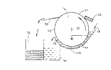
Electrostatic separator apparatus for the separation of particles from a liquid including a drum (10) having a drum surface
(12), means for supplying a particle dispersion comprising particles dispersed in a liquid to the drum surface (12), electrostatic
means for causing at least some of the particles to adhere to the drum surface (12) in a nonimagewise configuration, resilient
blade means (22), downstream of the electrostatic means, for operative engagement with the drum surface (12) for retaining a
layer (24) of particle rich material on the drum surface (12), and layer removal means (30) for layerwise removing substantially all of
said layer (24) from the drum surface (12).


French Abstract

Séparateur électrostatique pour la séparation de particules d'un liquide comprenant un tambour (10) qui a une surface de tambour (12), un moyen de fournir une dispersion de particules constituée de particules dispersées dans un liquide à la surface du tambour (12), un moyen électrostatique pour amener au moins une partie des particules à adhérer à la surface du tambour (12) en une configuration ne formant pas image, une lame élastique (22) en aval du moyen électrostatique pour mise en prise fonctionnelle sur la surface du tambour (12) pour retenir une couche (24) de matériau riche en particules à la surface du tambour (12), et un moyen d'enlèvement de la couche (30) pour enlever substantiellement toute ladite couche (24) de la surface du tambour (12).

Claims

Note: Claims are shown in the official language in which they were submitted.


WE CLAIM:
1. Electrostatic separator apparatus for the separation of particles from a liquid
comprising:
a drum having a drum surface;
means for supplying a particle dispersion comprising particles dispersed in
a liquid to the drum surface;
electrostatic means for causing at least some of the particles to adhere to the
drum surface without forming an image thereon;
resilient blade means, downstream of the electrostatic means, for operative
engagement with the drum surface for retaining a layer of particle rich material on
the drum surface; and
layer removal means for layerwise removing substantially all of said layer
from the drum surface.
2. Apparatus according to claim 1 wherein said blade is maintained at a
potential different from the potential of said drum surface.
3. Apparatus according to claim 1 or claim 2 wherein said particles are
charged and said blade means is maintained at a potential which is operative to
repel said particles toward said drum surface.
4. Apparatus for the separation of particles from a liquid comprising:
a drum having a drum surface;

means for supplying a particle dispersion comprising particles dispersed in
a liquid to the drum surface;
electrostatic means for causing at least some of the particles to adhere to the
drum surface without forming an image thereon;
retaining means downstream of the electrostatic means for operative
engagement with the drum surface for retaining a layer of particle rich material on
the drum surface, said means maintained at a potential different from that of the
drum surface; and
layer removal means for layerwise removing of substantially all of said
layer from the drum surface.
5. Apparatus according to claim 4 wherein said retaining means comprises a
blade.
6. Apparatus according to claim 4 wherein said retaining means comprises a
squeegee roller.
7. Apparatus according to any of claim 4-6, wherein said particles are charged
and said retaining means is operative to repel said particles toward said drum
surface.
8. Apparatus according to any of the preceding claims wherein said means for
supplying comprises a bath through which said drum surface travels.

11
9. Apparatus for separation of toner particles from a carrier liquid comprising
a surface means for repeatedly supplying a layer of material relatively rich in toner
particles and containing liquid carrier liquid to the surface and for subsequently
concentrating said layer and removing therefrom a substantial portion of the carrier
liquid.
10. Apparatus according to claim 9 wherein said toner material is charged and
said concentrating means is maintained at a potential of the same sign as the charge
on the toner particles.
11. Apparatus according to claim 9 or claim 10 wherein said concentrating
means comprises a blade.
12. Apparatus according to claim 10 or claim 11 wherein said concentrating
means comprises a squeegee roller.
13. Apparatus for the separation of particles from a liquid comprising:
a drum having a resilient drum surface;
means for supplying a particle dispersion comprising particles to the drum
surface;
means for causing at least some of the particles to adhere to the drum
surface; and

12
retaining means for operative engagement with the drum surface for
retaining a layer of particle rich material on the drum surface without forming an
image thereon.
14. Apparatus according to any of claims 9-13 and comprising means for
layerwise removal of said layer from the drum surface.
15. Electrostatic separator apparatus for the separation of particles from a liquid
comprising:
a drum having a drum surface;
means for supplying a particle dispersion in a liquid to the drum surface;
electrostatic means for causing at least some of the particles to adhere to the
drum surface;
resilient blade means, downstream of the means for causing, for operative
engagement with the drum surface for retaining a layer of particle rich material on
the drum surface; and
removal means for removing of said layer from the drum surface,
wherein an image is not formed in said layer.
16. Apparatus for the separation of particles from a liquid comprising:
a drum having a drum surface;
means for supplying a particle dispersion in a liquid to the drum surface;
means for causing at least some of the particles to adhere to the drum
surface without forming an image thereon;

13
retaining means downstream of the means for causing for operative
engagement with the drum surface for retaining a layer of particle rich material on
the drum surface, said means maintained at a potential different from that of the
drum surface; and
removal means for removing of said layer from the drum surface,
wherein an image is not formed in said layer.
17. Apparatus according to claim 15 or claim 16 wherein said removal means
comprises means for layerwise removal of said layer from the drum surface.
18. Apparatus according to any of claims 1-17 wherein said means for
supplying supplies said toner to said drum in a non-imagewise configuration.
19. A method for separation of particles from a liquid comprising the steps of:
supplying a particle dispersion comprising particles in a carrier liquid to a
surface;
causing at least some of the particles in said dispersion to adhere to said
surface without forming an image thereon;
contacting said surface with a resilient blade for retaining a layer of particlerich material on said surface; and
layerwise removing of substantially all of said layer from the surface.

14
20. A method for separation of particles from a liquid comprising the steps of:
supplying a layer of material relatively rich in toner and containing carrier
liquid to a surface;
further concentrating said layer and removing therefrom a substantial
portion of the carrier liquid; and
repeating the steps of supplying and further concentrating to increase the
thickness of said layer.
21. A method according to claim 20 and further comprising the step of:
layerwise removal of said layer from the drum surface.
22. A method for the separation of particles from a liquid comprising the steps
of:
supplying a layer of material relatively rich in toner and containing carrier
liquid to a surface;
supplying a particle dispersion in a liquid to the surface;
causing at least some of the particles to adhere to the surface without
forming an image thereon;
causing operative engagement of an electrified member with the surface for
retaining a layer of particle rich material on the surface; and
layerwise removing of substantially all of said layer from the surface.

Description

Note: Descriptions are shown in the official language in which they were submitted.


CA 020~6422 1998-04-23
ELECTROSTATIC SEPARATOR
The present invention relates to separation of charged
particles from a liquid and more particularly to the removal
of charged toner particles from a liquid.
Separation of toner particles from carrier liquid is
important in various applications of electrophotography.
Various types of separation apparatus are known in the
patent literature. For example, there is described in U.S.
Patent 4,737,268 apparatus for electrostatically separating
particles in a liquid stream. The technique of U.S. Patent
4,737,268 is essentially a plating operation and thus
requires periodic deplating in order to operate.
There is described in U.S. Patent 4,504,138 a method
and apparatus for developing electrostatic latent images
wherein a thin highly viscous layer of concentrated toner
particles is defined on a roller, portions of the layer
being transferred to an image bearing surface by
electrostatic means.
U.S. Patent 4,799,452 describes a system for separating
toner particles from carrier liquid in which an electrically
biased electrode repels the solid pigment particles toward a
particle accumulating surface.
It is an object of the present invention to provide
improved apparatus for separating toner particles from a
carrier liquid and for creating a layer of concentrated
toner particles.
There is thus provided in accordance with a preferred
embodiment of the present invention electrostatic separator
apparatus for the separation of particles, preferably toner
particles, from a liquid including a surface, apparatus for
supplying a particle dispersion comprising charged particles
dispersed in a liquid to the surface, electrostatic
apparatus for causing particles to adhere to the surface in
a non-imagewise configuration to form a layer of material
having a proportion of particles which is higher than that
in said dispersion and apparatus for removing substantially

CA 020~6422 1998-04-23
all of the layer from the surface without forming an image in
the layer, characterized in that the electrostatic separator
apparatus includes concentrating apparatus, preferably urged
against the surface, for further increasing the proportion of
particles in the layer, before removing substantially all of
the layer from the surface.
Preferably the concentrating apparatus is maintained at
an electrical potential different from the electrical
potential of the surface, preferably at a potential which is
operative to repel said particles toward said surface,
preferably a potential having the same sign as that of said
particles.
In a preferred embodiment of the invention the
concentrating apparatus includes a blade, in another preferred
embodiment it includes a squeegee roller.
In a preferred embodiment of the invention the apparatus
for supplying includes comprises a bath through which said
surface travels.
In a preferred embodiment of the invention the apparatus
for supplying the electrostatic apparatus and the apparatus
for concentrating are arranged to repeatedly supply additional
toner particles to the surface and increase their proportion
thereon prior to removal of the layer, whereby a thicker layer
of particles is formed on the surface prior to removal of the
thicker layer by the apparatus for removing.
There is further provided in a preferred embodiment of
the invention, a method for separating particles from a liquid
including the steps of supplying a particle dispersion
comprising charge particles in a carrier liquid to a surface,
causing particles in the dispersion to adhere to the surface
in a non-imagewise configuration, using an electric field to
form a layer of material having a proportion of particles
which is higher than that of the dispersion, removing
substantially all of the layer from the surface without
forming an image in said layer, characterized in that the

CA 020~6422 1998-04-23
method includes the step of increasing the proportion of
particles in said layer, prior to the step of removing.
A preferred embodiment of the invention also includes the
step of repeating the steps of supplying, causing and
increasing prior to the step of removing.
Preferably the method includes the step of using and
electrified compactor at the increasing step.
Preferred embodiments of the present invention will now
be described, by way of example only, with reference to the
attached figures wherein:
Fig. 1 is a schematic illustration of apparatus
constructed and operative in accordance with a preferred
embodiment of the present invention; and
Fig. 2 is a schematic illustration of apparatus
constructed and operative in accordance with a preferred
embodiment of the present invention.
Reference in now made to Fig. 1, which illustrates
apparatus constructed and operative in accordance with a
preferred embodiment of the invention including a drum 10,
typically formed of metal and having a preferably cylindrical
drum surface 12, also typically formed of metal. Preferably
drum surface 12 is grounded.
There is provided a liquid toner bath 14, typically
defined by a negatively biased electrode 15, and which defines
an inlet 16 for receipt of liquid toner and an outlet 18,
typically disposed lower than inlet 16, for removal of carrier
liquid which is relatively free of toner particles. Toner
bath 14 is arranged preferably such that approximately one
half of the drum diameter is immersed in the bath at the side
of inlet 16 and less than one half of the drum diameter is
immersed in the bath at the side of outlet 18. The toner
located in bath 14 typically comprises negatively charged
particles. If alternatively it is desired to employ
positively charged toner particles, the electrode 15 is
accordingly positively biased.

CA 020~6422 1998-04-23
--4--
In the illustrated embodiment, the drum rotates in the
direction of arrow 20 from the side adjacent outlet 18 through
the bath 14 to the side ad~acent inlet 16. Downstream of bath
14 there is provided a first blade 22, typically arranged at
the upper, upward rotating quadrant of the drum surface 12,
for operatively engaging the drum surface 12. According to a
preferred embodiment of the invention, the first blade is
operative to define on the drum surface a layer 24 of
relatively viscous concentrated liquid toner.
According to a preferred embodiment of the present
invention, the first blade is typically formed of resilient
polyurethane with a Shore A hardness of typically 20-60 and
thickness 2 mm and is arranged to apply a total pressure of
about 100 grams along a length of about 20 cm.
Use of a resilient blade provides a generally uniform
pressure to the layer of toner material notwithstanding
variations in the relative positioning of the drum surface
thereto.
According to a possible alternative embodiment of the
invention the drum surface 12 is formed of relatively
resilient material and the first blade 22 may be formed of
relatively less resilient material.
According to a preferred embodiment of the invention, the
first blade may be maintained at a potential which is the same
in sign as that of the charge on the toner particles, to
compact the image and aid in liquid removal. For this
embodiment the blade may be made of conductive resilient
polymeric materials as described in either or both of U.S.
Patents 3,959,574 and 3,863,603 which are incorporated herein
by reference. In order to avoid the possibility of short
circuits or arcing, as for example when there are no toner
particles on the drum, current limitation may be added to the
potential power supply.
In accordance with an embodiment of the invention, the
apparatus of the present invention may also include scraper

~ CA 020~6422 l998-04-23
blade apparatus 30, which typically operatively engages the
drum surface 12 at the upper, downward rotating quadrant of
the drum surface. Scraper blade apparatus 30 iS operative to
remove layer 24 and to direct the relatively viscous
concentrated liquid toner of which layer 24 iS composed to a
concentrated dispersion tank 32. A tank 34 may be also
provided for receipt of relatively clear carrier liquid from
outlet 18. It is appreciated that scraper blade apparatus 30
may alternatively be eliminated.
According to a preferred embodiment of the invention an
inlet toner particle concentration of about 1.5% may be used
with a bath electrode potential of approximately -800 to -1000
volts when the electrode is separated from the drum 10 by a
distance of about 500 micrometers. For a typical drum
diameter of 120 mm, a drum surface linear velocity of about 10
cm/sec may be employed. It is appreciated that when the
scraper blade apparatus 30 is not used or is disengaged, the
drum and the layer built up thereon may be rotated multiple
times through the bath 14 and past the first blade to provide
enhanced layer uniformity, thickness and concentration. Three
to four such rotations are preferred and provide a layer of
typical thickness of about 5 micrometers. Should it be
desired to remove the built up layer, the scraper blade
apparatus 30 may be re-engaged.
Reference is now made to Fig. 2, which illustrates
apparatus which is substantially similar to the apparatus of
Fig. 1, with the exception that the first blade 22 iS replaced
by a charged squeegee roller 40. Squeegee roller 40 is
typically formed of resilient polymeric material such as that
described in either or both U.S. Patent 3,959,574 and
3,863,603, having a hardness of typically 20 to 60 Shore A and
applies a pressure of to the layer 24 sufficient to form a
nip, typically 0. 5 to 1 cm. Where negatively charged toner
particles are employed it is maintained at a typical voltage
of -750 volts. In order to avoid the possibility of short

CA 020~6422 1998-04-23
circuits or arcing, as for example when there are no toner
particles on the drum, current limitation may be added to the
power supply.
The present invention is especially useful when practiced
with liquid toner materials of the type disclosed in U.S.
Patent 4,794,651 which is incorporated herein by reference.
It is also useful when practiced on a variety of other liquid
toner types.
It will be appreciated by persons skilled in the art that
the present invention is not limited by what has been
particularly shown and described hereinabove. Rather the
scope of the invention is defined only by the following
claims:

Representative Drawing
A single figure which represents the drawing illustrating the invention.
Administrative Status

2024-08-01:As part of the Next Generation Patents (NGP) transition, the Canadian Patents Database (CPD) now contains a more detailed Event History, which replicates the Event Log of our new back-office solution.

Please note that "Inactive:" events refers to events no longer in use in our new back-office solution.

For a clearer understanding of the status of the application/patent presented on this page, the site Disclaimer , as well as the definitions for Patent , Event History , Maintenance Fee  and Payment History  should be consulted.

Event History

Description Date
Time Limit for Reversal Expired 2009-03-05
Letter Sent 2008-03-05
Letter Sent 2003-08-20
Grant by Issuance 1998-08-25
Inactive: Received pages at allowance 1998-04-23
Inactive: Final fee received 1998-04-23
Pre-grant 1998-04-23
Notice of Allowance is Issued 1997-10-23
Letter Sent 1997-10-23
Inactive: Status info is complete as of Log entry date 1997-10-10
Inactive: Application prosecuted on TS as of Log entry date 1997-10-10
Inactive: IPC removed 1997-08-15
Inactive: IPC assigned 1997-08-15
Inactive: First IPC assigned 1997-08-15
Inactive: IPC removed 1997-08-15
Inactive: IPC assigned 1997-08-15
Inactive: IPC removed 1997-08-15
Inactive: IPC assigned 1997-08-15
Inactive: Approved for allowance (AFA) 1997-08-12
Inactive: Delete abandonment 1997-08-08
Inactive: Abandon-RFE+Late fee unpaid-Correspondence sent 1997-03-05
Request for Examination Requirements Determined Compliant 1997-02-18
All Requirements for Examination Determined Compliant 1997-02-18
Application Published (Open to Public Inspection) 1990-09-09

Abandonment History

There is no abandonment history.

Maintenance Fee

The last payment was received on 1998-03-05

Note : If the full payment has not been received on or before the date indicated, a further fee may be required which may be one of the following

  • the reinstatement fee;
  • the late payment fee; or
  • additional fee to reverse deemed expiry.

Patent fees are adjusted on the 1st of January every year. The amounts above are the current amounts if received by December 31 of the current year.
Please refer to the CIPO Patent Fees web page to see all current fee amounts.

Owners on Record

Note: Records showing the ownership history in alphabetical order.

Current Owners on Record
HEWLETT-PACKARD INDIGO B.V.
Past Owners on Record
BENZION LANDA
JAKOB KARIN
PAUL FENSTER
SHABTAI EZUZ
Past Owners that do not appear in the "Owners on Record" listing will appear in other documentation within the application.
Documents

To view selected files, please enter reCAPTCHA code :


To view images, click a link in the Document Description column. To download the documents, select one or more checkboxes in the first column and then click the "Download Selected in PDF format (Zip Archive)" or the "Download Selected as Single PDF" button.

List of published and non-published patent-specific documents on the CPD .

If you have any difficulty accessing content, you can call the Client Service Centre at 1-866-997-1936 or send them an e-mail at CIPO Client Service Centre.


Document
Description 
Date
(yyyy-mm-dd) 
Number of pages   Size of Image (KB) 
Claims 1994-03-11 5 191
Abstract 1994-03-11 1 59
Drawings 1994-03-11 1 20
Claims 1997-06-10 6 156
Description 1997-06-10 6 285
Description 1998-04-22 6 256
Representative drawing 1998-08-12 1 6
Commissioner's Notice - Application Found Allowable 1997-10-22 1 165
Maintenance Fee Notice 2008-04-15 1 172
Correspondence 1997-10-22 1 99
Correspondence 1998-04-22 1 33
Fees 1998-03-04 1 43
Correspondence 1998-04-22 7 280
Fees 1997-02-17 1 49
Fees 1995-03-02 1 43
Fees 1994-03-03 1 40
Fees 1996-03-03 1 48
Fees 1993-03-03 1 36
Fees 1992-03-03 1 34
International preliminary examination report 1991-09-08 28 1,039
Prosecution correspondence 1997-02-17 1 35
Prosecution correspondence 1997-04-16 2 37
Courtesy - Office Letter 1992-02-11 1 22
Courtesy - Office Letter 1992-02-19 1 16