Language selection

Search

Patent 2056763 Summary

Third-party information liability

Some of the information on this Web page has been provided by external sources. The Government of Canada is not responsible for the accuracy, reliability or currency of the information supplied by external sources. Users wishing to rely upon this information should consult directly with the source of the information. Content provided by external sources is not subject to official languages, privacy and accessibility requirements.

Claims and Abstract availability

Any discrepancies in the text and image of the Claims and Abstract are due to differing posting times. Text of the Claims and Abstract are posted:

  • At the time the application is open to public inspection;
  • At the time of issue of the patent (grant).
(12) Patent Application: (11) CA 2056763
(54) English Title: TUNNEL BORING MACHINE
(54) French Title: MACHINE DE CREUSAGE DE TUNNEL
Status: Dead
Bibliographic Data
(51) International Patent Classification (IPC):
  • E21D 9/10 (2006.01)
(72) Inventors :
  • HARTWIG, SVERKER (Sweden)
(73) Owners :
  • ATLAS COPCO CONSTRUCTION AND MINING TECHNIQUE AB (Sweden)
(71) Applicants :
(74) Agent: FETHERSTONHAUGH & CO.
(74) Associate agent:
(45) Issued:
(22) Filed Date: 1991-12-02
(41) Open to Public Inspection: 1992-06-14
Availability of licence: N/A
(25) Language of filing: English

Patent Cooperation Treaty (PCT): No

(30) Application Priority Data:
Application No. Country/Territory Date
9003979-3 Sweden 1990-12-13

Abstracts

English Abstract


Abstract:

Tunnel boring machine whose driving shaft (4) adjacent to the boring
head (6) is journalled in a bearing (12) which is intended to take up
only radial forces. Shaft (4) is at its other end journalled in
bearings (13,14) which take up both radial and axial forces.


90011.ut1


Claims

Note: Claims are shown in the official language in which they were submitted.


Claim:

1. Tunnel boring machine comprising a machine housing (1) which
is clampable in a tunnel (2), a shell (3) movable to-and-fro in the
machine housing, a shaft (4) rotatably arranged in said shell, whereby
said shaft at one (5) of its ends carries a boring head (6), said
shell at its from the boring head directed end (7) being provided with
a gear box (8) on which a number of driving motors (9) are arranged,
said shaft being rotatably journalled relative to said shell and a
number of pressure fluid cylinders (10) being arranged between said
machine housing and said shaft in order to press said boring head
against a tunnel front (11), c h a r a c t e r i z e d in that said
shaft (4) adjacent to the boring head (6) is journalled in said shell
(3) by means of a bearing (12) which is intended to only take up
radial forces and at said gear box (8) is journalled by means of
bearings (13,14) which take up both radial and axial forces.


90011.ut1

Description

Note: Descriptions are shown in the official language in which they were submitted.


Z~S763

Tunnel borinq machine

The present invention relates to a tunnel boring machine, i.e. a
machine by means of which a tunnel is bored to full area without using
explosives.

It has long been a desire to be able to construct machines of the
above mentioned kind for different tunnel diameters and thereby use
module designs which are the same for the different tunnel diameters.
Machines designed according to these ideas would be substantially
cheaper because fewer parts need be specially designed for individual
machines. Machines which comply with the above mentioned desire must
have a driving shaft for the boring head which can stand the torque
which the biggest machine recluires. This gives a large diameter. At
the same time the bearing adjacent to the boring head must admit
passage, for instance for exchange of boring tools, in the smallest
contemplated tunnel dià~eter.

The presen~ invention, which is defined in the subsequent claim, aims
at achieving a tunnel boring machine which admits the mounting of
boring heads with comparatively different diameters on the same
driving shaft. This is achieved by, contrary to prior art, journalling
the driving shaft for the boring head in a bearing adjacent to the
boring head which is only intended for radial forces. Through this a
substantial diameter reduction of the design is obtained directly
behind the boring head. The axial forces are transferred from the
machine housing via bearings at the rear end of the machine to the
rotational shaft for the boring head and from there to the boring
head.

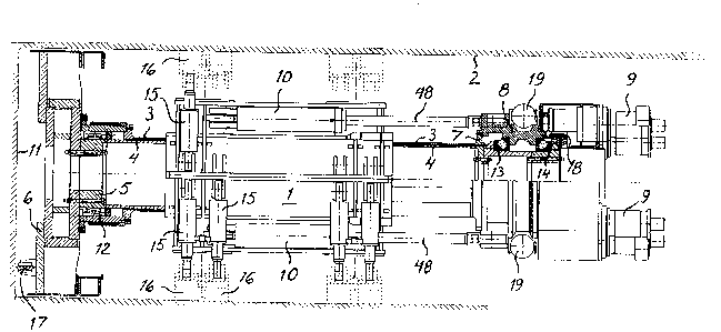
An embodiment of the invention is described below with reference to
the accompnying drawing which schematically shows a section through a
tunnel boring machine according to the invention.

The tunnel boring machine shown in the drawing comprises a machine
housing 1 which by means of hydraulic cylinders 15 and clamping shoes
16 is clampable in a tunnel 2. A shell 3 is movable to-and-fro in the
machine housing and prevented from rotation about its longitudinal
axis by the machine housing. In shell 3 a shaft ~ is rotatably

90011.utl

i763
journalled. Shaft 4 carries at its front end 5 a boring head 6 which
is provided with a number of cutters 7, one shown, for the working of
a tunnel front 11. Shaft 4 is at its front end journalled, by means of
a bearing 12, in the shown example a spherical roller bearing, which
is only intended for the taking up of radial forces, in shell 3. Shell
3 is supported adjacent to bearing 12 by a not shown support foot. The
drawing shows the tunnel boring machine from above making the support
foot obscured. Shell 3 is at its end 7 far from the boring head
provided with a gear box 8 on which a number of driving motors 9 are
arranged. Shaft 4 is by means of bearings 13,14, in the shown example
conical roller bearings,journalled in the gear box 8. These bearings
are intended for the taking up of both radial and axial forces. The
outgoing shafts of the driving motors transfer torque via the gear
wheel 18 to shaft 4. In order to press boring head 6 against the
tunnel front 11 a number of pressure fluid cylinders 10 provided with
piston rods 48 are arranged between machine housing 1 and shaft 4 via
gear box 8. Gear box 8 is provided with two hydraulic cylinders 19
which carry not shown support feet.

In order to adjust the machine to different tunnel diameters boring
head 6 can be exchanged, driving motors 9 can be exchanged or the
number of driving motors can be changed. Furthermore, the number of
clamping shoes 16 can be adjusted to the transferred torque.


90011.utl

Representative Drawing
A single figure which represents the drawing illustrating the invention.
Administrative Status

For a clearer understanding of the status of the application/patent presented on this page, the site Disclaimer , as well as the definitions for Patent , Administrative Status , Maintenance Fee  and Payment History  should be consulted.

Administrative Status

Title Date
Forecasted Issue Date Unavailable
(22) Filed 1991-12-02
(41) Open to Public Inspection 1992-06-14
Dead Application 1999-12-02

Abandonment History

Abandonment Date Reason Reinstatement Date
1998-12-02 FAILURE TO PAY APPLICATION MAINTENANCE FEE
1998-12-02 FAILURE TO REQUEST EXAMINATION

Payment History

Fee Type Anniversary Year Due Date Amount Paid Paid Date
Application Fee $0.00 1991-12-02
Registration of a document - section 124 $0.00 1992-06-23
Maintenance Fee - Application - New Act 2 1993-12-02 $100.00 1993-11-26
Maintenance Fee - Application - New Act 3 1994-12-02 $100.00 1994-11-25
Maintenance Fee - Application - New Act 4 1995-12-04 $100.00 1995-11-24
Maintenance Fee - Application - New Act 5 1996-12-02 $150.00 1996-11-22
Maintenance Fee - Application - New Act 6 1997-12-02 $150.00 1997-11-26
Owners on Record

Note: Records showing the ownership history in alphabetical order.

Current Owners on Record
ATLAS COPCO CONSTRUCTION AND MINING TECHNIQUE AB
Past Owners on Record
HARTWIG, SVERKER
Past Owners that do not appear in the "Owners on Record" listing will appear in other documentation within the application.
Documents

To view selected files, please enter reCAPTCHA code :


To view images, click a link in the Document Description column. To download the documents, select one or more checkboxes in the first column and then click the "Download Selected in PDF format (Zip Archive)" or the "Download Selected as Single PDF" button.

List of published and non-published patent-specific documents on the CPD .

If you have any difficulty accessing content, you can call the Client Service Centre at 1-866-997-1936 or send them an e-mail at CIPO Client Service Centre.


Document
Description 
Date
(yyyy-mm-dd) 
Number of pages   Size of Image (KB) 
Cover Page 1992-06-14 1 13
Abstract 1992-06-14 1 7
Claims 1992-06-14 1 23
Drawings 1992-06-14 1 42
Description 1992-06-14 2 84
Representative Drawing 1999-07-06 1 39
Fees 1996-11-22 1 79
Fees 1995-11-24 1 77
Fees 1994-11-25 2 124
Fees 1993-11-26 1 57