Language selection

Search

Patent 2056778 Summary

Third-party information liability

Some of the information on this Web page has been provided by external sources. The Government of Canada is not responsible for the accuracy, reliability or currency of the information supplied by external sources. Users wishing to rely upon this information should consult directly with the source of the information. Content provided by external sources is not subject to official languages, privacy and accessibility requirements.

Claims and Abstract availability

Any discrepancies in the text and image of the Claims and Abstract are due to differing posting times. Text of the Claims and Abstract are posted:

  • At the time the application is open to public inspection;
  • At the time of issue of the patent (grant).
(12) Patent: (11) CA 2056778
(54) English Title: CONTROL OF FURNACE CLEANING FOR REFLECTIVE ASH USING INFRARED IMAGING
(54) French Title: CONTROLEUR DE PROPRETE DE CHAUDIERE POUR SUIE A REFLECTIVITE ELEVEE
Status: Expired and beyond the Period of Reversal
Bibliographic Data
(51) International Patent Classification (IPC):
  • G01N 21/84 (2006.01)
  • F23J 3/00 (2006.01)
(72) Inventors :
  • CARTER, HUDSON R. (United States of America)
(73) Owners :
  • DIAMOND POWER INTERNATIONAL, INC.
(71) Applicants :
(74) Agent: SMART & BIGGAR LP
(74) Associate agent:
(45) Issued: 2000-02-08
(22) Filed Date: 1991-12-02
(41) Open to Public Inspection: 1992-06-04
Examination requested: 1996-09-13
Availability of licence: N/A
Dedicated to the Public: N/A
(25) Language of filing: English

Patent Cooperation Treaty (PCT): No

(30) Application Priority Data:
Application No. Country/Territory Date
621,417 (United States of America) 1990-12-03

Abstracts

English Abstract


A method and apparatus for monitoring reflective ash
deposited on a furnace wall to be cleaned
comprises an infrared video camera or other
mechanism for taking an infrared image of the fur-nace
wall. The image must include an area to be cleaned by
the waterblowing as well as a surrounding uncleaned
area. Photo detectors or other mechanisms are utilized
to measure the image intensity at locations on the
cleaned and uncleaned areas with a ratio between the
intensities being taken. The cleaned area has low
reflectivity and is dark compared to the uncleaned area
which is white and has high image intensity. The image
intensity ratio between the cleaned area and the
uncleaned area thus rises from a low level immediately
after waterblowing to a high level which approaches
unity as the initially cleaned area becomes as unclean
as the uncleaned area. This can be used as an
indication when waterblowing must be manually initiated,
or the ratio signal can be used directly to operate an
automatic system to initiate waterblowing.


Claims

Note: Claims are shown in the official language in which they were submitted.

8
CLAIMS:
1. A method for controlling periodic furnace wall cleaning
by distinguishing between a clean condition for a furnace wall
from an unclean condition for high reflectivity ash deposited
on the furnace wall which has at least one area to be cleaned
and a remaining uncleaned reference area, comprising the steps
of:
taking a near infrared image of the furnace wall
including the area to be cleaned and the uncleaned reference
area;
measuring image intensity at a location on the area to
be cleaned and establishing a signal indicative thereof;
measuring image intensity at a location on the uncleaned
reference area and establishing a signal indicative thereof;
supplying the image intensity signals to a signal
processor for determining a ratio between the image
intensities of the area to be cleaned and reference area;
comparing the ratio of the image intensities with a
selected value for distinguishing an unclean condition for the
furnace wall from a clean condition; and
initiating furnace wall cleaning when the ratio reaches
the selected value indicating the unclean condition of the
furnace wall.
2. A method according to claim 1 including utilizing an
infrared video camera to take the image and to measure the
image intensity at the locations of the cleaned and reference
areas.
3. A method according to claim 1 including displaying the
ratio as it changes as a function to time to indicate the
increase of reflectivity in the cleaned area corresponding to
an ever increasing deposit of ash.
4. A method according to claim 1 including measuring a
selected peak of the ratio and utilizing the peak to control
the initiation of a waterblowing operation to clean the

9
cleaned area.
5. A method according to claim 1, wherein the furnace wall
cleaning includes steam blowing.
6. A method according to claim 1, wherein the furnace wall
cleaning includes air blowing.
7. A method according to claim 1, wherein the furnace wall
cleaning includes water blowing.
8. An apparatus for controlling periodic furnace cleaning
by distinguishing a clean condition for a furnace wall from
an unclean condition by monitoring high reflectivity ash
deposited on the furnace wall having at least one area to be
cleaned and a remaining uncleaned reference area, comprising:
means for generating a near infrared image of the wall
including the area to be cleaned and the uncleaned reference
area;
means for measuring the image intensity at a location in
the area to be cleaned and establishing a signal indicative
thereof;
means for measuring the image intensity at a location in
the uncleaned reference area and establishing a signal
indicative thereof; and
a signal processor receiving the image intensity signals
to calculate a ratio between the image intensities which
represents a measurement of the furnace wall ash deposit on
the area of the furnace wall to be cleaned, said signal
processor comparing the ratio with a selected value for
distinguishing an unclean condition from a clean condition of
the furnace wall, said signal processor providing an output
signal indicative of the unclean condition on the furnace wall
when the ratio reaches the selected value.
9. An apparatus according to claim 8, wherein said means for
providing the near infrared image comprises an infrared camera
for imaging the furnace wall.

10
10. An apparatus according to claim 8, wherein the means for
measuring the image intensity comprise photo detectors
positioned over the respective locations on the infrared
image.
11. An apparatus according to claim 8 including automatic
means for connection to a cleaning mechanism, said automatic
means being connected to the signal processor and being
responsive to said output signal for being activated when the
ratio reaches the selected value.
12. An apparatus according to claim 11, wherein the cleaning
mechanism comprises water blowing equipment.
13. An apparatus according to claim 11, wherein the cleaning
mechanism comprises steam blowing equipment.
14. An apparatus according to claim 11, wherein the cleaning
mechanism comprises air blowing equipment.
15. An apparatus according to claim 8, wherein said signal
processor displays the ratio on a display as it changes as a
function of time to indicate the increase of reflectivity in
the cleaned area corresponding to an ever increasing deposit
of ash.

Description

Note: Descriptions are shown in the official language in which they were submitted.


205G7'~~
CASE' 5114
-1-
FURNACE CLEANLINESS MONITOR, FOR HIGH REFLECTI~IITY ASIi
The present invention relates in general to
monitors for use in furnaces and other high temperature,
dirty environments, and in particular to a new and
useful monitor which is capable of determining the
cleanliness of a furnace wall that receives deposits of
highly reflective ash.
Western fuels, such as Powder River Basin (PRB)
coals, are low in sulfur; however, they are high in
calcium and silicon. This composition results in a
thin, white tenacious ash on the furnace walls . This ash
(called slag) is,not easily removed using conventional
air or steam cleaning devices.
. A number of utilities are currently burning PRB
coal and more are expected to switch to Pltl~ coal wiLl~
the passage of the Clean Air Act. The PRB coal

f
2
depo:~ited ash is highly reflective. The ash reduces the
heat absorption of the furnace causing high temperatures
in tire convection passes of the boiler.
hlaterblowing has been shown to be effective in
removing the ash and restoring furnace heat transfer
effectiveness. More utilities are expected to employ
waterblowing when PRB coal is used.
The PRB ash deposit is thin and tight. This is
in stark contrast to the heavy deposits visually appa
rent in furnaces burning other coals. Therefore, the
decision to clean the furnace cannot be made based on a
visual inspection and overcleaning (with water) is not
desired because of thermal shock consideration.
Since there is a thermal shock consideration in
using water, it is desirable to only clean the wall when
cleaning is necessary. All plants currently clean on a
time sequence. Most plants use a cleaning period of
about four hours. Video recording taken at one plant
reveals that for the hot wall (this was a CE tangential
fired boiler) four hours was an appropriate time period.
However, on the cold wall a much longer period than four
hours should be used. Based on the video recording even
after ten haurs the cold wall was still relatively
clean.
A need thus exists for apparatus and techniques
which are capable of accurately distinguishing between
a clean condition for the furnace wall which does not
require immediate waterblowing, and an unclean condition
which does require waterblowing.
I Setnnrl ~nv..............._...._

CA 02056778 1999-06-23
3
The present invention is based on the discovery that an
infrared picture taken of a furnace wall, shows that clean
surfaces appear nearly black while slag covered surfaces are
white. In the near-infrared region (approximately 1.5 to 2.1
microns) the image viewed is a temperature image. Therefore
the black or dark area is cooler than the white area. The
clean surfaces are cooler than the dirty surfaces because the
clean surfaces are closer to the inside diameter of the
coolant flow in the furnace wall. Therefore, the cooler
surfaces are the cleaner, and thus darker, surfaces.
To apply this discovery, a measurement is taken of the
intensity ratio between a known cleaned area of the furnace
wall as viewed on a video image screen, and an area which has
not been cleaned. As this ratio approaches 1 (indicating that
the cleaned area is no longer clean) waterblowing,
steamblowing or airblowing, or combinations thereof are
cleaning equipment of known design. Since the equipment
produces a clean area of known extent, the distinction between
the intensity of the cleaned area and the intensity of an
uncleaned area (which is never reached by the water lance) is
readily made.
An infrared video image can be produced using the known
infrared monitoring equipment disclosed in U.S. Patent
4,539,588. This equipment or conventional photodetection
equipment can be used for measuring the intensities of the
clean area and reference area and conventional calculating

20~6i~8
4
equipment utilized to establish the ratio.
Accordingly, an object of the present invention
is to provide a method of monitoring for high
reflectivity ash deposited on a furnace wall wl~icli has
at least one area to be cleaned by waterblowing and a
remaining uncleaned reference area, comprising: taking
a near infrared image of the wall including the cleaned
area and the uncleaned reference area; measuring image
intensity at a location on the cleaned area; measuring
image intensity at a location on the reference area; and
determining the ratio between the image intensities of
the cleaned and reference areas as a measurement of the
amount of high reflectivity ash deposited on the furnace
wall.
A further object of the present invention is to
provide an apparatus for monitoring the furnace wall.
A still further object of the present invention
is to provide a method and apparatus for monitoring the
furnace wall which is simple in design, rugged in
construction and economical to manufacture.
BRIEF DESCRIPTION OF THE DRAWING
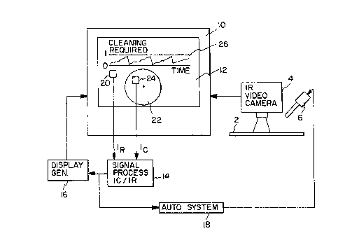
The only figure in the drawing is a schematic
representation of the apparatus of the present
invention.
DESCRIPTION OF THE PREFERRED EMBODIMENT'
Referring to the drawing in particular, the
.,
i s~~~~H .""..,..,.............._

.. ~0567'~8
invention embodied therein comprises an infrared camera
4 for viewing a near infrared image of a furnace wall 2
which is to be periodically cleaned by a water lance 6.
The video camera is connected to a monitor lU wtrictr lras
S a screen 12 which, at its lower half, displays the
furnace wall which includes an area 22 which is expected
to be cleaned by the water lance 6, and a remaining
reference area around the cleaned area 22, which is not
expected to be cleaned by the waterblowing operation.
A first photo detector 20 is positioned at a location in
the uncleaned reference area while a second photo
detector 24 is positioned at a location. in the clean
area 2Z. ~ It is expected that immediately after the
cleaning operation, the cleaned area 22 will be dark or
black while the uncleaned surrounding area will be white
or highly reflective. The intensities of the two areas
are supplied as signals to a signal processor 14 which
takes the ratio between the clean area intensity I~ and
the reference area intensity In to drive a display
generator 16 which produces a display 26 at the upper
half'of screen 12. Display 26 is in the form of a graph
which plots the ratio of I~/In over time. 'fhe gradually
increasing slope of the repeating pattern represents the
slow deposition of reflective ash on the furnace wall 2.
Since the intensity of area 22 is initially very low
while the intensity of the dirty area at location 20 is
substantially constant and relatively high, the value on
display 26 increases from near 0 to near 1 as ash is
deposited. When the cleaned area is nearly as
' reflective as the uncleaned area, ttris indicates a point
when waterblowing must be initiated. At that point, a
..,.".,. .,.... _......

r ,,~ .,___ ._.
s
6
rapid cleaning takes place which results in a rapid
decrease in the ratio as shown in display 26.
The signal from signal processor 14 may also be
used to drive an automatic WL activation system 1$ which
activates the water lance 16 when~the selected eak
p
values for the ratio (near unity) is reached on a
periodic basis,
Although a single clean area 22 is illustrated,
it is understood that several water lances rnay be used
in a pattern which is preferably non-overlapping, The
non-overlapping nature of the generally circular
patterns is selected since the overlapping areas (which
are cleaned by two water lances) would be subjected to
excessive thermal shock.
The use of the invention also avoids excessive
and unnecessary cleaning which not only saves energy and
wear on the WL system, but also reduces thermal -shock to
the furnace walls.
Although a real-time video monitor 10 is
illustrated, snap shots or other static images may be
...
generated using the video camera 4. Alternatively, an
array of near infrared sensors may be utilized to
generate the image or any other infrared image system
may be utilized.
Photo detectors 20 and 24 may be replaced by
any other mechanism which is capable of detecting
intensity in the image.
~'he--pr-eser~.t~nvention-is-particularly suited
f°~~'°~e~s-ha-v.i~zg_an~utput-of-appr°ximately 400 MW or
1 es s ;
Actual tests that have been conducted on at

s
.. . ~ ~ ~ 2056~"~~
lEaast one power generating station have verified the
usefulness and applicability of the present invention to
monitor and control waterblowing operations,
While a specific embodiment of tire invention
has been shown and described in detail to illustrate the
application of the principles of the invention, it will
be understood that the invention may be ernbodied
otherwise without departing from such principles.
I Snr:nnn ~n..............,..__..__

Representative Drawing
A single figure which represents the drawing illustrating the invention.
Administrative Status

2024-08-01:As part of the Next Generation Patents (NGP) transition, the Canadian Patents Database (CPD) now contains a more detailed Event History, which replicates the Event Log of our new back-office solution.

Please note that "Inactive:" events refers to events no longer in use in our new back-office solution.

For a clearer understanding of the status of the application/patent presented on this page, the site Disclaimer , as well as the definitions for Patent , Event History , Maintenance Fee  and Payment History  should be consulted.

Event History

Description Date
Inactive: IPC from MCD 2006-03-11
Time Limit for Reversal Expired 2003-12-02
Letter Sent 2002-12-02
Grant by Issuance 2000-02-08
Inactive: Cover page published 2000-02-07
Inactive: Final fee received 1999-10-26
Pre-grant 1999-10-26
Notice of Allowance is Issued 1999-08-20
Letter Sent 1999-08-20
Inactive: Approved for allowance (AFA) 1999-08-05
Inactive: Correspondence - Formalities 1999-06-23
Amendment Received - Voluntary Amendment 1999-06-23
Inactive: S.30(2) Rules - Examiner requisition 1999-02-23
Inactive: Multiple transfers 1998-09-16
Inactive: Status info is complete as of Log entry date 1998-01-29
Inactive: Application prosecuted on TS as of Log entry date 1998-01-29
All Requirements for Examination Determined Compliant 1996-09-13
Request for Examination Requirements Determined Compliant 1996-09-13
Application Published (Open to Public Inspection) 1992-06-04

Abandonment History

There is no abandonment history.

Maintenance Fee

The last payment was received on 

Note : If the full payment has not been received on or before the date indicated, a further fee may be required which may be one of the following

  • the reinstatement fee;
  • the late payment fee; or
  • additional fee to reverse deemed expiry.

Please refer to the CIPO Patent Fees web page to see all current fee amounts.

Owners on Record

Note: Records showing the ownership history in alphabetical order.

Current Owners on Record
DIAMOND POWER INTERNATIONAL, INC.
Past Owners on Record
HUDSON R. CARTER
THE BABCOCK & WILCOX COMPANY
Past Owners that do not appear in the "Owners on Record" listing will appear in other documentation within the application.
Documents

To view selected files, please enter reCAPTCHA code :


To view images, click a link in the Document Description column. To download the documents, select one or more checkboxes in the first column and then click the "Download Selected in PDF format (Zip Archive)" or the "Download Selected as Single PDF" button.

List of published and non-published patent-specific documents on the CPD .

If you have any difficulty accessing content, you can call the Client Service Centre at 1-866-997-1936 or send them an e-mail at CIPO Client Service Centre.


Document
Description 
Date
(yyyy-mm-dd) 
Number of pages   Size of Image (KB) 
Representative drawing 1999-07-21 1 10
Representative drawing 2000-01-21 1 9
Claims 1994-01-29 2 58
Abstract 1994-01-29 1 26
Cover Page 1994-01-29 1 12
Description 1994-01-29 7 188
Drawings 1994-01-29 1 13
Description 1999-06-23 7 200
Claims 1999-06-23 3 122
Cover Page 2000-01-21 1 43
Commissioner's Notice - Application Found Allowable 1999-08-20 1 163
Maintenance Fee Notice 2002-12-30 1 173
Correspondence 1999-06-23 3 124
Correspondence 1999-10-26 1 35
Fees 1998-11-23 1 31
Fees 1997-11-19 1 31
Fees 1999-11-22 1 27
Fees 1996-11-25 1 29
Fees 1995-11-14 1 34
Fees 1994-11-23 1 37
Fees 1993-11-15 1 31