Note: Descriptions are shown in the official language in which they were submitted.
-
~7~
METHOD TO EVALUATE THE PITCH AND VOICING OF THE SPEECH
SIGNAL IN VOCODERS WITH VERY SLOW BIT RATES
BACKGROUND OF THE INVENTION
The present invention relates to a method for
evaluating the pitch and voicing of the speech signal
in vocoders with very low bit rates.
In known vocoders with low bit rates, the speech
signal is cut up into 20 ms and 30 ms frames so that
the periodicity or pitch of the speed signal can be
determined within these frames. However, during the
transitions, this period is not stable and errors occur
in the estimation of the pitch and, consequently, in
the estimation of the voicing in these parts. Besides,
if the speech signal is highly noise-affected by the
ambient noise, the evaluation of the pitch is then
highly disturbed or even erroneous.
SUMMARY OF THE INVENTION
The aim of the invention is to overcome the
above-mentioned drawhacks.
; 20 To this effect,~ an object of the invention is a
method to evaluate the pltch and voicing of the~ speech
s1gnal in vocoders with very low bit rates, wherein
there 15 ~carrled~ out a first processing operation
consisting of:
- the cutting up, after sampling, of the signal into
:
~ frames of a determined duration,
,
2 2~71 ~
- the carrying out a first self-adaptive filtering of
the sampled signal (Sn) obtained in each frame to limit
the influence of the first formant,
- the carrying out a second f.iltering to keep only a
minimum of harmonics of the fundamental frequency,
and the comparing of the signal obtained with two
adaptive thresholds SfMin(n) and SfMax(n), respectively
positive and negative and changing as a function of
time according to a predetermined relationship so as to
choose only the signal portions that are respectively
above or below the two thresholds;
and wherein there is carried out a second processing
: operatlon on the signal Scc(n) obtained at the end of
the first processing operation, said second processing
~ 15 operation consisting of:
: : - the computation, on a predetermined number of
.
fundamental frequencies or pitches M possible, of the
self-correlation of the signal obtained at the end of
the first processing operation from a ~ determined
20~ sampling~ insta~nt No and
: ~ - the choosing, as candidate pitch M or fundamental
requency values, those that are equal in number to a
:
predetermined number n corresponding to maxima of
~ : self-correlation and
: ~
- the :entering: of the corresponding values of the
self-correlation in a table of scores updated at each
~ : new self-correlation so as to choose, as a pitch value,
: cnly the value tha~ corresponds to a maximum score.
~' - - .
~ ,- ~, .. . .
,,
~ Q ~
BRIEF DESCRIPTION OF THE DRAWINGS
Other features and advantages of the invention
shall appear here below from the following description,
made with reference to the appended drawings, of which:
- Figure 1 is a flow chart representing an
operation for the pre-processing of the speech signal
implemented by the invention;
- Figure 2 shows examples of the development of
the filtered signal and of the final signal obtained at
the end of the preprocessing line of figure 1;
- Figure 3 is a flow chart for the computation of
K candidate values for the determination of the pitch
according to the invention;
- Figure 4 is a graph used to illustrate a mode of
determining the ~itch from a table of coefficients
representing different possible pitch values;
- Figure 5 is a graph illustrating the working of
.
a voicing indicator.
DESCRIPTION OF THE INVENTION
` The prlnclple of the lnventlon consists in maklng,
;; in~a given~ f~ame,~several estimates of the pitch at
regular lntervals and~ in paylng speclal attention to
:
the successive estimates that have neighboring values,
a quallty factor~being given to each estimate. The
guality factor has a maximum value when the signal is
:
perfectly periodic and a lower value when its
periodicity is less pronounced. Since the voicing is
directly related to the self-correlation of the speech
, -
2 ~
signal for a delay equal to the value of the pitch
chosen, the self-correlation is the maximum for a
voiced sound while it is low for a unvoiced sound. The
indication of the voicing is obtained by comparing the
self-correlation with thresholds after temporal
smoothing and hysteresis operations have been performed
in order to prevent erroneous transitions from the
voiced state to the unvoiced state and vice versa.
The method used for the determination of the
pitches comprises two main processing steps, a
pre-processing step represented by the flow chart of
figure 1 and a self-correlation computation step.
These two steps can easily be programmed on any known
signal processor.
The pre-processing step can be divided in the
manner shown in figure 1 into a self-adaptlve filtering
step 1 followed by a low-pass filtering step 2 and a
self-adaptive cllpping step 3. ~
In the self-adaptive flltration step 1, the
sampled speech sign l is first ~of all whltened by a
self-adaptive filter of a order ~hat is not too high,
equal to 4 for~example, for example so as to restrict
the influence of the first formant. If S(n) represents
th ~ th
he n speech~sample and~A is the value of the i
i(n)
~` 25 coefficient, the slgnal Sb(n) obtained at the output of
the self-adaptive~filter is a signal having the form:
( ) `l'l(n) S(n~l)~A2(n) S(n~2)~A3( ) S(n-3
-A4(n) S(n-4) (1)
- ' , ,
.
2~71~
and the adaptation of the coefficients Ai(n) is
obtained by the application of a relationship with the
form:
~i(n+1) = Ai(n) t Eps~signe(sb(n)~ys(n-i))
where Eps is a low value constant equal, for example,
to 1/128.
- The signal S is then applied at the step 2 to
b(n)
the input of a low-pass filter, the role of which is
only to keep only a minimum of harmonics of the
fundamental frequency and, at the same time, to reduce
the frequency band of the signal to then carry out a
sub-sampling with the aim of reducing the time taken to
: carry out the self-correlation operations that shall be
described hereinafter.
~. . :
15The filtered signal Sf(n) which is thus obtained
:~`s~ may be expressed as an equation having the form
S~(n) = [Sb~n)~+Sb(n~-9)+3((Sb(n-l)+Sb(n-8))+6(Sb(n-2)+ Sb~n-7))
` +9(Sb(n-3)+Sb(n-6))~+11(Sb(n-4)+Sb(n-5))]./64 (2)
or any other slmilar form capable of glving the
low-pass ~ilter a:cut-off frequency of the order of 800
Hz, and ~a suff1c1ent attenuation of the frequencies
:: beyond l,OOO~Hz. ~
The last~pre-processing operatlon, :which is
performed~in the~step 3, converts:the ~ignal Sf(n) into
2~5 ::~a~signal Scc(n)~by ~a~se1f-adaptive~clipping method of
the type:also known as "center clipping". Its effect is
to reinforce the temporal dif~erences of the filtered
signal. :
.
,
20~3 ~l 3~
If, for example, the signal Sf(n) should contain
very little fundamental component at a frequency F and
a great deal of harmonic 2 component, the waveform
obtained at the end of the step 3 is then close to a
sinusoidal form of a frequency 2. F shows a slight
distortion every two periods. This pre-processing
operation of the step 3 then has the effect of further
reinforcing this distortion to make the subsequent
pitch computing operation easier. ~s shown in figures
2A and 2B, this pre-processing operation consists in
computing two adaptive thresholds, SfMin(n) and
SfMax(n), that change in the course of time, to keep
only the signal portions that are respectively below
and above these two thresholds.
The thresholds SfMin(n) and SfMax(n) verify the
relationships: ~
SfMin(n) = E.SfMin(n~ (3)
SfMax(n) = E.SfMax(n~ (4)
with E = exp~-Te~Tau) (5)
where Te is the sampli~g period and Tau is a time
constant of the order of 5 to lO ms.
It follows from ~the foregoing that the signal
Scc(n) obtained ak the~end of the execution of step 3
always has a null amplitude e~cept for:
~ ~ -
SfMax(n)<Sf(nj~SE~lin(ll) (6)
,
~: :
: ... ' . : ' ,
.': ' ~ `
.~ . .
. . .
.7
If Sf(n)>Sf(Max(n) then the difference Sf(n)-Sf(Max(n)
is amplified to give a signal Scc(n) defined according
to the relationship:
Scc(n)=G[Sf(n)-SfMax(n)]. (7)
In this case, the former value of SfMax(n) is updated
by the new value of Sf(n) and SfMax(n) is made equal to
Sf(n). By contrast, if Sf(n)<SmMin(n), it is the
difference Sf(n)-SfMin(n) that is amplified to give a
signal Scc(n) defined according to the relationship:
~cc(n)=G[S~(n)-Sf~n(n)~ (8)
; and the former value of SfMin(n)=Sf(n) is updated by
the new value of Sf(n).
In the relationships (7) and (8) G represents a
value of gain that is preferably chosen to be constant
in order to improve the computing precision should a
~ signal processor working in fixPd decimal mode be used.
: If, in the previous relationships, the value of
the time constant: Tau~ls chosen to be null, it goes
: without saying that the signal Scc(n) is identical to
~ 20 the signal Sf(n).
.: : The step of: computing sel~-correlation that
follows i5 done for each value M of the pitch for a
determined sampllng position No. In the following
description, the computation has taken place by means
oi a sub-sampling of a factor 4 on a emporal range of
160 samples corresponding to a maximum value that may
be accepted for the pitch. It ls quite clear that the
. . .
. . .
,
3 ~
same principle can also be applied for a different
sampling order and on a different range.
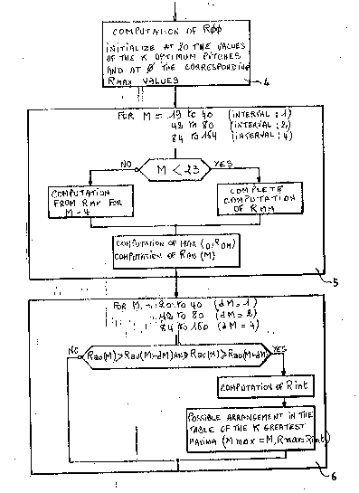
As shown in the steps 4 to 6 in the flow chart of
figure 3, the computation operation consists in
computing three quantities R00, RMM and ROM defined as
follows, wherein the sign ** designates an
exponentiation.
R00=Scc(No)~'c2+Scc(No+4)~2+Scc(No+8)'~2+...+SCC(N~l60)""'2 (9)
RMM=Scc(No-M)~'c~"2+Scc(No+4-M)~d~2+Scc (No+8-M) + . . . +Scc(~ot-
160-M)~ '2 t 10)
ROM=Scc(No) .Scc(No-M)+Scc(No+4) Scc(No+4-~)+ . . +Scc(No+l-
60), Scc(No+160-~l) (11)
For each position No chosen, the quantity R00 is
: computed at the step 4 only once, the quantity RMM is
computed integrally at the step 5 only for certain
values of M and by iteration for the other values, and
:
the quantity ROM i5 computed integrally at the step 5
: for each value of M.
The values of M for which :the self-correlation
: 20 computation takes place correspond to a fundamental
- : :
frequency of ~he speech signal capable of changing
betw en 50 Hz and~400 Hz. These are determined on three
ranges defined as follows: :
Range 1 M-20, 21, 22.... 40 giving 21 values a~ the in~erval 1
;25 Range 2 M=42, 44, 46.... 80 giving Z0 values at the interval 1
Range 3 M=84, 88, 92.... 1~0 giving 20 values at the interval 1
giving a total of 61 different values that can be
encoded or example on 6 bits~with a minimum precision
: :
: ,.'.; ,....... . .. .: ,' ,,.. " - , .
.
, "- . . ...
.:
. .
of 5% corresponding to a half-tone of the chromatic
scale.
The iteration formula used for the RMM computation
is the following:
RMM(M)=Rl~MtM-4)+Scc(No-M)~ 2-Scc(No+164-M)~'2 (12)
Besides, to improve the precision of searching for
the maxima of self-correlation, a parabolic
interpolation formula is used which, for a given value
M, uses the values of the previous quantities for M-dM,
M and M+dm, dM being an interval value equal to 1, 2 or
4 according to the range considered. The result thereof
is that only the values of RMM (19), RMM (20), RMM
(21), and RMM (22) have to be computed integrally. The
: others are computed by iteration, including for M=164.
As a function of the above, a value is computed:
Rau(M) defined as follows:
Rau(M) = 0 if ROM(M)< = 0
~ : and Rau(M) = ROM(M)~:~2/lROO(M).RMM(M)]
:~ ~ if ROM(M)>0 ~ -
- 20 Only the values of M for which a local maximum is
~- obtained, namely those for which Rau(M) verifies the
. inequalities:
Rau(M) > Rau(M-dM) et Rau(M) ~ - Rau ~M+dM)
are considered in the step 6. For these value of M
; 25 only, there is then computed a value Rint interpolated
: parabolically according to the relationship
Rint - Rau(M) + 1i8 [Rsu(~+dM) - Rau(MdM)]~:'2
/ [2.Rau(M) - Rau(M-dM) - Rau(M+dM)] ~13)
- . . .
2 g,~
to keep, in the sequence of the processing operations,
only the K values corresponding to the highest K values
of Rint (and the associated values of M), for example
the biggest K=2 maxima referenced Rmax(1), ..., Rmax(K)
(and Mmax(1), ..., Mmax(K)).
The following part of the processing operation
consists in keeping up to date a table of scores
associated with the different possible values for the
pitch M.
This table, referenced Score (1) in figure 4
contains, for the i=1 to 61 pitch values M, a quantity
that is an increasing function of the degree of
. ,
- likelihood of the associated pitch (from 20 to 160) and
. is updated at each new evaluation of the
self-correlations (typically every 5 to 10 ms), in
ta~ing account of the fact that, from one evaluation to
the next one, the position~s of the maxima may vary by
: more than one unit,~remain stationary or vary by less
than~ one unit~ depending :on whether the pitch is
respectlvely increasing, stationary or decreasing.
The table~of the scores :~is transferred into a
temporary table, marked ExScore(i) that is not shown.
: Thls table is~def1ned;as a function of the values of
as follows~
ExScore (0) = 0~
Exscore (i~ = Score (i) for i = 2
: and Exscore (62) = 0
::
1 3 ~
11
Periodically (if not routinely), the minimum v~lue
is withdrawn to prevent possible overflows in such a
way that:
ExScore (i) = ExScore (i) - ScoreMin (14)
with
ScoreMin = ~IN [Score (20)), Score (21), ..., Score (61)]
The different scores are initialized to take
account of a possible dri-ft of the pitch. This gives:
Sc~re (i) = MAX [ExScore(i-l)) ExScore(i), FxScore (i+l)]
for i = 20, ... , 61
Finally, for the values I(1), ..., I(K) of
corresponding to the K pitches Mmax(1) ... MMax(K)
~: : where maximum values are encountered, the scores are
: increased by a quantity equal to the maxima of the
self~-correlation found such that:
Score (I(K3) ~ Score(I(K):)+Rmax(K)
for k = 1, 2, ..., K.
: and i:=~I(1)~,~ ...,~I(K)
:,
: Finally, the~value M of the pltch chosen for the
:~ position No is the~one corresponding to the maximum of
the:~table of the scores, ScoreMax, located at the index
Imax in this table.~
If,~for~ reasons of computing precision and/or
algorithmic reasons,~several successive values of the
25~ score ~are ;equal to~ the~ maximum ScoreMax, namely
~: : :
score ( Imax? ~ Scoré(Imax+1), Score(Imax+dI), the value
chosen for the ;pitch is the cné that corresponds to
,
'; ' -
:
,
2 ~
12
Imax+[dI/2], [dI/2] being the integer value of the
division dI by 2, as indicated in figure 4.
For a given frame, where the above-described
computations are done several times, the final value of
the pitch is that obtained in the last iteration, it
being understood that there are between 2 and 4
iterations per frame.
The value M of the pitch which is thus obtained
: corresponds to the most likely periodicity of the
speech signal centered around the position N with a
resolution of 1, 2 or 4 according to the range in which
the value of M is located. The voicing rate is then
computed by carrying out a self-correlation,
standardized for a delay equal to M and possibly for
neighboring values if the resolution is greater than 1,
of the original speech signal S(n) and not on the
pre-processed~slgnal Scc(n~ as for the computation of
the pitch.
For example, for M~ = 40, the standardized
. 20 : self-correlation is computed: only for a delay of 30.
,
For M = 40, it is computed:for delays of 40 and 41, and
; for M = 100, lt is computed ~or a delay of 100, but
also for delays of 98, 49 as well as 101 and 102 (the
resolution being 4 for M = 100).
25 ~ In every:case, the chosen value Rm is the greatest
of the values thus computed, an elementary value for M
, ~ ~
~ data elements being defined by the relationships:
, ~
~ R = ROMZ/(R00.RMM~ if ROM is positive
'
:
,
or R = 0 if ROM is smaller than or equal to zero
Roo = S(~o)~'2+S(No+1)~2+ +S(No+160)~2
RMM = S(No-M)~~2+S(~o+l-M)~'r2+.. +S(~o+160-~ 2
ROM = S(No).s(No-M)+s(No+l)~s(No+l-~l)+
+S(No+l6o)~s(No~l6o-M)
Unlike the computation method implemented earlier
to compute the signal S (n), the signal S(n) is not
sub-sampled. cc
The quantity R00 does not depend on M and is
computed only once. It is possible to be limit the
operation to computing RMM for the nominal value of M
only, namely the value given by the method of computing
the pitch as descxibed here above. For values close to
U it is possible to limit the operation to computing
RMM by iteration~if necessary. The quantity ROM should,
on the contrary, be computed for each of the value of
M.
To ~limit the fluctuations, especially in the
~noise-ridden environment of the quantity R thus
obtained, this quantity is filtered by a low-pass
filter;between two success1ve passayes (corresponding
to two successive values of the reference value N ) to
o
obtain a filtered value Rf(P) de~ined at each iteration
p by the relationship:~
~ ~ Rf(P) ~ (1-a) Rf(P~ a.R
- ~ m
; where a is a constant preferably equal to 1/4 or 1/2
~ for the performance characteristics to be satisfactory~
: ::
-.
-
:
' ' . ,
~7~
14
By tolerating an encoding delay, an even moresatisfactory expression may be the following:
-RE(P) = [Rm(P-1)+2Rm(P)+Rm(P~l)]~4
Finally, the quantity Rf(P) is compared, as shown
in figure 5, with two thresholds S and S
V NV
respectively called the voicing threshold and the
non-voicing threshold such that the threshold S is
greater than the threshold S to obtain a binary
NV
- indicator of voicing IV as shown in figure 5.
In figure 5,
the state IV = 1 corresponds to a voiced sound and
: the state IV = 0 corresponds to an unvoiced sound.
; Starting from the state IV = 1, IV goes to the
state 0 when Rf(P) becomes smaller than S and
NV
starting from the state IV = 0, IV goes to the state
:~ :when Rf(P) becomes greater than S .
, - V
Typical values to adjust the two thresholds S
and ~ may:be, for:example, fixed at~S = 0.2 and
V ~ : V
S = 0.05 in taking:l as the ~maximum value of Rf(P)
NV ~ ~ ~
and~O~as the minimum~value:of~:Rf(P). :
In:~order to~ optimize :the : performance
: characteristics:~of the :volo~lng : decision, it is
preferable for~ these thresholds to be adjustable to
give~a certain~ inertia to~ the~decision which is not
: 25: perceptlble to t~e~ear~to prevent local errors in the
appreciation o~ the volcLng. ~ ~
., ~ .
: : ~ :
.
: ~ ,