Language selection

Search

Patent 2057276 Summary

Third-party information liability

Some of the information on this Web page has been provided by external sources. The Government of Canada is not responsible for the accuracy, reliability or currency of the information supplied by external sources. Users wishing to rely upon this information should consult directly with the source of the information. Content provided by external sources is not subject to official languages, privacy and accessibility requirements.

Claims and Abstract availability

Any discrepancies in the text and image of the Claims and Abstract are due to differing posting times. Text of the Claims and Abstract are posted:

  • At the time the application is open to public inspection;
  • At the time of issue of the patent (grant).
(12) Patent: (11) CA 2057276
(54) English Title: DEVICE FOR PREVENTING AIR-SUPPLY OBSTRUCTION
(54) French Title: DISPOSITIF SERVANT A EMPECHER L'OBSTRUCTION DE L'ARRIVEE D'AIR
Status: Term Expired - Post Grant Beyond Limit
Bibliographic Data
(51) International Patent Classification (IPC):
  • E04H 07/22 (2006.01)
  • B65D 88/72 (2006.01)
(72) Inventors :
  • HOLMQVIST, MATS (Sweden)
(73) Owners :
  • PM LUFT AB
(71) Applicants :
  • PM LUFT AB (Sweden)
(74) Agent: NORTON ROSE FULBRIGHT CANADA LLP/S.E.N.C.R.L., S.R.L.
(74) Associate agent:
(45) Issued: 2002-07-02
(22) Filed Date: 1991-12-09
(41) Open to Public Inspection: 1992-08-27
Examination requested: 1998-07-08
Availability of licence: N/A
Dedicated to the Public: N/A
(25) Language of filing: English

Patent Cooperation Treaty (PCT): No

(30) Application Priority Data:
Application No. Country/Territory Date
9100552-0 (Sweden) 1991-02-26

Abstracts

English Abstract


A silo (1) for cereals has channels (4-7) in its bottom (3), the channels (4-
7) being
provided on their upper sides (8-11) with passages for the through-flow of
air, in order
to facilitate emptying the silo (1) through an outlet opening (12). Said
passages have a
tendency to become clogged by dust present in the cereals. In order to prevent
this, the
end of each channel (4) located in the vicinity of the outlet opening (12) is
provided with
one or more openings (17) for the passage of said dust while at the same time
limiting the
air accompanying it to a minimum.


Claims

Note: Claims are shown in the official language in which they were submitted.

3
The embodiments of the invention in which an exclusive property or privilege
is
claimed are defined as follows:
1. A device for preventing air-supply obstruction in order to facilitate
emptying a
silo (1) for cereals, said silo (1) having a bottom (3) and a side wall (2),
the bottom (3)
being so shaped that cereal types located thereon will move towards an outlet
opening
(12), channels or pipes (4-7) being arranged in said bottom (3) for bleeding
off air,
one end of said channels, connected to a supply of air, leading from or in the
vicinity
of the side wall (2) and being directed towards the outlet opening (12), an
other end of
each of the channels (4-7) being located at the outlet opening (12) and an
upper side
(8-11) of the channels (4-7) substantially coinciding with the bottom (3) and
being
perforated or provided with passages of such width that an individual grain of
cereal
cannot enter, wherein the other end of each channel has an opening (17) or
openings
which are sufficiently large to permit any cereal dust that may have collected
in the
channel (8) to pass to the outlet opening (12) while limiting the air
accompanying it to
a minimum.
2. A device as claimed in claim 1, wherein the part (20) of the bottom located
between two channels (4 and 5) is in the nature of a ridge with a sloping
surface on
each side of said two channels (4 and 5).
3. In a silo for cereals where an air supply is employed for aiding the
emptying of
the cereals,
means or preventing obstruction to the flow of air because of dust particle
accumulation,
the silo having a vertical side wall (2), a sloping bottom (3), and an outlet
opening (12) for the cereals,
said means for preventing obstruction to the flow of air comprising:
a plurality of channels (4-7) formed in said sloping bottom, said channels
having two ends and being arranged with one of their ends converging toward
the
outlet opening (12),
said air supply (14, 15) connected to the other ends of the channels,

4
each of said channels (4-7) being covered with means having perforations
permitting the passage of air but inhibiting the passage of cereals,
said means having perforations substantially coinciding with the sloping
bottom, and
a transverse wall (16) near the outlet opening (12) of each of the channels,
said transverse wall (16) having at least one opening (17) sufficiently large
to
permit dust particles collected in the channels to pass but limiting the air
flow to a
small quantity.
4. In the silo of claim 3 wherein the sloping bottom (3) located between the
channels (4-5, 5-6, 6-7) takes the form of a ridge (20, 21, 22) with a surface
sloping
on each side toward the channels.

Description

Note: Descriptions are shown in the official language in which they were submitted.


CA 02057276 2001-08-27
1
A DEVICE FOR PREVENTING AIR-SUPPLY OBSTRUCTION
The present invention relates to a device for preventing air-supply
obstruction. More
particularly the device pertains to a silo having a bottom and side wall. The
silo is
intended for use as a storage container for cereals and is also designed to be
emptied
when required. A known silo has an outlet opening at the bottom and a bottom
which
is so shaped that cereals lying on the bottom will move towards the due to a
sloping
surface. A number of channels are arranged in such a bottom, leading from the
inner
wall of the silo towards its outlet opening. The channels are arranged in said
bottom
and are provided on their upper sides with passages for air. Air is namely
supplied to
the ends of the channels close to the silo wall. The passages in the channels
shall be so
small that cereals are unable to pass through them. When emptying such a silo
is
suitable to supply air to the channels so that the cereals more readily leave
the silo.
However, a problem arises with said channels since the cereals bring with them
a
considerable amount of small particles such as dust and these small particles
have a
tendency to clog the channels so that air cannot pass through them, with the
result that
it can be difficult to completely empty a silo. If the channels are blocked
the
remaining cereals must be removed manually through the outlet opening. It is
extremely hazardous for people to enter a silo in order to empty it. If the
silo is filled
with cereals and refuses to empty, since it is an organic product, it should
be supplied
with cooling air and this is done with the aid of the same channels as those
supplying
air during emptying.
The object of the present invention is to endeavour to avoid said obstruction.
Success
has been achieved in a satisfactory manner by providing the end located
nearest to the
outlet opening, on its transverse end, with openings or an opening and this
should
preferably be located close to the bottom of the relevant channel. Air can
pass through
the opening and takes with it the dust particles present in the channel and
transports
them to the outlet opening. The dust can be removed in a later operation. The
opening
in the channel for said dust should be as small as possible so that a minimum
amount
of air escapes from the channel and does not impede the air flowing out
through the
upper side of the channel.

CA 02057276 2001-08-27
la
Therefore, in accordance with the present invention, there is provided a
device for
preventing air-supply obstruction in order to facilitate emptying a silo for
cereals, said
silo having a bottom and a side wall, the bottom being so shaped that cereal
types
located thereon will move towards an outlet opening, channels or pipes being
arranged in said bottom for bleeding off air, one end of said channels,
connected to a
supply of air, leading from or in the vicinity of the side wall and being
directed
towards the outlet opening, an other end of each of the channels being located
at the
outlet opening and an upper side of the channels substantially coinciding with
the
bottom and being perforated or provided with passages of such width that an
individual grain of cereal cannot enter, wherein the other end of each channel
has an
opening or openings which are sufficiently large to permit any cereal dust
that may
have collected in the channel to pass to the outlet opening while limiting the
air
accompanying it to a minimum.
Also in accordance with the present invention, there is provided a silo for
cereals
where an air supply is employed for aiding the emptying of the cereals,
means or preventing obstruction to the flow of air because of dust particle
accumulation,
the silo having a vertical side wall, a sloping bottom, and an outlet opening
for
the cereals,
said means for preventing obstruction to the flow of air comprising:
a plurality of channels formed in said sloping bottom, said channels having
two ends and being arranged with one of their ends converging toward the
outlet
opening,
said air supply connected to the other ends of the channels,
each of said channels being covered with means having perforations
permitting the passage of air but inhibiting the passage of cereals,
said means having perforations substantially coinciding with the sloping
bottom, and
a transverse wall near the outlet opening of each of the channels,
said transverse wall having at least one opening sufficiently large to permit
dust particles collected in the channels to pass but limiting the air flow to
a small
quantity.

CA 02057276 2001-08-27
1b
The present invention will be described in more detail with reference to the
accompanying two sheets of drawings, in which
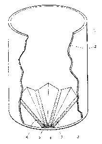
Figure 1 shows a silo,

Figure ? shows an arrangement of channels at the bottom of the silo,
Figure 3 shows a cross section of the bottom of a silo and
Figure 4. shows a channel for air provided with passages on its upper side.
In the drawings 1 is a silo with a vertical wall 2 and a bottom 3. The bottom
3 is
provided with four channels 4, 5, 6 and 7 which have rectangular cross
section, the
upper side of the channels being provided with passages for air. The bottom 3
is
arranged to slop towards the outlet opening 12 which means that all points on
the bottom
3 slope towards the outlet opening 12. The ends of the channels at the inner
wall of the
silo are connected to pipes 14 and 15 which in turn communicate with a common
pipe 13
through which air is supplied to facilitate emptying the silo, or cooling air
to keep the
cereals in the silo intact. The bottom of the silo is designated from 1~ to
22. Each
channel is provided on its upper side with passages, preferably achieved by
the upper
part of each channel consisting of mesh. Figures 3 and 4 show such mesh tops 8
to 11
for the channels 4 to 7. The surfaces 20, 21 and 22 between the channels may
be in the
nature of ridges, as can be seen clearly in Figure 3. Due to these ridges the
upper
surface of the channels will form the bottom of flow furrows for a cereal.
Each channel
is provided at its lower end with a transverse wall 16 with an opening 17 for
dust. This
opening is such that all the dust which collects in a channel is carried to
the outlet opening
whereas the air passing through the opening is reduced to a minimum. The
opening is
2 p thus dimensioned so as to allow through a minimum of air while at the same
time all dust
is removed from the channel.
The provision of said opening 17 in the channels achieves the great advantage
of
eliminating the need for manual emptying of cereal remnants in a silo, and
thereby the
advantage that staff do have not to enter the silo in order to completely
empty it.

Representative Drawing
A single figure which represents the drawing illustrating the invention.
Administrative Status

2024-08-01:As part of the Next Generation Patents (NGP) transition, the Canadian Patents Database (CPD) now contains a more detailed Event History, which replicates the Event Log of our new back-office solution.

Please note that "Inactive:" events refers to events no longer in use in our new back-office solution.

For a clearer understanding of the status of the application/patent presented on this page, the site Disclaimer , as well as the definitions for Patent , Event History , Maintenance Fee  and Payment History  should be consulted.

Event History

Description Date
Inactive: Expired (new Act pat) 2011-12-09
Letter Sent 2010-12-09
Inactive: Late MF processed 2010-12-07
Inactive: Office letter 2007-03-26
Inactive: Corrective payment - s.78.6 Act 2007-01-31
Inactive: IPC from MCD 2006-03-11
Inactive: Reversal of will be deemed expired status 2006-02-16
Inactive: Office letter 2006-02-16
Letter Sent 2005-12-09
Grant by Issuance 2002-07-02
Inactive: Cover page published 2002-07-01
Pre-grant 2002-04-12
Inactive: Final fee received 2002-04-12
Letter Sent 2001-10-30
Notice of Allowance is Issued 2001-10-30
Inactive: Approved for allowance (AFA) 2001-10-17
Amendment Received - Voluntary Amendment 2001-08-27
Inactive: S.30(2) Rules - Examiner requisition 2001-02-26
Amendment Received - Voluntary Amendment 1999-06-30
Inactive: Status info is complete as of Log entry date 1998-07-27
Letter Sent 1998-07-27
Inactive: Entity size changed 1998-07-27
Inactive: Application prosecuted on TS as of Log entry date 1998-07-27
All Requirements for Examination Determined Compliant 1998-07-08
Request for Examination Requirements Determined Compliant 1998-07-08
Application Published (Open to Public Inspection) 1992-08-27

Abandonment History

There is no abandonment history.

Maintenance Fee

The last payment was received on 2000-11-28

Note : If the full payment has not been received on or before the date indicated, a further fee may be required which may be one of the following

  • the reinstatement fee;
  • the late payment fee; or
  • additional fee to reverse deemed expiry.

Patent fees are adjusted on the 1st of January every year. The amounts above are the current amounts if received by December 31 of the current year.
Please refer to the CIPO Patent Fees web page to see all current fee amounts.

Fee History

Fee Type Anniversary Year Due Date Paid Date
MF (application, 6th anniv.) - small 06 1997-12-09 1997-11-25
Request for examination - standard 1998-07-08
MF (application, 7th anniv.) - standard 07 1998-12-09 1998-11-16
MF (application, 8th anniv.) - standard 08 1999-12-09 1999-12-07
MF (application, 9th anniv.) - standard 09 2000-12-11 2000-11-09
MF (application, 10th anniv.) - standard 10 2001-12-10 2000-11-28
Final fee - standard 2002-04-12
MF (patent, 11th anniv.) - standard 2002-12-09 2002-11-13
MF (patent, 12th anniv.) - standard 2003-12-09 2003-11-18
MF (patent, 13th anniv.) - standard 2004-12-09 2004-11-15
MF (patent, 14th anniv.) - standard 2005-12-09 2005-11-17
MF (patent, 15th anniv.) - standard 2006-12-11 2006-11-21
2007-01-31
MF (patent, 16th anniv.) - standard 2007-12-10 2007-11-28
MF (patent, 17th anniv.) - standard 2008-12-09 2008-11-24
MF (patent, 18th anniv.) - standard 2009-12-09 2009-11-09
MF (patent, 19th anniv.) - standard 2010-12-09 2010-12-07
Owners on Record

Note: Records showing the ownership history in alphabetical order.

Current Owners on Record
PM LUFT AB
Past Owners on Record
MATS HOLMQVIST
Past Owners that do not appear in the "Owners on Record" listing will appear in other documentation within the application.
Documents

To view selected files, please enter reCAPTCHA code :


To view images, click a link in the Document Description column. To download the documents, select one or more checkboxes in the first column and then click the "Download Selected in PDF format (Zip Archive)" or the "Download Selected as Single PDF" button.

List of published and non-published patent-specific documents on the CPD .

If you have any difficulty accessing content, you can call the Client Service Centre at 1-866-997-1936 or send them an e-mail at CIPO Client Service Centre.


Document
Description 
Date
(yyyy-mm-dd) 
Number of pages   Size of Image (KB) 
Claims 2001-08-26 2 60
Description 2001-08-26 4 146
Abstract 1994-02-04 1 12
Drawings 1994-02-04 2 42
Representative drawing 2001-10-17 1 11
Description 1994-02-04 2 96
Claims 1994-02-04 1 30
Representative drawing 1999-07-05 1 15
Acknowledgement of Request for Examination 1998-07-26 1 194
Commissioner's Notice - Application Found Allowable 2001-10-29 1 166
Late Payment Acknowledgement 2011-01-25 1 164
Maintenance Fee Notice 2011-01-19 1 171
Late Payment Acknowledgement 2011-01-25 1 164
Correspondence 2002-04-11 2 66
Correspondence 2006-02-15 1 12
Correspondence 2007-03-25 1 12
Fees 1996-11-28 1 49
Fees 1995-11-29 1 59
Fees 1994-12-06 1 59
Fees 1993-11-30 1 45