Note: Descriptions are shown in the official language in which they were submitted.
2~76~8
SPECIFICATION
~AGNETIC LOC~ DEVICE
BACKGROUND O~ THE INVENTION
Field of the Invention
The present invention relates to a magnetic lock device that makes use
of the attracting action of the magnetism.
Description of the Prior Art
A conventional 0agnetic lock device includes a permanent magnet
having a first side for providing one magnetic polarity to which a first
ferromagnetic plate is attached and packaged in a nonmagnetic enclosure,
and having a second side opposite the first side for providing tlle
opposed magnetic polarity to which a second ferromagnetic plate may be
detachably attached, the second ferromagnetic plate having a rod extending
therefrom and adapted to be inserted through the respective bores in the
permanent magnet and enclosure so that the rod can disengageably engage
the first -ferromagnetic plate or the rod extending therefrom. The
conventional magnetic lock devices are used as attachments for handbags,
baggages, and the like, or for clothes, belts, and the like.
According -to the conventional magnetic lock device, -the ferromagnetic
rod on -the second ferromagnetic plate is inserted through the respective
bores in the permanent magnet and enclosure when the first and second
ferromagnetic plates are to be coupled together. When this occurs, the
sliding motion of the second ferromagnetic plate relative to the surface
of the enclosure must be attempted in order to bring its rod into registry
with the bore in the enclosure accurately. Usually, several attempts
2~7698
~nus-t be made until -the two parts are mated successfullY. As those
attempts are repeated each time they are -to be coupled together, -the
surface of the enclosure will be damaged (such as scratches) by -the
sliding motion. There is another conventional 0agnetic lock device that
is primarily designed to eliminate this problem (as disclosed in the
Japanese patent applications Nos. 1-191404 and 2-105503). ~liS magnetic
lock device includes an enclosure which is formed to present a depressed
surface on the side that engages the second ferromagnetic plate.
The last-mentioned conventional magnetic lock device has the construc-
tion that inludes the enclosure having the depressed surface on the
side engaging the second ferromagnetic plate. Thus, when the second
ferromagnetic plate is slided relative to the depressed surface of the
enclosure so that its rod can be brought into registry with the bore in
the enclosure, it may be appreciated that it can be moved along the
depressed surface toward the bore at the center directly, without any
effort to locate the bore randomlY. This can reduce any possible damages
that would occur if the sliding motion would be attempted in -the same
manner as for the earlier-mentioned prior art construction.
SUMMARY OF TXE INVENTION
It is therefore understood that the provision of the depressed
surface on the enclosure provides an effective means for protecting the
enclosure against those possible damages. In this regard, it is an
object of the present inventon to provide a new and improved construction
of the magnetic loc~( device that permits such a depressed surface to be
formed on the enclosure, without affecting the functions of the device.
In its specific form, the magnetic lock device according to -the
2~7~g
present invention includes a permanent magnet having a first side for
providing one magnetic polaritY to which a first ferromagnetic plate is
rigidly attached. The permanent magnet is packaged in a nonmagnetic
enclosure. It also includes a second ferromagnetic plate that is adapted
to be detachably attached to a second or opposite sicle of the permanent
magnet for providing the opposed polarity. The second ferromagnetic
plate has a rod of ferromagnetic material extending therefrom, and the
rod can be inserted through the respective bores in the Permanent magnet
and enclosure. The first ferromagnetic plate may also have a rod of
ferromagnetic material e~tending therefrom. When the rod on the second
ferromagnetic plate is inserted through the bores, it can engage the firs-t
ferromagnetic plate or the corresponsing rod thereon. The nonmagnetic
enclosure has a depressed surface on the side on which the second ~erro-
magnetic plate engages the enclosure, and has a bore at the center of the
depressed surface. The depressed surface is formed on the enclosure
such that there is a magnetic gap between it and the second side of the
yermanent magnet.
Ihe advantage of the magnetic lock device according to the present
invention is that the second ferromagnetic plate can be slided along the
depressed surface formed on the side of the nonmagnetic enclosure that
engages the second ~erromagnetic plate, to ensure that its rod can be
guided directly and accurately toward the bore at the center o-~ the
enclosure.
A further advantage of the present invention is that the nonmagnetic
enclosure having the depressed surface ma~ be spaced away from the second
side of the permanent magnet so that there may be a gap or ma~netic gap
therebetween. Thus, the enclosure may be made of brass or any other
nonmagnetic material that can be machined to the desired shape. ~his
2~57~98
contribu-tes -to the red~ced weigh-t o~ the device as a whole. Fur-thermore,
the manu-facturing process may be simpli~ied with less manu~acturing costs.
BRIEF DESCR~PTION ~F THE DRAWINGS
The above and other objects, features, and advantages of the present
invention will become apparent -from the detailed description of the
preferred embodiments o-f the invention that is provided with re~erence to
the accompanying drawings, in which:
Fig. 1 is a sectional view o~ a ~irst pre~erred embodiment o~ the
present invention;
Fig. 2 illustrates the cross section of the part of the device
according to a second pre~erred embodiment that provides the magnetically
attracting action;
F:ig. 3 illustrates the cross section o-f the magneticallY attracting
part according to a third pre~erred embodiment;
Fig. 4 illustrates the cross section of the magneticallY attracting
part according to a ~ourth preferred embodiment;
Fig. 5 illustrates the cross section o-~ the magnetically attracting
part according to a fi~th pre~erred embodiment;
Fig. 6 illustrates the cross section o-~ the magnetically attracting
part having a depressed surface varying in the profile from those in the
preceding embodiments;
Fig. 7 illustrates the cross section of the magnetically attracted
part of the device according to another preferred embodiment;
Fig. 8 illustrates the cross section o~ the magnetically attracting
part according to a sixth pre-ferred embodiment; and
Fig. 9 illustrates the cross section o~ the magnetically attracting
$
part according to a seven-th preferred embodiment.
DETAILED DESCRIPTION OF THE PREF~RRED EMBODI~ENTS
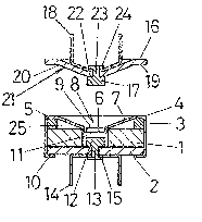
Fig. 1 illustrates the cross section o~ the magnetic lock device
according to the first preferred embodiment thereof. As seen from
Fig. 1, the device comprises two parts, generally designated as A and B.
The part A, which may be referred to as the "magnetically attracting
part", attracts the part B magnetically, which may be referred to as
the "magnetically attracted part". The part A includes a cylindrical
permanent magnet 1 having a central bore 11 extending therethrough, a
flrst ferromagne-tic plate 2 rigidlY attached to a first side of the
permanent magnet 1 for providing one magnetic polarity, and an anmllar
nlember 3 rigidlY attached to a second or opposite side of the permanent
magne-t 1 for providing the opposed polarity. The permanent magnet 1,
first ferromagnetic plate 2 and annular member 3 are packaged in a
nonmagnetic enclosure 4 that may be made of any nonmagnetic material such
as brass.
The enclosure 4 has -the cylindrical shape closed at the top and
open at the bottom, on its top end side, the enclosure 4 is formed to
provide a depressed surface 8 like a funnel, having a peripheral flat
portion 5 resting against the annular member 3, a slanted portion 7
extending downwardly and inwardly from the peripheral flat portion 5
toward the center, and a bore 6 at the center. The center bore 6 is
formed to include an cylindrical extension 9 depending downwardlY -therefrom
like a skirt. On the bottom end side, it includes nails 10, 10 extending
inwardly radiallY for holding the permanent magnet 1 and first ferro-
magnetic plate 2 firmly.
2~57~9~
The extension 9 depending downwardly from the center bore 6 forms a
cylindrical shape which is ~itted inside the center bore 11 through the
permanent magnet 1. The first ferromagnetic plate 2 includes a rod 12
extending into hal~ the dep-th of the bore 11. ~he rod 12 has a sha~t
13 extending downwardly there~rom and which passes through the first
ferromagnetic plate 2. The bottom end o-~ the shaft 13 has a ~lange or
rivet 15 formed by press, extending outwardly radiallY so that it can
hold a pair of mounting legs 14 and secure it to the first ~erromagnetic
plate 2.
The part B, or the magnetically attracted part, includes a second
ferromagnetic plate 16, a rod 17 made also of ferromagnetic material and
extending from the second ferromagnetic plate 16 on the side thereof
facing the part ~, and a pair of mounting legs 18 secured to the second
ferromagnetic pla-te 16 on the opposite side thereo~. The second ferro-
magnetic plate 16 is made of iron, and is formed to include a peripheral
marginal flat edge 19 whose shape conforms to the shape of the correspond-
ing annular flat portion 5 of the enclosure 4, and a slanted portion 20
extending inwardlY radiallY ~rom the peripheral marginal flat edge 19,
the slanted portion 20 forming the protruded sur~ace 21 matching the
shape of the corresponding depressed surface 8 on the enclosure 4. The
protruded surface 21 is flat at the center thereof, as shown at 22,
where a bore is provided for accepting the rod 17. The rod 17 has the
diameter that allows the rod 17 to be inserted into the cylindrical part
9 on the enclosure 4, and the length or height that allows the rod 17
flatly to meet with the corresponsing ferromagnetic rod 12 on the first
ferromagnetic plate 2, when the second ferromagnetic plate 16 is placed
on and magnetically attracted toward the enclosure 4. The rod 17 has
a shaft 23 whose bottom end is formed by press to include a flange 24
~7~8
for holding a pair of mounting legs 18 and securing i-t to the second
~erromagnetic plate 16, in the same manner as described with reference to
the part A.
According to the embodiment of the magnetic lock device described
above, it maY be appreciated that the second ferromagnetic plate 16 ~or
the part B maY be magnetically attracted toward the part A including the
permanent magnet 1 when the plate 16 is placed on the enclosure 4, or
may be detached from the part A by pulling it away from the part A. This
may be accomplished by placing the second ferromagnetic plate 16 on
the enclosure in such a way that the peripheral marginal flat edge 19
and protruded surface 21 of the plate 19 can engage the corresponding
respective annular flat portion 5 and depressed surface 8 of the enclosure
4. `~hen this occurs, the rod 17 from the second ferromagnetic plate
16 can meet the rod 12 from the first ferromagne-tic pla-te 2 at their
respective ends. When those rods meet, the magnetic lines of ~orce
from the permanent magnet 1 are centered onto the rods 12 and 17 through
their respective ferromagnetic plates 2 and 16. Thus, the rods can
attract each other under the action of the centered magnetic force.
More specifically,.the operation may be performed in the following
manner. When the part A and the part B are to be coupled together~ the
second ferromagnetic plate 16 is placed onto the enclosure 4, and its rod
17 maY be inserted into the center bores 6, 11 by sliding it relative to
the top surface of the enclosure 4. By doing this, the rod 17 can be
guided along the slant 7 formed by the depressed surface 8 on the enclosure
4 toward the center bore 6. The minimum amount of effort maY be required
to direct the rod 17 toward the bore 6 by restricting its sliding motion
to the shortest way to the bore 6. In this way, the damges such as
scratches on the enclosure 4 that may be caused by the sliding motion can
2~57~98
be avoided, as i-t is -the case with -the prior art which provides improvemen-t
in this regard.
The annular member 3 is interposed between the permanent magnet
1 and the enclosure 4 so that a gap 25 can be de~ined between the top
side of the enclosure 4 and the polar side of the permanent magnet 1
facing the top side. This gap is functinally equivalent to a magnetic
gap in the magnetic circuit. The total weight of the device can be
reduced by the amount of the gap 25. The annular member 3 has the simple
configuration, and the fabrication process may be simplied by using this
annular member 3. The annular member 3 may be made of either ferro-
magnetic materials or nonmagnetic materials. PreferablY, the annular
member should be made of brass or similar materials that can be cut to
the desired shape. When the annular member is made, anY nonmagnetic
materials, brass, copper, or synther.ic resins may be used. The annular
member may consist of two split parts, each having the identical shape
such as the semi-circular shape, which maY be assembled togther into one
unit.
Figs. 2 through 5 show several respective variations of the preceding
embodiment. In the varia-tion shown in Fig. 2, the magnetic gap 25 in Fig. 1
is filled with another annular member 26 made of brass.
As seen from Fig. 2, the annular member 26 includes a bottom side
26a which engages the second polar side of the permanent magnet 1, and
an upper side 26b whose shape conforms to the shape of the top surface of
the enclosure 4. The annular member 26 may appear to have a slightly
complicated profile, but it can be shaped to the desired profile by using
brass, copper, or synthetic resin materials.
In the variation shown in Fig. 3, the permanet magnet 1 has a
center bore 11 whose upper peripheral edge is cut to provide a slant 27,
2~7~
and the enclosure ~ has a depressed sur~ace 8 that presents a steeper
slant 7 that matches the slant 27. In this variation, the annular member
3 may also be made of either ferromagnetic or nonmagnetic materials.
Fig. 4 shows the variation of the annular member, in which an annular
member 28 has a cylindrical shape and is disposed on the second polar
side of the permanent magnet 1, and the enclosure 4 has the depressed
surface 6 on its top, beginning with the peripheral edge and slanting
downwardly toward the center bore 6.
Fig. 5 shows a further variation o~ the annular member 28 in Fig. 4,
in which the first ferromagnetic plate 2 has a slightly greater in diameter
than that of the permanent magnet 1, and an annular member 29 has a
cylindrical shape which surrounds the permanent magnet 1.
The annular member 28 shown in Fig. 4 may be made o~ either ferro-
magnetic or nonmagnetic materials, whereas the annular member 29 in
Fig~ 5 should be made of nonmagnetic materials.
In each of those specific variations described above, a magnetic
gap 25 may be provided between the permanent magnet 1 and the enclosure 4
on the top side thereof, or a magnetic gap may be provided by the annular
member 26, 28, or 29. This gap reduces the weight, and makes the fabrica-
tion easy. '~hen the annular member is made of nonmagnetic materials,
brass, copper, or synthetic resin material may also be used. The annular
member may also consist of two split pieces.
In the preceding embodiments and the variations thereof, the depressed
surface 8 on the top of the enclosure 4 provides a linearly slanted
surface 7. The depressed surface 8 may provide a curved slant surface 3Q
as shown in Fig. 6.
In each of the preceding embodiments, the second ferromagnetic plate
16 on the part B provides the protruded surface 21 whose shape matches
2 ~ 9 8
-the shape of the depressed surface 8 on tl1e enclosure 4. Alternatively,
the shape may be -flat as shown in Fig. 7. In this case, it is important
to ensure that the rod 1~ ~or the part A and the rod 17 for the part B
can meet each other flatly, when the two parts A and ~ are coupled.
The variation shown in Fig. 5 maY be varied as shown in Fig. 8
and ~ig. 9, respectively.
In Fig. 8, the annular member 29 may be omitted, and instead an
annular member 31 which may be made of ferromagnetic or nonmagnetic
materials may be fitted inside the bore ll through the permanent magnet
1. In this case, the peripheral bottom end 9 of the enclosure 4 that
extends into the bore ll may be supported by the peripheral upper end of
tl1e annular member 31.
In Fig. 9, the peripheral bottom end 9 of the enclosure ~ may be
supported by -the peripheral marginal edge o~ the rod 12.
In Figs. 8 and 91 the enclosure 4 can be also suppor-ted firmly, and
the magnetic gap can be defined between the enclosure 4 and permanent
magnet l. The constructions in Figs. 8 and 9 may provide the same
functional effects as those in the preceding embodiment and variations
thereof.
According to the present invention, the rod ior the magnetically
attracted part can be directed toward the center bore by sliding it
relative to the enclosure when that part is coupled with the magnetically
attracting part, without causing any possible damages such as scratches
on the enclosure during the sliding motion. The gap provided between
the permanent magnet and enclosure reduces the weight and makes the
fabrication easy.
Although the present invention has been described in full detail by
referring to the preferred embodiments and variations thereof, it should
1 0
2~57~9~
be unders-tood that various changes and modifications may be made without
depar-ting from the spirit and scope Olc the invention.
lOa