Note: Descriptions are shown in the official language in which they were submitted.
RBP File No. 6681~001
2 ~ 3 ~
Title: Bacg ~U~G.~ D l~ KNAL FRAME
FI~LD OF THE lNv~NrlON
The present invention relates to the field of
back support units and pro~ides, in particular, a support
unit incorporating a frame that encourages a correct
sitting posture and automatically adjusts to support a
person's lower back.
Rl~ ,R~UND OF T~IE lNVl~ lOM
Stiffness and soreness, especially in the lower
back area, are common ailments of individuals who spend a
great deal of time sitting down. U~ually, these ailments
are due to a combination of poorly designed seating and a
poor posture while seated.
A correct sitting posture re~uires that
individuals be seated with their backs straight and theix
weiqht evenly balanced on their buttocks and thighs.
Unfortunakely, through bad habits or a lack of muscle
strength, many individuals tend to lean on an armrest or
slouch down in their seats. Also the tasks people often
conduct while seated require them to regularly lean
forward, or to one side, to operate a keyboard, reach a
telephone, or operate a vehicle.
It is desirable that a chair or portable support
be provided that encourages people to adopt a correct
sitting posture while allowing them the freedom to move
one way or another.
Along with encouraging people to develop a
correct sitting posture, the seating should support the
curvature of the spine to reduce the back strain
occasioned by sitting for extended periods of time. The
main area where people require support is in the lower
back at the lumbar region of the spine. Stiffness and
sorene~s in the lumbar region is usually a result of the
lumbar curve of the spine having to support a majority of
the weight of the upper body. The larger the individual,
the greater the weight the curve must support. What is
2 ~
required i5 a device that adjusts itself to support the
lumbar curve of the spine according to the upper body size
of the user. The ~upport should be rigid and should not
af~ect the ability of the device to encourage a correct
5 seating posture.
Many forms of back support units have been
developed over the years. Examples of such units may be
seen in U.S. patents: 2,769,485 (Shapiro) and 3,697,133
~Wolofski).
Typically, such units are made from a foam
material that is molded to mimic the curvature of the
average person's spine. Sometimes an S-shaped internal
frame is also provided to mimic the spine. This frame is
usually made from a plastic or fibreglass material. The
curvature o~ the spine varies greatly with the population
however and the molded or shaped units are rarely able to
provide support where it is needed. The support that is
provided is often not rigid enough to support the upper
body weight acting upon the spine. Also, molded foam
matarial and plastic or fibreglass frames tend to break
down and lose their curvature over time to even further
reduce the support provided.
The present invention overcomes these problems
by providing a support unit that incorporates a frame
providing lateral support to encourage a user to adopt a
correct sitting posture and rigid lumbar support that
automatically ad~usts to a user's body size to support the
lumbar region of their back.
SUNNAR~ OF THE lNVh..llON
In one aspect of the invention there is provided
a frame for a back support unit, said frame comprising:
(a) a center portion extending transversely and in
a longitudinal direction,
(b3 a pair of wing portions, said wing portions
extending transversely and forwardly in opposite
directions one from each side of said center
portion,
(c) said center portion comprising a plurality of
column supports spaced apart transversely and
extending in said longitudinal direction,
td) said center portion further including a
plurality of cross members extending
transYer~ely and connected to said column
supports,
(e) at least one of said cross members having a pair
of wing sections extending transversely into
said wing portions, for said wing sections to be
depressed rearwardly when a person sits against
said backrest and for the rearward -v~- ent of
said wing sections to cause said center portion
to bulge forwardly at least ad~acent said one
cross member and hence to assume a convex shape,
such convexity providing lumbar support to said
person.
D~SCRIPTION OF TH~ DRAWINGS
For a better underst~n~ing of the present
invention, and to show more clearly how it may be carried
into effec~, reference will now be made, by way o~
example, to the accompanying drawings, which show a
preferred embodiment of the present invention, and in
: which:
Fig. 1 is a front view of a frame for a back
:: support unit in accordance with the.present invention;
: Fig. 2 is an enlarged view of a clip connecting
a column support to a cross member;
Fig. 3 is a bottom view of one embodiment of the
frame shown in Fig. 1 where the center portion is
generally planar when not in use;
: ~ Fi~. 4 is a bottom view of the frame shown in
:Fig. 3 with the wing portions being pressed rearwardly to
cause the center portion to bow forwardly;
: 35 Fig. 4A is a side view showing movement of a
support column forwardly when the wing portions are
pressed rearwardly;
, , .
-. 2~3r~r41 ~
Fig. S is a bottom view of another embodiment of
the frame shown in Fig. 1 where the center portion has a
slight forward bow while not in use;
Fig. 6 is a perspective partial sectional view
of a portable back support uni~ showing the frame molded
into a padded body;
Fig. 7 is an exploded perspective partial
sectional view of an integral back support unit showing a
back post being secured to a backboard; and
Fig. 8 is an enlarged front view of an upper
part of the center portion of the frame secured by clips
to the backboard.
DESCRIP~ION OlF ~HE PREFERRED EMBODIMENq~
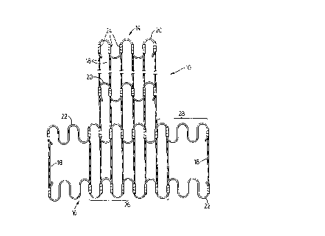
Referrin~ first to Figs. 1 and 6, there is shown
a frame 10 for a back support 12. The frame 10 has a
center portion 14 and a pair of wing portions 16.
The center portion 14 has a greater height than
the wing portions 16 as may be seen in Fig. 1. It is
conceivable however that both portions may have the same
height to provide a frame 10 that is either low, for a
back suppor~ 12 for the lower back only, or high, for a
full height of lateral support.
The center portion 14 is generally planar as
shown in Figs. 1 and 3. Alternatively, the center portion
14 may have a slight convexity as shown at 15 in Fig. 5.
The convexity provides an initial minimum lumbar support
as will be described further below.
The wing portions 16 are each generally planar
and extend forwardly at an obtuse angle from the elongate
sides of the center portion 14. They are provided to give
lateral suppoxt to the support unit 12 and to exert a
torsional force upon the center portion when the unit is
occupied.
The frame 10 is made up of parallel spaced-apart
column supports 18 that extend in a longitudinal
direction. This direction (generally ~ertical) corresponds
generally with the orientation of an individual's spinal
-- 5 --
column, so that the device may mimic its support of the
individual's upper body weight.
The frame 10 also includes upper and lower cross
members 20 and 22 that extend in a transverse direction.
This direction corresponds generally with the breadth of
an individual's thoracic and lumbar regions, so that the
device may mimic the support provided by muscles in these
regions.
The column supports 18 are connected by
connectors 24 to the cross members. A range of connectors
24 can be used, but metal clips 24 as shown in Fig. 2 are
preferred. These clips 24 are crimped about inter~ection~
between the column supports 18 and the cross members. The
column supports 18 are preferably wrapped in paper 25
before being clipped to the cross members to further
tighten the connection and preYent relative mo~ement
between the respective members.
The upper cross members 20 are generally planar
and span the upper end of the center portion 14 of the
frame 10. They are resilient both forwardly and rearwardly
in relation to the ~eneral plane of the center portion 14.
The lower cross members 22 are bent and have a
center section 26 and two wing sections 28. The wing
sections 28 extend at an obtuse angle a (Fig. 3) from the
ends of the center section 26. An angle ~ of 135~ is
preferred. The lower cross members 22 are also resilient
forwardly and rearwardly in relation to the general plane
of the center portion 14. The win~ sections 28 thus cause
the frame 10 to be of generally concave appearance as
viewed from its front.
Preferably, he wing sections 28 are integral
with their corresponding center section 26, although it is
conceivable that they may be distinct and immovably
attached to the center section 26. Alternatively, it is
conceivable that there may be a ratchet attachment tnot
shown) between the wing sections 28 and their
corresponding center section 26. A ratchet attachment
would provide fixed resistance when the wing sections 28
are depressed rearwardly in relation to the general plane
of the center portion 14. It is conceivahle th~t such
ratchet attachments could be releasably locked to vary the
obtuse angle between the wing sections 28 and the center
section 26. This would allow the wing portions 16 of the
frame 10 to be ad~usted to provide a more precise lateral
support conforming to each individual's needs.
The wing sections 2~ of the lower cross members
22 act as torsion bars upon their corresponding center
- section 26 when a person rests against the back suppor~
12. The torsional forces cause the center section 26 to
become convex forwardly (as shown at 26a in Fig. 4) in
rela~ion to the plane of the center portion 14 when the
wing sections 28 are depressed rearwardly. The wing
sections 28 would be depressed when an individual rests
against a back support 12 incorporating the ~rame 10.
The column supports 18 extending along the
center portion 14 are closely spaced and preferably
parallel. They act to transfer the convexity imparted upon
the center section 26 along a portion of the longitu~in~l
extent of the center portion 14. The plane of the center
portion 14 thus acquires a convexity in a txansverse
direction adjacent the wing portions 16. This convexity is
transferred through the bacX support 12 to engage the
lumbar region of an individual's lower back, when the
individual is resting against the support unit 12.
Nhile the center sections 26 of the lower cxoss
members 22 have a convexity formed in them when a user
leans against the back support, the upper cross members 20
L~- ~in largely planar. This causes the central column
supports 18 t~ move from a generally vertical position to
the forwardly slanted position shown in phantom lines at
18' in Fig. 4A. However, the column supports 18 remain
generally straight during this -,v~- -nt.
While it is preferred that the column supports
are straight, it is conceivable that they could have a
curve imparted along their length. This curve could mimic
the curvature of the spine, if desired.
The column supports i8 extending along each of
the wing portions 16 are preferably parallel and spaced
further apart than the column supports 18 extending along
the center portion 14. This ensures that the wing portions
16 are not too rigid and thus optimizes their function as
torsion bars.
The cross members 22 are preferably formed from
tempered wire. This wire has a long lasting resiliency and
an enhanced "memory". It has been found that plastic or
wooden frames loose their resiliency over time and thus
provide reduced lumbar support. The cross members shown in
Fig. 1 have a lateral, continuous S-shaped configuration
that is well suited for translating the torsional forces
that are placed upon the wing sections 28.
The column supports 18 may thus be attached by
the clips 24 at the points where the lateral S-shaped
cross member is parallel to the column support. The center
por ion 14 of the frame 10 shown in Fig. 1 is thus formed
with six column supports 18 along its center portion 14
and two column supports 18 along each of its wing portions
16.
The wing portions 16 of the frame 10 preferably
have a height of approximately 18-19 centimetres. For such
a height, two lower cross members 22 are preferred to
provide optimum lateral and lumbar support. The height of
the center portion 14 may be varied to provide frames for
high and low backed supports 12. For a low back support
the center portion 14 preferably has a height of
approximately 40 centimetres. For such a height, two upper
cross members 2a are sufficient. A frame 10 for a high
back support 12 would have three upper cross members 20
and a height of approximately 53 centimetres.
The frame 10 is molded into the back support
unit 12 by encasing it with a padding 30 and a cover 32 as
may be seen in Figs. 6 and 7. The padding 30 is preferably
~ ~ v j~ r~
made from a high density foam that is firm and long
las~ing. A range of cover materials may be made from any
appropria~e cloth or other material. The frame 10 is
oriented wi~hin the support unit so that the lower part of
the center portion 14 will correspond with the lumbar
region of an individual's back while sitting against the
unit.
The back support unit shown in Fig. 6 is a
portable unit while the back support unit shown in Fig. 7
is ~or an integral unit that forms the back of a chair.
As may be seen in Figs. 6 and 7, the back
support unit ha~ an upper back portion 32 and ~wo side
portions 34. The side portions 34 are generally
~ranslations of the wing portions 16 of the frame lO,
although they may be molded to form a gradual arc from the
upper back portion 32 as depicted in Fig. 6. This provides
a comfortable lateral side support for the back unit that
does not overly restrict sideward motion such as may occur
when driving a car or reaching to one side of a chair.
The cover 32 is preferably glued to the foam
padding 30. The upper back portion 32 of the back support
unit 12 has ears 36 as shown in Fig. 6 that allow the
cover 32 to be centered before being drawn over the
padding 30 containing the glue. Otherwise, the cover 32
would be difficult to install because of the tendency of
the glue to dry quickly.
The integral back unit depicted in Fig. 7
includes a backboard 38 that is attached to the frame 10
by fastener~ 40 at the upper end of the center portion 14
as may be seen in Fig. 8. The backboard 38 is then molded
into the padding 30 of the back support unit and thus
hidden from view. The lower portion of the backboard 38 is
not fastened to the frame lO and thus the center portion
14 of the frame 10 is free to become convex when the win~
portions i6 are pressed. With the addition of the
backboard 38, the back support 12 may be secured to a back
post 42 of a chair. The back post 42 may be attached to
the backboard 38 through the back of the back support 12
using attachments 44 such as screws or T-nuts. A
fabricated foam strip 46 may be provided to fill the space
between the top of the back post 42 and the re~ ing
upper back portion 32 of the back support 12.
It is understood that preferred embodiments of
the invention have been described and that changes and
alternative embodiments may be made within the spirit of
the invention as defined by the appended claims.