Language selection

Search

Patent 2057730 Summary

Third-party information liability

Some of the information on this Web page has been provided by external sources. The Government of Canada is not responsible for the accuracy, reliability or currency of the information supplied by external sources. Users wishing to rely upon this information should consult directly with the source of the information. Content provided by external sources is not subject to official languages, privacy and accessibility requirements.

Claims and Abstract availability

Any discrepancies in the text and image of the Claims and Abstract are due to differing posting times. Text of the Claims and Abstract are posted:

  • At the time the application is open to public inspection;
  • At the time of issue of the patent (grant).
(12) Patent Application: (11) CA 2057730
(54) English Title: ELASTIC TRUCK FOR ROLLER SKATES
(54) French Title: CHARIOT ELASTIQUE POUR PATIN A ROULETTES
Status: Deemed Abandoned and Beyond the Period of Reinstatement - Pending Response to Notice of Disregarded Communication
Bibliographic Data
(51) International Patent Classification (IPC):
  • A63C 17/00 (2006.01)
(72) Inventors :
  • CHEN, TING-HSING (China)
  • CHEN, TING-HSING (China)
(73) Owners :
  • FAR GREAT PLASTICS INDUSTRIAL CO. LTD.
(71) Applicants :
  • FAR GREAT PLASTICS INDUSTRIAL CO. LTD. (Taiwan, Province of China)
(74) Agent: ADE & COMPANY
(74) Associate agent:
(45) Issued:
(22) Filed Date: 1991-12-16
(41) Open to Public Inspection: 1993-06-17
Examination requested: 1991-12-16
Availability of licence: N/A
Dedicated to the Public: N/A
(25) Language of filing: English

Patent Cooperation Treaty (PCT): No

(30) Application Priority Data: None

Abstracts

English Abstract


ABSTRACT OF THE DISCLOSURE
An elastic truck for roller skates includes
two brackets being located on center top portion of a
front and a rear beams, respectively, and shaped like a
bowl having their recess surfaces facing upward, two
bosses having respective flanges near top portion,
being integrally formed to the underside of the
baseplate facing downwardly with one boss located
behind the front beam and the other one located before
the rear beam, respectively, and two semispherical
elastic balls having respective circular grooves close
to top portion thereon and respective blind holes at
center portions therein. Wherein when a skater stands
on the baseplate or when skater is making turns and
jumping, the elastic balls and the blind holes will
deform to absorb the vibration caused by such movement
to maintain stability for skater.


Claims

Note: Claims are shown in the official language in which they were submitted.

I CLAIM:
1. An elastic truck for roller skates comprising
two brackets shaped like a bowl being
integrally formed on the center top portion of
respective axle hubs having respectice recesses facing
upwardly, two bosses integrally formed to the underside
of the baseplate of a skate facing downwardly with one
boss located to the rear of the front beam and one boss
located to the front of the rear beam, and having
respective bores, and two semispherical elastic balls
being mounted to said respective bosses 10 and having
bottom portions disposed outwardly of said bosses and
seated on top of said respective brackets.
2. An elastic truck for roller skates according to
claim 1, wherein each boss has a flange at top inner
portion thereon; and wherein each semispherical elastic
ball has a circular groove closed to top portion
thereon to engage with respective flanges of respective
bosses, and a blind hole at top center portion therein.

Description

Note: Descriptions are shown in the official language in which they were submitted.


- 2~5773~
TITLE: AN ELASTIC TRUCK FOR ROLLER SKATES
FIELD OF THE INVENTION
This invention relates to thc general art of
roller skate structure. More particularly, the present
5 invention relates to a stabilizer truck used in
conjunction with roller skat~.
BACKGROUND OF 'rHE INVENTION
There has been an overall heightened awareness o~
maintaining stability for a roller skater. It i~
especially difficult for a professional skater who
requires to perform a lot of jumping, turning,
spining... etc..
The prior art of trucks enable skater to do a easy
performane. But when skater requires to perform a
complicated skating skill, the trucks would be
difficult to maintain the stability of the skater.
The inventor has therefore, invented the present
invention which is more stable than prior art.

` 2~773~
SUMMARY OF THE INVENTION
It is the primary object o~ the present invention
to ~rovide an elostic truck for roller skates which
is a second shock absorbing device to skater.
It is another object of the present invention to
provide an elastic truck ~or roller skates which is
more stable for skater.
It is still another object of the present
invention to provide an elastic truck ~or roller
skates which has better mar.uveribility.

~1~5~73~
BRIEF DESC~IPTION ~F THE DRAWINGS
FIG. 1 is a perspective view of the present
invention partially exploded;
FIG. 2 is a side sectional view of FIG. 1;
FIG. 3 is a side sectional Yiew of FIG. 2 showing
a force being applied on the skate
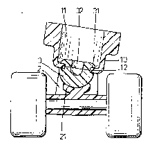
FIG. 4 is a ~ectional view of FIG. 3 taken along
line A-A illustrating the manner in which a skater
leans to one side in order to effect turning; and
FIG. ~ is a same view of FIG. 4 illustrating the
skater leans to another side to effect the turning.

~ 2~77~0
DETAILED DESCRIPTION OF THE P~E~ERRED EMBODIMENT
Referring initially to FIG. 1, the present
invention having a baseplate 1, two beams 2 bein8
integrally formed at their top ends to the underside of
the baseplate 1 with one at the front and one at the
rear portions, respectively, two bosses 10 integrally
formed to the bottom portion of the baseplate 1 facing
downwardly with one located near the rear portion of
the front beam 2 and another one located near the front
portion of the rear beam 2. Two axle hubs 22 are
connected to the bottom end of re~pective bePms 2 and
extending perpendicularly thereto. On the middle top
portion o~ each of the axle hubs 22, there i9
integrally formed two brackets 21, each havin a
recess surface facing up~ardly. Each boss 10 hss a
through bore 11 and a falnge 12 at its top inner
portion. Two semispherical elastic balls 3, e8ch
defines a blind hole 32 at top center portion and a
circular groove 31 near top end being sized to allow
the flange 12 of the boss 10 to be inserted therein.
Upon each elastic ball 3 is placed to respective bosses
10, the flange 22 of each boss 10 is inserted into each
circular groove 31 and the bottom portion of each ball
3 below the groove 31 is disposed underneath each boss
10 and seat on the recess surface of respectiver
brackets, as shown in FIG. 2.

2~57730
It is to be noted that each flange 12 is so
inserted into the groove 31 o$ each semispheri~al b~ll
31 that when a skater is standing on the baseplate l,
the ball 3 will only deform because of the skater's
weight and will not depart from the boss 10.
upon a skater steps on the baseplate 1, the front
beam 2 will move backwardly, and the rear bean Z will
move forwardly. Both move~ents of the beams 2 limit
some upward flexing force. The remaining upwsrd
flexing force shall be trans~erred to the e1astomeric
b~lls 3. When the brackets 21 pushes the balls 3
upwardly, the balls 3 and the blind holes 32 will
de~orm to absorb the f7exing force, ~s shown in F~G. 3.
FIG. 4 is a sectional view illustrating a skater
leans to his left side. The left side of the ball 3
and the blind hole 32 are deformed in order to absorb
the pressing force resulting from the weight shiftiDg
and to effect the left turn.
In like manner, when skater's weight is shifting
from left side to the right side of the skate, as shown
in FIG. 5, the right side of the ball 3 and the blind
hole 32 are deformed in order to absorb the pressing
force resulting from weight shifting and to effect the
right turn.

Representative Drawing
A single figure which represents the drawing illustrating the invention.
Administrative Status

2024-08-01:As part of the Next Generation Patents (NGP) transition, the Canadian Patents Database (CPD) now contains a more detailed Event History, which replicates the Event Log of our new back-office solution.

Please note that "Inactive:" events refers to events no longer in use in our new back-office solution.

For a clearer understanding of the status of the application/patent presented on this page, the site Disclaimer , as well as the definitions for Patent , Event History , Maintenance Fee  and Payment History  should be consulted.

Event History

Description Date
Time Limit for Reversal Expired 1995-06-18
Application Not Reinstated by Deadline 1995-06-18
Deemed Abandoned - Failure to Respond to Maintenance Fee Notice 1994-12-16
Inactive: Adhoc Request Documented 1994-12-16
Application Published (Open to Public Inspection) 1993-06-17
Request for Examination Requirements Determined Compliant 1991-12-16
All Requirements for Examination Determined Compliant 1991-12-16

Abandonment History

Abandonment Date Reason Reinstatement Date
1994-12-16
Owners on Record

Note: Records showing the ownership history in alphabetical order.

Current Owners on Record
FAR GREAT PLASTICS INDUSTRIAL CO. LTD.
Past Owners on Record
TING-HSING CHEN
Past Owners that do not appear in the "Owners on Record" listing will appear in other documentation within the application.
Documents

To view selected files, please enter reCAPTCHA code :


To view images, click a link in the Document Description column. To download the documents, select one or more checkboxes in the first column and then click the "Download Selected in PDF format (Zip Archive)" or the "Download Selected as Single PDF" button.

List of published and non-published patent-specific documents on the CPD .

If you have any difficulty accessing content, you can call the Client Service Centre at 1-866-997-1936 or send them an e-mail at CIPO Client Service Centre.


Document
Description 
Date
(yyyy-mm-dd) 
Number of pages   Size of Image (KB) 
Drawings 1993-06-16 3 57
Abstract 1993-06-16 1 17
Claims 1993-06-16 1 19
Descriptions 1993-06-16 5 87
Representative drawing 1998-09-27 1 8
Fees 1993-09-13 1 33