Note: Descriptions are shown in the official language in which they were submitted.
- 2Q57921
" ,
T37 960/IA 1 24April 1991
FLOATING ROOF OF SYNTHETI C MATERIAL FOR STOR~GE TAN~
The lnventlon relates to a method for the installation of a
floating roof structure in a closed liguid storage tank and
further lt relate~ to a floatlng roof obtained thereby.
In vlew to steadlly increaseing requirements in environmental
legl81atlon for the storage of volatile liquid products it
becomeq a tendency to avold the creation of a level of liquid
underneath the floating roof as such creation could give rise
to ~ubstantlonal envlronmental problems.
8torage tanks for liquld products may have a diameter from
e.g. 8 to nearly 88 meters and in the latter case enormous
volume of liquld vapour must be dlscharged to the open alr.
Thls encounters extenslve envlronmental problems because
mostly 8uch stored volatlle llqulds dangerously affect the
breathlng of human being8 and animals.
Metal floatlng roof structures are known whlch may sink down
as a result of llquld movements and/or leakage, resultlng
agaln ln the creatlon of a level of liquid. Also there do
exl8t floatlng roofs whlch are underneath covered wlth an
alumlnlum foll yet glvlng rlse to locally created levels of
llquld, causlng the aforementloned dlsadvantages. Moreover a
floatlng tank roof structure must be sufflciently strong to be
usable as a bullding site for carrying out repair activities.
~ ,
Accordlng to the invention a floating roof structure, also
serving as a bullding floor may be installed in a closed
storage tank for liquid, which roof is composed of a number of
lnterconnected synthetlc modules thereby carrylng out the
following steps:
- , . : . . , .: . , . ;, , , -
2~579~
,
T37 960/IA 2 24April 1991
: . .
a. a great number of fully enclosed sandwich module board
elements of reinforced synthetic material, provided with a
core of hard foam and also being locally provided with insert
pieces of screwable material, are lengthwise so positioned
that they constitute altogether an uninterrupted flat working
floor surface, whlch by providing of corresponding roundings
for the tank wall, will correspond in its shape and its size
wlth the floating roof to be installed, whereas thls working
floor l~ supported, at least for a substantial part, by a
temporary and premounted flat horizontally positioned roof
support scaffolding structure which is located underneath and
at a certaln distance from the tank bottom;
b. at the upper side of the working floor and in a direction
whlch ls perpendlcular to the longltudinal axis of sandwich
module boards there are posltloned a number of oblong
transverse frame proflles which are fixedly connected to the
qandwlch module boards by means of fasteners thereby provlding - ~.
for a stlff lntegral roof structure;
c. thereafter the roof structure is provided with operatlonal
means ~uch as: ., ;'
l. a manhole ln order to carry out actlvlties underneath the .:.
roof structure;
ll. at choice a number of roof structure supporting legs,
whlch may or may not be ad~ustable;
lll. a number of cable bushings for the use of antl- .
rotatloncables to prevent an undeslrable rotation of the roof
structure; .:.
lv. at cholce a number of dralnages for condense llguid; ,; .
v. at cholce a number of air inlet and air discharge means; :
whereafter the horizontal roof support scaffolding structure .
l~ dlsmounted and taken out of the tank allowing the floating
roof structure to rest upon its own supporting legs or to rest ~:
upon a number of fixed supporting legs which were installed ;
before on the bottom of the tank; :;~
.
2057921
T37 960/IA 3 24April 1991
d. the longltudinal and traverse seams between adjacent
modules of the working floor for the roof structure are sealed
off at the bottom side of the roof structure by means of self-
adhesive tape thereby formlng a totally flat surface,
whereafter for the prevention of gas and air inclusions, the
seam sllt ls further filled up with synthetic material of the
6kln materlal of the sandwlch module, the self adhesive tape
bel~g removed or not after hardening;
e. the flexlble tank wall seal ls thereafter mounted to the
clrcumferentlal edge of the roof structure. In a preferred
embodlment of the lnventlon the floating roof structure ls
bullt up of sandwlch module boards and traverse frame
proflles, characterlzed ln that a traverse frame proflle has
a polygonal vertlcal cross sectlon and ls composed by two
pre~erably rectangular tubular proflles, one on top of the
oth~r, partlcularly a lower sguare tubular profile and on top
o~ it an upper rectangular tubular proflle,-restlng upon lts
~hort rectangular slde.
It 1~ effective to bulld up the tank roof structure accordlng
to stlll another embodiment of the lnvention with a number of
cut-off proflle~ each time having a length of at least two
time~ the wldth of a sandwich module is applied for, in such a
way that every time the utmost ends of the lowermost square
tubular profiles and also the utmost ends of the upper
rightangled tubular profiles are always located in the central
portion of the sandwich module. It appears that for easy
handling the length of a cut-off profile preferably amounts
1,000 mm whereas the total integral cross section of the
traverse frame profile amounts to 50 x 50 and 50 x 30 square
mm respectively.
Thereby the stiffness of the built up tank roof structure may
be efficiently obtained while uslng a standard sandwich module
having a width of 500 mm, a length of 6,000 mm and a thickness
of 50 mm.
.
,
.
2057921
T37 960/IA 4 24April 1991
In order that a sandwich module possesses sufficient rigidity
it may be provlde in a direction perpendicular to its
longltudlnal axis with integral insert pieces of screwable
materlal at regular distances preferably made of hard
~crewable polylamlnated wood (Multlplex), which pieces are
lncorporated ln the foamed core material for the fixlng of
screws and suchllke flxlng elements in and to the sandwlch
module.
Accordlng to the lnventlon at lts bottom side, the tank roof
~tructùre 15 entlrely flat except for the presence of a
requlred manhole flange and varlous bushings (for cables, alr
lnlets, alr outlets, supportlng legs) respectlvely 50 that lt ::
i8 vlrtually lmposslble that spaces are created having a level
of ll~uld. At the one hand the floating tank roof structure i5
llght enough to float upon the level of liquid whereas at the
oth~r hand lt ls pertlnently unslnkable, thls embodlment of
lt~ structure constltutes such a rlgldlty that no llquld
volume~ are collected upon the tank roof and thus no '::.
unallowable vaporlzatlon wlll occur. By uslng a great number
of ad~u~table support legs provlded for underneath the
flo~tlng tanX roof structure, the entlre roof structure ls
equally ~upported on varlous locations wlth respect to the
bottom of the storage tank and all provlsions are avallable to
make the operatlonal use of the tank roof structure
profltable, thereby excludlng any dlsadvantages whlch ;. :;:
lnherently affect exlstlng floating tank roof structures. ::
According to another embodiment of the invention there are
provided alr lnlet and air discharge means for a tank roof
structure conslsting of a potshaped housing, having a number
of parts, provided with at least one fixing flange for
connecting it with the opening in a sandwich module and a cup .
shaped cover of the housing being provided with a number of
air inlet and discharge openings respectively which are :` :
covered by a flexible non-return valve, a vertically movable
bar being centrally positioned in the cover, which bar is
, .
,;
20~7~21
T37 960/IA 5 24April 1991
provlded at its upper end above the cover with an eyelet for
eonnection to a cable and within the housinq under the cover
and perpendicular thereto said bar is provided with a number
of elosed discs, each having an outer circumferential
downwardly directed cupshaped edge, whereas the inner side of
sald housing is provided with a number of corresponding
downwardly dlrected funnel-shaped concentric baffles, in such
a way that vapors passing through said means are forced to
eseape via this labyrinth seal.
Also aeeording to the invention there is provided for in a
~ermanent fixation by means of a magnet keeping the floating
roo~ ~trueture in plaee by means of anti- of the tank by means
of anti-rotation eables eharaeterized in that a flat magnet is
~rovided having horizontally and eentrally respectively in at
least two mutually perpendieular directions a number of anti-
tlltlng elements, one and the other sueh a way that a possible
tlltlng polnt or tllting line with respeet to said is located
substantlally far away and outwardly from the utmost
borderllne of the elreumferential edge of the permanent magnet
whlch hold~ to the bottom of the storage tank.
The lnventlon wlll now be further deseribed wlth reference to
the accompanylng drawlng of an embodlment shown at dlfferent
scale dlmenslons.
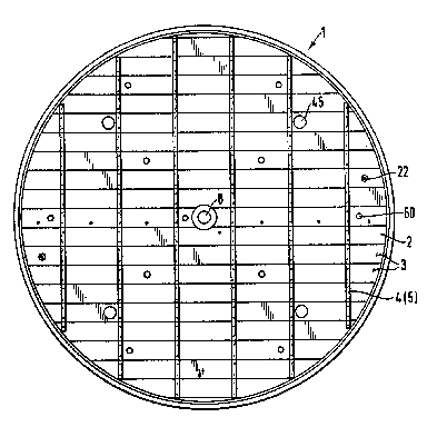
Plg. 1 ls a sehematie upper view of a floating tank roof
strueture aeeording to the invention;
" .
Fig. 2 shows sehematlcally and in cross seetion the loeation
of the tank roof structure which is supported upon the bottom
of the tank by means of a great number of support legs;
Fig. 3 shows separately a synthetie module as part of the flat
surface of the tank roof;
" :
, :"
2057921
T37 960/IA 6 24April 1991
Plg, 4 is partially a cross section through a preferred
embodiment of the tank roof structure taken at the sealing off
agalnst the wall of the tank;
Fig. 5 also shows a partial cross section of another preferred
embodiment of a tank roof structure as shown in Fig. 4;
Flg, 6 i~ a cross section of the traverse frame profiles which
are applled for to render the reguired stiffness and
strongness to the tank roof structure;
Fig. 7 show~ a special anchoring structure to fix the position
of the floating tank roof; ; ~
' '~:'. .
Flg. 8 l~ a cros~ sectlon of a bushing in the tank roof in
use for a dipstlck gauglng tube and for anti-rotation cables;
Plg. 9 ls a eross section of a sampling deviee provided for in
the tank roof, provided with a star-shaped flexible non-return
valve;
Flg. 10 ls a llguid vapour-overpressure drain valve provide
wlth a labyrlnth seal avoiding liquid to arrive upon the tank
roof;
Flg. 11 is a eross seetion of the manhole structure for the
tank roof.
Aeeordlng to the invention the method basically eonsists in
the eomposition of an entire floating tank roof 1, shown in ; ;
Fig. 1 and 2, which has a flat synthetic board covering 2
having floating properties. The strongness and the stiffness
of the synthetic covering 2 is obtained by interconnecting a
great number of sandwich modules 3 to form a flat surface
while using traverse frame profiles 4, each of which is
constituted by a number of tubular, preferably rectangular
;,
I ,
~0~7~21
,................................................................. . ..
T37 960/IA 7 24April 1991
profiles 5, which are traversally coupled to the sandwich
modules 3 ln a special manner.
Prlor to bulldlng up a floatlng tank roof 1 at the inside of a
storage tank 6 there is erected upon the bottom 7 of the tank,
at a workable level of e.g. 80 cm, a scaffolding having a flat
upper surface ~not shown here) upon which the sandwich modules
3 are posltloned. After completion of the tank roof structure
thl~ scaffolding must be dismounted and finally be carried
away through the manhole 8. Upon this flat supporting surface
all sandwich module~ 3 are now horizontally positioned
according to Pig. 1 and nearby the wall 9 of the tank the
sandwlch modules 3 are adapted to the rounded shape.
Internally these sandwlch modules 3, see Fig. 3, are provided
wlth a foamed core material 10 whlch i8 composed from e.g. a
flat core of hard foam sandwiched between two glass fiber
relnforced outer ~kins 11. It is obvious that the sandwich
module 3 is entirely unsusceptible for affection by the
llguld stored in the tank 6; this being important in the event
of mechanical damage to the tank roof structure. The thlckness
o~ the sandwlch module 3 ls e.g. 50 mm whereas the outside
~lmenslon of a single, preferably rightangled, ln the drawing
shown sguare proflle 5, embodiment amounts to 50 x 50 mm.
Plgs. 4 and 5 ~how the arrangement of the traverse frame
profiles 4 in a direction perpendicular to the longitudinal -
axis of the oblong sandwich module 3. One tubular profile 5
which has a rectangular cross section, having an overall
length of e.g. 100 cm, i8 bondwise placed upon a flrst lower
row of tubular proflles 5, see Fig. 6, and it is effective to
let the longitudinal seam 12 between ad~acent sandwich modules
3 coincide with a~ abutting seam 12' between the square
profiles 5. It is advantageous for obtaining a greater
reslstance against bending to compose a traverse frame profile
4 from a lower square tubular profile on top of which in an
upright position, a narrower rightangled tubular profile is
positioned. The traverse frame profile is a reversed T-profile ;
composition; dimensions 50 x 50 mm and 50 x 30 mm
~', :' "',
:,, '':
2~57~21 ~
T37 960/IA 8 24April 1991
respectively. At the one hand installation takes place with
short standard lengths, at the other hand it simplifies a
qulck mountlng and disassembly respectively. In the hard foam
core material of a sandwich module 3 and upon regular ;
distances there is integrally incorporated an insert piece 13
of hard screwable material such as polylaminated wood
(Multiplex), which will stand the fixation of fixing elements,
llke screws 14.
After all preparations have been made and the tank roof `-
~tructure has been completed, all longitudinal and traverse
seams 12 between ad~acent sandwich modules 3 must be sealed
off again~t liquid. To that purpose the seams 12 are now at
the bottom sid~ of the tank roof structure entlrely sealed off
wlth ~elf- adhesive tape and than these seams are filled up
from the top slde with the same materlal of which the skin
coverlng 11 is made. After hardening out there is created an
integral roof which fulfllls all required properties with
respect to lts own floating power. The self-adhesive tape may
be removed after hardening out of the fllled out seam, however
thls ls not always necessary.
After the tank roof structure has been completed, the sealing
15 must be lnstalled its construction belng here descrlbed in
a global way only. In Fig. 4 an endless seallng llp 16 is
llquid tlght connected by means of a collar 17 to the edge of
the tank roof 1 and the position of the tank roof 1 is defined
also by a spring element 18 the one end 19 of whlch is
connected to a seal llp 16 whereas the other end 20 is flxed,
through a spring loop 21, to the tank roof 1. Fig. 5 shows
another wall seal in cross sectlonal vlew, consisting of a
flexlble bumper 16' whlch ls flxed to the tank roof 1 by means
of a dlstance holdlng devlce 18'. Flg. 7 shows a bushlng 22 in
the sandwich module 3 for an anchorlng cable 23. The upper end
of this anchoring cable 23 is fixed to the fixed roof of the
storage tank 6 and its lower end 24 is connected to the upper
side of a permanent magnet 26 by means of a spring 25. It is
2~7921
T37 960/IA 9 24April 1991
the purpose to anchor the magnet 26 to the bottom 7 of the
tank, the presence of a number of anti-rotation cables 23
thereby holding the position of the floating tank roof 1. The
magnet 26 is provided with protrusions 27 e.g. from strip
materlal whlch is fixed to the body of the magnet 26 by means
of clamping or the like thus bringing the tilting point far
away from the permanent magnetic surface, thereby guaranteeing
the permanent location of the magnet 26 with respect to the
bottom 7 of the tank. The extra advantage of this facility,
which 18 unbreakably connected to the tank roof structure, is
the total avoidance of socalled hot spotwelding to the bottom
7 of the tank.
In Flg. 8 another bushlng 28 ls shown for a fixed gauging tube
~not shown here). A flexible collar or cup 29 is clamped
between a flxed flange 30 whlch ls bolted by means of bolts
14' around an openlng ln the tank roof 1 and a removable
flange 31 so that the tank roof 1 can move in an upward and
downward directlon wlth respect to the flxed gauglng tube. If
necessary, the whole tank roof 1 may be sunk for half of lts
thlckness lnto the llquid wlthout affecting its effectiveness.
Por taking liquid samples from the storage tank there ls
provlded a sampling devlce, Plg. 9, consisting of a funnel-
shaped mouth 33 for receiving and centering a bottle shaped
container (not shown) whlch is lowered by means of a star-
shaped cut flexible valve 34 to sample liquid from the tank
content. The annular protruding edge 35 at the lower side of
the funnel-shaped mouth 33 rests upon and is guided
respectively in u tubular passage 36, provided with a flange
37 and a counter flange 38 for its attachment to the opening
in the tank roof 1. At the level of the flange 37 there are ; ;
provided in the tubular widened portion a number of air
openings. The valve 34 is attached to the throat of the
funnel-shaped mouth 33 by means of a hinge 39 and can be ~
opened by means of a cable 40. The other cable end is ;
connected to a hook 41 which is ad~ustably in its height
""., ~,...
2~7921 ;
T37 960/IA 10 24April 1991
attached to the tank roof 1. The valve 34 is automatically
opened ln the event that the lower end of the hook 41 (not
fully shown) is running up against a stop, e.g. the bottom 1
of the tank.
If as a result of weather conditions e.g. liquid vapour is
colleeted under the tank roof 1 which must be discharged,
there are a number of dischargers 32 provided upon openings in
the tank roof 1, see Fig. 10. A discharger 32 consists of a
pot- shaped housing 42 whlch is downwardly attached to a
tubular passage 45 provlded with attachment flanges 43 and 44
res~eetlvely and connected to the tank roof 1. The passage 45 ~ ;
has alr openlngs 46 and lt dlverges downwardly to a funnel 47.
The hou~lng 42 18 eovered by a cup-shaped lid 48 whieh is
~rovlded with passage ways 49 which are closable by means of a
flexlble non-return valve 50. A eentral rod 51 havlng an
eyelet 53 can be operated by a eable 23' from the upper slde
and 80 be llfted or elosed. Attached to the rod 51 and to the
houslng 42 are eoo~eratlng labyrlnth baffles and dlscs 54 and
55 respeetlvely which obstruct the escape of vapour. To enable
a ~ast escape however the lld 48 i8 operated by means of the
cable 23'. ;
,
Plg. 11 shows detalls of a manhole. The manhole cover 56 rests
upon a tubular collar flange 57 circumferential edge of the
manhole 8. The flange is attached by means of screws 14'
screwed ln the hard polylaminated (Multiplex) material wlthln
the sandwleh module 3. In the eentral portion upon the manhole
eover 56 there is a passage opening in which a discharger 32,
see Flg. 2, ean be installed and further handgrips are ;
~rovided at the upper and bottom side respectively of the
manhole eover 56.
~ , .
Flg. 2 sehematically shows the adjustable support legs 60
whieh are guided by and attached to the tank roof 1 by means
of tubular guidings 61. At choice such support legs may have a
j fixed length and are attached to the tank roof 1 by means of a
-~;. ,
20~792~
T37 960/IA 11 24April 1991
tubular guiding 61 or the support legs 60 and their guidings
61 are provided of adjustable locking devices, known per se.
The floating tank roof 1 is of very light construction and it
has a hlgh floatlng power and, by its enormous own rigidity
resulting from the use of sandwich modules and low traverse
frame profiles, ls also an ldeal building floor for carrying
out malntenance activities. The smooth surface underneath it
prevents all existing disadvantages with known tank roofs.
Con~idering the very small height of the tank roof 1, e.g. 50
mm of the ~andwich module plus two times 50 mm for the
composlng tubular profiles 5 of the traverse frame profile 4,
lts total helght ls no more than 15 cm (1) at the location of
the~e traverse frame profiles 4.
In Plg. 1 the ~lmple and systematlc building up of the tank
roof structure by the new method is made visible. The modular
arrangement makes lt posslble to make tank roofs of different
dlmenslons having the same favorable floating power. The use
of the sandwich structure having a hard outer skin make no
longer a problem of possible damages and thelr quick repalr.
Slnce the constructlon ls reallzed with simply operable
sandwlch modules and whereas the tubular proflles are easlly
handled durlng mountlng and demountlng because of the small ~ ;
length, thls novel method offers great advantage~ and extra
safety for the envlronment, now that even for very great tanks
only a mlnlmum evaporatlon will occur and so it remains
controllable. Apart therefrom this floating roof together with
lts synthetlc sandwlch modules has a specific heat insulating
function for the liquid which is stored in the tank.
' "
,~",',','',,
:. "~' " '
..,; . ,
,,~ "
. '~