Note: Descriptions are shown in the official language in which they were submitted.
PCT/CB90/0~832
W O 90/14020 2a!5829~
-- 1 --
M~IERIAL SUCH AS lo~AQc~
The invention relates to the processing of inhRm~geneousmaterial such as leaf tobacco.
Essentially, preparation of cured tobacco leaves involves
stripping the lamuna frcm the stem by a mechanical threshLng
process followed by classifying and separation of the lam m a
frQm the stem parts of the leaf. Both parts are then
processed separately before subsequent manufacture of tobacco
products. It is essential that the separated products conform
to the high standards in respect of extracted lamina particle
size and percentage of acceptable stem content within that
extracted lamuna. Also, from the commercial point of view,
naximum yield of both lamlna and stem from the whole leaf is
required.
According to the invention (which is defined m the claLms)
there is for example provided a methcd of prcgressively
threshing the whole tobacco leaf to liberate the lamina from
the stem of the leaf. After each threshing stage the free
lamina is prograssively separated from the threshed product by
first separating the particles having a larger surface
area-to-weight ratio fm m those having a smaller surface
area-to-weight ratio by their inertia which are pneumatically
classified to extract the lamina by bein~ transversely moved
into a series of controlled velocity streams of gas such as
~;r. Each gas stream is individally adjusted to control
velocity for naxim~m entrainment of the ste~-free lamina in
the area-to-weight ratio group it is classifying. The
penultimate gas stream velocity can be adjusted to increase
the quantity of lamina extracted with the penalty of m creased
stem content of that lamLna, this product beLng then
PCT/~B90/00832
W O 90/14020 v~ 2-
~(~58~90
reclassified in the ultimate gas stream to reduce the stem
content but retain the increased lamina e~traction rate and
therefore classifier efficiency.
Also, according to the invention there ls provided a threshing
machine having a roll-away case giving total access to the
moving and stationary parts of the mach~ne, thereby
facilitating adjustment of clearan oes between these parts to
optimise the threshing performan oe of the machine.
F~lrthermore according to the invention there is provided a
classifier separating the lamina from stem and stem with
lamina attached, oqmprising a plurality of inertia and
pneumatic separating chambers in series, coTprising a modular
constructed enclosure for each chamber, means for providing a
classilying gas flow in each chamber, means for projecting the
threshed particles transversely to the direction of gas flow
therein, means for controlling and adjusting the velocity of
the gas flow, neans for separating and collecting lamina from
the gas flow path via an airlock-oontrolled ou~let, means for
collecting and removing the heavy particles ~stem and lamina
with stem attached) from the chamber and conveying them to the
next threshing stage. Preferably, the gas from which the
lamina has been separated is returned directly to contin~e the
classifying gas flow.
Conventional processing installations thresh the leaf
progressively and between threshing stages use ~nel~matic
classifiers to progressively extract clean lamina from the
threshed mixture, i.e. it is always the 'dirty' product which
is classified and reclassified. The method of the invention
effectively extracts the maximum amount of 'clean' lamina in
such pneumatic classifier cham~ber allowing the rem~ining
'dirty' product to pass to the next stage of threshing. Given
ZC!5829~3 PCT/GB90/00832
W ~ 90/14020 3
this maximum percentage of clean lamuna extrac*ed in chambers
other than the last will be cDntamunated with a unacceptable
amount of stem, this contaminate~d lamina is reclassified to
reduce stem content of the lamina collected from the last
chamber but retain the high percentage extr.action rate.
An embodiment of the invention will now be descri~ed by way of
example with reference to the drawings, in which:
Fig.l shows a tobacco threshing and classification line in
elevation
Fig.2 shows the primary thresher partly in eleva~ion ani
partly in section
Fig.3 show a second3ry thresher
Fig.4 shows a classifier in elevation
Fig.5 shows the preliminary inertial classifying portio~s
of the classifier shown in Fig. 4 on an enlart~ed
scale, and
Fig.6 shows the main, pneumatic classifying portions
of Fig.4 on an enl æ ged scale.
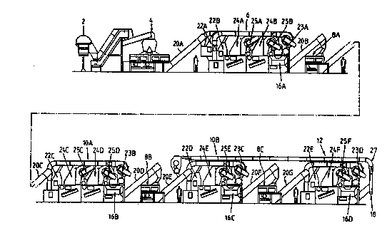
The threshing and classifying line is shown in outline in
Fig.1. An infeed hopper 2 receives the tobacco leaf which is
metered to the primary threshing unit 4. The outlet of the
thresher 4 is linked, by a conveyor belt within housing 20A,
to a first modLlar classifier assembly 6, fm m which the
'clean' lamina is removed on a transverse conveyor belt 16A.
Conveyors within housings 20B-G link alternate threshers aA-C
and classifiers lOA & lOB and final classifier 12. Separated
PCT/GB90/00832
W O 90/1~020
ZC!58~9~
lamina is removed from each classifier on transverse belts
16B, 16C and 16D, a~d the stem is extracted from the final
classifier at exit 18.
The prim2ry threshing unit 4 is shown in Fig.2 and co~prises
t~o threshers since it has to handle the entire throu~lput of
produce. The inccming product to be threshed is divided
between the two threshers by means of a flow divider 29a
formed by tw~ contra-rotating ribbed drums within the infeed
hopper 29. A rotor in each thresher carries fixed blades 30
and is mounted for rotation on a shaft 32 which in turn is
mounted in bearings at each end in the base structure of the
thresher and carries at one end a pulley by means of which it
is driven in rotation by motor 33 through a belt 31.
Adjustment of the tension of each belt 31 is achieved by a
screw and nut assembly which enables the motor and its pulley
to be moved horizontally.
As the blades 30 of each rotor rotate, they pass between them
sets of stationary blades 37 which are pivotally mounted on
the support fra~e of the thresher to enable them to be swung
out for cleaning and maintenance.
Beneath each rotor and adjacent to the paths of the rotor
blade tips is a fixed basket 34 between the bars of which the
threshed product drops to falls onto a conveyor belt 39 which
in turn delivers the product onto a conveyor belt 36a of an
elevator 36. The specific design of the basket depends on the
type of tobacco being processed.
The thresher 4 thus operates in an essentially conven~ional
m2nner and strips the tobacco leaves into portions which
consist partly of pure lamina material, partly pure stem
material and the relElin~er consisting of portions of lamina
Z ~ 5~ 9 n PCT/CB90/00832
W O 90/14020
--5--
material still attached to portions of stem material.
The thresher differs from conventional construction in that
the enclosure for each rotor, instead of being formed by a
fixed enclosure with access doors (which in view of the
considerable width of many installations cause difficulties
due to their weight and m any case restrict access), as its
major portion 38 supported by mçans of rollers 40 on upper and
lower tracks 42a, b on the thresher frame. Thus, whenever it
is required to gain access to the interior of the thresher,
the complete casing 38 or an upper or lower part 38a or 38b
can be rolled aside, thereby providing ready access for the
entire interior for example to enable adjustments. As shown
in Fig 3, each of the later threshers 8A, 8B and 8C has only a
single rotor and one drivm g motor. The movable part 38 of
the casing is shDwn in full lines in its open position and in
dotted lines in its closed working position where it is
secured to the fixed part 40a of the cas m g at the right-hand
side of the rotor. Suitable interlocks prevent the thresher
dkiving motors from operating when the casing is open.
Alternate elevating conveyors within a hDusing 20A, 20C, 20E
and 20G lift the output material frcm the respective threshers
4, 8A, 8B and 8C into the inlet of the respective next
classifier lOA, lOB, lOC, lOD. Each classifier 10 is
assembled from standard sub-units or m~dLles so that the
nLmker of classifications to be carried out within each
classifier can be chosen as required. Fig. 4, b~ way of
example, shows the classifier lOA. This class;fier h s tw~
prelimun~y classification steps 22A and 22B and a full
classification step 24A with a lamina - reclassifi Qtion s~ep
24B.
Fig.5 shows the elements of a prelim m ary classification stase
,.
PCT/CB90/00832
W O 90/14020 6-~
2(:!S8;~90
22. The incQming material to be classified is supplied to the
inlet 101 of an impeller 102 in which a rotating paddle wheel
103 projects the material across an enclosure 104. The paddle
wheel 103 rotates within the casing 105 of the L~peller 102
with a snall clearance so as to form with it an alrlock in all
rotary positions.
A fan assembly 107 mounted at one side of the upper end of the
classifier has a fan 108 (the impeller of which is driven
through a belt 109 by a motor 110) which draws air into its
inlet from the upper end of the enclosure 104 through a duct
112 and a rotating cylindrical screen 113. This air is
returned from the outlet of the fan through a duct 115 leading
into the lower part 116 of the interior of the classifier.
The fan thus causes a relatively gentle uFdraught through the
enclosure 104 past the outlet of the impeller 102. The air
velocity in this region can be adjusted by m~ans of a plate
117 hinged at its upper edge 118 and fIxed in position by
suitable clamping means tnot shcwn). A windDw 119 in the
casing forming the enclosure 104 enables the operation of this
prelimunary classifier to be inspected. In operation, the
components of the product having a low weight to surface area
ratio are entrained in the upward air flow and drawn into the
duct 112 to be deposited on the surface of the cylindrical
separator 113 and thereafter deposited through an ~;r lock 121
onto the transverse oonveyor 16.
The particles having a sQmewhat greater weight to surface area
ratio travel under their momentum across the enclosure to
enter the inlet 102 of the next classifying stage which may be
however a further prelimLnary classifier or a main classifier
24 to be described ~elow. m e articles of the highest
weight-to-surface area ratio, such as stem carrying no lamuna,
2 ~8.~.9 ~ PCT/GB90/00832
W O 90/14020 7
fall through the upward a1r flow and are deposited onto a
conveyor belt 52 on which they are carried to be dep~sited on
the elevating conveyor 36 leading to the next thresher 8.
Fig.6 shows in elevation t~o successive n~in classifying
stages. The intermediate product consistil~g of scme stem and
so~e lamina leaf material enters the left-hand stage 24a at
201 where in falls into the paddle roller 203 of an impeller
202 (which may in fact be the impeller 102A of Fig.5). The
product is thus ejected into the interior of an enclosure
defined by a lower casing 205 and an upper casing 206. Air is
drawn upwards within the upper casing 206 by a fan and an air
product separator assemble 207 of essentially the same
construction as that sh~wn at 107 in Fig.5. H~wever, the
returning air from the fan is directed by a conduit 208 into a
plen~m chanber 209 formed with a series of parallel outlets
210 beneath an inclined conveyor 211 having a slatted conveyor
belt 212 through which ~;r can pass frcm the outlets 210.
This air then passing through the material which falls onto
the belt and can carry away ligh~ particles which were trapped
by heavier particles.
The speed of airflow upwards through the belt 212 and the
interior of the casing 206 is adjusted to be sufficient to
carry substantially all of the free lamm a and those portions
of stem which carry appreciable areas of lamina material. The
portions of stem which carry no or little lamLna, however,
remain on the belt 212 and drop off onto the conv~yor 52.
~b nalntain relatively constant air flow speeds across the
interior of the casing 206, it is found preferable to include
one or possibly tw~ internal baffles 214. The baffle(s) is
(are) located in the interior of the casing to provide a
uniform gas flow across the width of the interior of the
W O 90/14020 -8- PCT/CB90/00832
Z~5829Q
casing.
The product which is entrained in the upward a r flow wi~hin
the Gasing 206 is deposited by the assembly 207 through its
airlock-forming outlet paddle roller 221 into the inlet 301 of
the next classifying stage 24B. This is of identical
construction to the stage 24A being built up from similar
m~dules 205 and 206. The output paddle whe~1 321 of the
second stage delivers lamlna material to the required
specification onto the transverse conveyor 16. The conveyor
311 of the second stage delivers product having a high stem
content onto the conveyor 52 and thence to the elevating
conveyor 36 which delivers it into the next thresher to be
re-threshed.