Language selection

Search

Patent 2058307 Summary

Third-party information liability

Some of the information on this Web page has been provided by external sources. The Government of Canada is not responsible for the accuracy, reliability or currency of the information supplied by external sources. Users wishing to rely upon this information should consult directly with the source of the information. Content provided by external sources is not subject to official languages, privacy and accessibility requirements.

Claims and Abstract availability

Any discrepancies in the text and image of the Claims and Abstract are due to differing posting times. Text of the Claims and Abstract are posted:

  • At the time the application is open to public inspection;
  • At the time of issue of the patent (grant).
(12) Patent: (11) CA 2058307
(54) English Title: METHOD OF FORMING CABLE-GUIDING OPENINGS IN METAL WALL-STUDS AND HAND POWERED TOOL FOR IT
(54) French Title: METHODE DE PERCAGE D'OUVERTURES POUR LES CABLES DANS LES MONTANTS METALLIQUES ET OUTIL MANUEL CONNEXE
Status: Term Expired - Post Grant Beyond Limit
Bibliographic Data
(51) International Patent Classification (IPC):
  • B26F 1/32 (2006.01)
  • B21D 31/02 (2006.01)
(72) Inventors :
  • SZULC, ANDRZEJ J. (Canada)
(73) Owners :
  • TEXTRON INNOVATIONS INC.
(71) Applicants :
  • TEXTRON INNOVATIONS INC. (United States of America)
(74) Agent:
(74) Associate agent:
(45) Issued: 1996-05-07
(22) Filed Date: 1991-12-23
(41) Open to Public Inspection: 1993-06-24
Examination requested: 1993-12-17
Availability of licence: N/A
Dedicated to the Public: N/A
(25) Language of filing: English

Patent Cooperation Treaty (PCT): No

(30) Application Priority Data: None

Abstracts

English Abstract


A method and hand powered tool for forming openings
in metal wall-studs thereby to receive electrical
cables, which can be easily pulled through these
openings. The tool comprises pyramid-shaped piercer
attached to a jaw which is pivotally connected to
a handle having affixed hollow die. The piercer,
pushed into stud's wall by lever, forms in the stud
an opening having guiding tabs shaped from material
displaced from the area of said opening.


Claims

Note: Claims are shown in the official language in which they were submitted.

The embodiments of the invention in which an
exclusive property or privilege is claimed are
defined as follows:
1. A method of forming an opening in a metal wall-stud
and forming tabs about the hole as guides for fished-in
electrical cables, comprising
providing a hand tool having a handle with a hollow
die affixed to one end and a handgrip on another
end, a jaw with a piercer affixed thereto having
pyramidally shaped working end, the piercer co-
operating with the hollow die so as to cut and
deform tabs in the wall-stud, a support affixed
to the handle at a position intermediate the
handgrip and hollow die and having means for
pivotal connection to said jaw with said support
extending above said handle so that the pivotal
connection is spaced away from the handle,
a lever, extending from a second handle and
equipped with a handgrip, means for pivotally
connecting said lever to said jaw and a link
having one end pivotally connected to the handle
and another end pivotally connected to the lever,
squeezing the handgrips together to cause the jaw
to pivot about the pivotal connection on the
support and the piercer and hollow die to coope-
rate with one another to initially puncture the
metal stud in the central area of intended
opening with following tearing of the material
of said metal stud
followed by partially separating the material of
the said stud in the area of the opening, and
shaping the separated material into circumferen-
tially placed triangular-like tabs.
- 6 -

2. A tool for forming an opening in a metal wall-
stud and forming tabs about the hole as guides for
fished-in electrical cables, comprising:
a handle with a hollow die affixed to one end
and a handgrip on another end;
a jaw with a piercer affixed thereto having
pyramidally shaped working end, the piercer
cooperating with the hollow die so as to cut
and deform tabs in the wall-stud;
a support affixed to the handle at a position
intermediate the handgrip and the hollow die
and having means for pivotal connection to
said jaw with said support extending above
said handle so that the pivotal connection
is spaced away from the handle;
a lever, extending from a second handle and
equipped with a handgrip, and
means for pivotally connecting said lever to
said jaw;
a link having one end pivotally connected to
the handle and another end pivotally
connected to the lever,
whereby, when the tool's hand grips are squeezed
together, the lever forces the piercer into material
supported by the hollow die metal wall-stud, thereby
resulting in forming an opening.
- 7 -

Description

Note: Descriptions are shown in the official language in which they were submitted.


2()58307
S P E C I F I C A T I O N
The present invçntion relates to a method of
making openings in sheet metal such as wall-studs
and to tools for making openings.The openings
have to be made for pulling in (fishing in)
electrical cables, during construction or reno-
vation works.Metal wall-studs are manufactured
with three round and three rectangular openings,
however, these openings become often covered by
electrical boxes or by other studs or metal
channels (runners) supporting said boxes. These
runners have no openings at all.
Presently, for making openings in studs, a
tool called "stud punch" is commonly used. This
tool makes round holes similar to those punched
in stud factory. Unfortunately,all the openings
have one common,undesirable feature:their edges
are sharp like knife.This defect proves that the
method of making openings by punching is improper.
The cables pulled through punched openings are
usually aluminum-armoured cables. Their armour is
made of aluminum ribbon wound on electrical wires.
Each coil of said ribbon has arrowhead-like shape.
This feature allows the cable to be fished in
only in one direction.Despite observing this rule,
pulling armoured cable through many openings is
difficult. Pulling back such a cable is almost
impossible.Other kinds of cables, as thermostat
cables or burglar-alarm cables are also pulled in
through punched holes, and their plastic jacket
can be easily damaged by sharp edges.
- 1 - ~
: ,

2~ 307
, ~
Presently used stud punch,imported from abroad, is
rather heavy and awkward to carry tool.It employs
typical couple of dies,which have to be perfectly aligned ^-
to make clean cuts.The required precision contributes
to the tool's price.The small disc of metal,cut out
from stud,has to be picked up from the floor or swept
to garbage bin and eventually deposited in land-fill
site.Another disadvantage of stud punch is that this
tool requires a lot of space to engage it.When addi-
tional supporting studs are present in close proximity,the punch can not be used,unles the stud is unscrewed
and/or twisted,what is not always possible,but always
time-consuming.The punching is impossible when two studs
are joined "back to back". All above mentioned diffi-
culties and problems can be avoided or solved by uti-
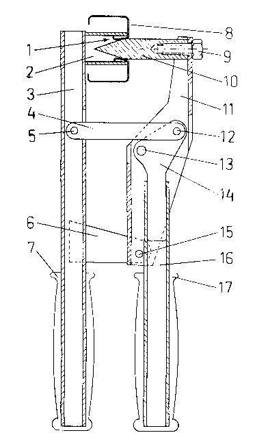
lizing the present invention shown by FIG.l.
BRIEF DESCRIPTION OF THE DRAWING
FIG.l shows an articulated hand tool of the invention
for forming openings in metal wall-studs and forming
tabs about the opening.
DESCRIPTION OF THE PREFERRED EMBODIMENT
The recommended method for making an opening in metal
stud is piercing it with specially shaped piercer 10,
having prismatic shank with pyramidally shaped working
end.After the sharp tip of pyramid pierces the initial
point in the stud 8, the pyramid's edges tear stud's
metal, forming it in triangular-like tabs 1. Simulta-
neously to tearing metal, the pyramid's surfaces
(between edges) bend said tabs, rolling and placing
them around formed in this manner opening.
.... ...
,. ~

3 ~ 7
Further movement of the piercer forces the tabs'
tips against inner walls of hollow die 2.Finally,
small part of prismatic shank enters the opening,
flattening slightly the rolled tabs, especially
at their bases, thus forming the tabs as guides
in said opening.
Such formed guides allow the armoured cable
to be pulled through several openings with ease;
pulling the cabel back is also easy, therefore
electrical job can be done fast. And there is
no damage to plastic-covered cables.
The piercer 10 can be made of steel bar having
crossection in shape of hexagon, pentagon or
square. The sides of pyramid, made by (for
example) milling, should correspond with sides
of prism. The more edges pyramid has, the more
tearings in material have to be done, thus more
force is required to push piercer, therefore
square-based pyramid milled from square bar
seems preferrable. Square opening in stud can
be easily enlarged using pliers, if such rare
need occurs. Smaller openings can be done as
well, simply by closing tool only half-way.
The hollow die 2 can be made of pipe or
hollow structural shape, like square tubing.
It's shape is not critical, since it's diameter
or lateral dimension should be significantly
bigger than thickness of co-operating piercer.
There is no need to observe exact alignment
._ .. ~r
.
' s

~ 2~83~7
between hollow die and piercer; thanks to this
feature, the cost of manufacturing this tool
can be low.
According to features of the invention, there
is provided a tool of compact shape and light,
easy to carry, as shown in Fig.l.
The hollow die 2 is welded to handle 3, which is
made of sguare tubing. This handle houses one
end of link 4, pivotally connected to said
handle by bolt 5. Support 6 is welded to handle
3, too. The jaw 11 is pivotally connected by
bolt 15 to support 6 and can be pushed towards
handle 3 or retracted from it by lever 14, which
is pivitally connected to jaw 11 by bolt 13.
The lever 14 is connected pivotally to link 4
by bolt 12. At it's end, the jaw 11 is connected
to the piercer 10 by scre~,9. The lever 14 is
extended by handle 16. Both handles 3 and 16
are equipped with rubber or plastic handgrips
7 and 17.
The design of this tool allows it to be
engaged also on two studs which are joined
(screwed) together "back to back". Usually,
such studs have their factory pre-punched holes
misaligned. The opening can be pierced only
through one sheet of metal, therefore factory
pre-punched hole should be used as a place to
pierce adjacent stud. The same design of this
tool allows it to pierce a stud in opposite
-- 4
_ _ ..... . .
. . .~, .
- ~
: :, -~ -:
-. :- . . -:

2~83~7 ~
. .
direction, shaping tabs outward of the stud.
The opening can be done also on a side wall of
a wider stud, particularly if one or more small
holes are needed, for example, for tie-wire.
The tool can be easily inserted and used
between studs located closely to each other,
because only piercer or hollow die needs to be
inserted between such studs. It is possible
thanks to grouping all force-transmitting
elements in zone between piercer-die couple
and handgrips.

Representative Drawing
A single figure which represents the drawing illustrating the invention.
Administrative Status

2024-08-01:As part of the Next Generation Patents (NGP) transition, the Canadian Patents Database (CPD) now contains a more detailed Event History, which replicates the Event Log of our new back-office solution.

Please note that "Inactive:" events refers to events no longer in use in our new back-office solution.

For a clearer understanding of the status of the application/patent presented on this page, the site Disclaimer , as well as the definitions for Patent , Event History , Maintenance Fee  and Payment History  should be consulted.

Event History

Description Date
Inactive: Expired (new Act pat) 2011-12-23
Letter Sent 2007-09-25
Inactive: Office letter 2007-08-23
Inactive: Adhoc Request Documented 2007-08-23
Inactive: Office letter 2007-05-31
Inactive: IPC from MCD 2006-03-11
Letter Sent 2005-04-05
Inactive: Late MF processed 1998-12-21
Inactive: Office letter 1998-10-27
Inactive: Office letter 1998-02-17
Letter Sent 1997-12-23
Grant by Issuance 1996-05-07
All Requirements for Examination Determined Compliant 1993-12-17
Request for Examination Requirements Determined Compliant 1993-12-17
Application Published (Open to Public Inspection) 1993-06-24

Abandonment History

There is no abandonment history.

Fee History

Fee Type Anniversary Year Due Date Paid Date
MF (patent, 6th anniv.) - small 1997-12-23 1997-12-30
Reversal of deemed expiry 1997-12-23 1997-12-30
MF (patent, 7th anniv.) - small 1998-12-23 1998-12-21
MF (patent, 8th anniv.) - small 1999-12-23 1999-12-10
MF (patent, 9th anniv.) - small 2000-12-27 2000-12-08
MF (patent, 10th anniv.) - small 2001-12-24 2001-12-21
MF (patent, 11th anniv.) - small 2002-12-23 2002-12-12
MF (patent, 12th anniv.) - small 2003-12-23 2003-12-11
MF (patent, 13th anniv.) - small 2004-12-23 2004-12-21
Registration of a document 2005-02-24
2005-12-02
MF (patent, 14th anniv.) - small 2005-12-23 2005-12-02
MF (patent, 15th anniv.) - small 2006-12-25 2006-11-30
2006-11-30
Registration of a document 2007-04-25
MF (patent, 16th anniv.) - standard 2007-12-24 2007-11-30
MF (patent, 17th anniv.) - standard 2008-12-23 2008-12-01
MF (patent, 18th anniv.) - standard 2009-12-23 2009-12-01
MF (patent, 19th anniv.) - standard 2010-12-23 2010-11-30
Owners on Record

Note: Records showing the ownership history in alphabetical order.

Current Owners on Record
TEXTRON INNOVATIONS INC.
Past Owners on Record
ANDRZEJ J. SZULC
Past Owners that do not appear in the "Owners on Record" listing will appear in other documentation within the application.
Documents

To view selected files, please enter reCAPTCHA code :


To view images, click a link in the Document Description column. To download the documents, select one or more checkboxes in the first column and then click the "Download Selected in PDF format (Zip Archive)" or the "Download Selected as Single PDF" button.

List of published and non-published patent-specific documents on the CPD .

If you have any difficulty accessing content, you can call the Client Service Centre at 1-866-997-1936 or send them an e-mail at CIPO Client Service Centre.


Document
Description 
Date
(yyyy-mm-dd) 
Number of pages   Size of Image (KB) 
Abstract 1993-11-02 1 10
Cover Page 1993-11-02 1 11
Claims 1993-11-02 2 29
Abstract 1996-05-07 1 14
Drawings 1993-11-02 1 16
Description 1993-11-02 5 120
Cover Page 1996-05-07 1 16
Description 1996-05-07 5 149
Drawings 1996-05-07 1 21
Claims 1996-05-07 2 64
Representative drawing 1998-09-01 1 19
Notice: Maintenance Fee Reminder 1997-09-24 1 119
Maintenance Fee Notice 1998-02-03 1 179
Notice: Maintenance Fee Reminder 1998-09-24 1 118
Late Payment Acknowledgement 1998-12-30 1 170
Notice: Maintenance Fee Reminder 1999-09-27 1 130
Notice: Maintenance Fee Reminder 2000-09-26 1 119
Notice: Maintenance Fee Reminder 2001-09-25 1 131
Notice: Maintenance Fee Reminder 2002-09-24 1 118
Notice: Maintenance Fee Reminder 2003-09-24 1 114
Notice: Maintenance Fee Reminder 2004-09-27 1 123
Courtesy - Certificate of registration (related document(s)) 2005-04-05 1 105
Notice: Maintenance Fee Reminder 2005-09-26 1 119
Notice: Maintenance Fee Reminder 2006-09-26 1 118
Notice: Maintenance Fee Reminder 2007-09-25 1 130
Courtesy - Certificate of registration (related document(s)) 2007-09-25 1 129
Notice: Maintenance Fee Reminder 2008-09-24 1 120
Notice: Maintenance Fee Reminder 2009-09-24 1 120
Notice: Maintenance Fee Reminder 2010-09-27 1 121
Fees 2002-12-12 1 103
Fees 2003-12-11 1 111
Fees 1997-12-30 1 33
Correspondence 1998-10-27 1 5
Fees 1998-12-21 1 25
Fees 2001-12-21 1 130
Fees 1997-12-30 2 107
Fees 1999-12-10 1 105
Fees 2000-12-08 1 112
Fees 2004-12-21 1 42
Correspondence 2007-05-31 1 10
Correspondence 2007-07-03 2 67
Correspondence 2007-08-23 1 16
Correspondence 2007-09-18 1 44
Fees 1998-12-22 1 25
Fees 1998-10-22 1 64
Fees 1998-02-23 3 150
Correspondence 1997-12-30 1 16
Fees 1996-11-06 3 87
Fees 1995-12-14 1 30
Fees 1993-12-07 1 17
Fees 1992-11-17 1 16
Prosecution correspondence 1996-02-20 1 51
Examiner Requisition 1995-02-23 1 47
Courtesy - Office Letter 1994-01-27 1 44
Prosecution correspondence 1995-08-15 3 106