Note: Descriptions are shown in the official language in which they were submitted.
W~J 'Jliiiii~b~ ; r~ ~ ~ ? ~j ?~T/~ssoio3i~2
BUTTERFLY-T~PE CHECg VALYE -
TECHNIC~L ~IELD
The pres2nt invention rela~es-generally to check
valves. More specifically, the invention relates to check
5 valves which are operable to open in response to flow
through a pilot valve, and which comprise a plate-like main
valve member which is secured to a shaft in such manner that
the va~ve member is revolvable and translatable relative to
the shaft.
Th~ in~en~ion employs ~arious aspects of the
teaching contained in U.S. Patent Application Serial No.
374,~97 entitled "Butterfly Valves With Actuators Carried On
Valve Plate", which was filed on June 30, 1989. ~The dis-
clo~ure thereof i6 incorporated herein.by referenee.
- , - .
BACKGROUND OF THE INVENTION
.. . . .
..
FIG. 1 of the accompanying drawing~ schematically
illustrate~ a-conventional.bu~teri.ly valve arrangement 10 in
which a butterfly pla~e 12 posi~ioned in a duct 14 is
.: rotated about.an axis.defined by~a`spindle or shaft 16 in
- 20 order-to vary.~the ra~e-à~ which-.fluid-flows through the
-.. duct. ~Typically; the pla~e 12 is.rota~ed via ~orque applied
. ~.. by.an e~ternal.actuator-..18~through thè shaft:l6.:
.. . . A iseries o:arrows 20 generally~illù~tratés the
.static.-pres~ure~profil~ re~ulting from the aerodynamic or
.25 -hydrodynamic forces~acting on-the~but~erfly!plate 12.. The
overall effect of~the ætatic pre~sure may be repre~ented by
. a-center..of.pressure-(indicated..by`-the-arrow~22)~which tends
to force ~he~pl~e 12~to.the.:cloged;posi~ion~.~xThis~orce
.mNst be~..counteredsor overcome by.energy sùpplled`~o the
`: :
W~ 34h.~ A _ J ~ . p~j~
, ,, , ., : --
_, _
actuator 18 in order to retain the position of the plate 12
or further open the valve 10.
. . .
As a general matter, in order to lower the
externally-supplied energy required to match or exceed the
hydrodynamic force~ acting on the plate 12, the center of
pressure 22 sho~ld be favorably altered in relation to the
axis of rotation. That is, either ~he center of pressure 22
should be aligned with or moved closer ~o the shaft 16, or
~he shaft should be aligned with or moved closer to the
center of pressure.
. The abo~e-referenced application teaches, among
o~her ~hings, that if in the design of a butterfly valve one
provides for relative ~ransla~ional movement between the
.-- shaft 16 and-the plate 12, then the bulk of the energy
required to torque the plate can be provided by the aero-
dynamic forees acting thereon. The present invention
employs this and other ~eaching contained in said applica-
tion to provide a butter1y-type chec~ valve.
...; .
:. " i ;`~ DISCIl)SURE OF TEE: INVE~TION
.20 ,~ ~ !The invention `is:a butterfly-type check valve.
- The salient fea~ures of the invention in its broadest aspect
.`' '. ,t' are ~wo. .The first is.that the butterfly plate is secured
to;the shaft in ~such manner that.the:plate is c~pable of
revo'lu~ionary movement rel~tive to the shaft, whereby the
., 25 .re~ol~tionary movement-effec~s translation of the plate
rela~ive to ith`e shaftO .The seeond -is ~he provision of a
secondary check -valve~- or. pilo~. ~alve carried -on the plate .
he importance of..the pilot valve is that it provides a
,means for, initially opening the check valve in response to
,3 . 30 ~.laerodyna3lic .forces which might othérwi~e tend ~o keep the
~3,~ butterfly plate in a . closed position~ ~~, The importance of the
, .
. . . : , :
.
- ,
~.
. ', - :
W~ 9ii~ 4~3 ~ r n ~ ~ ~ P~/~lsqn/n3~
J V 'J ~ ~J
3 ..
first feature is that as the plate revolves and translates
relative to the shaf~, it also translates relati~e to a
pivot line about which the plate can turn. Thus, the
posi~ion of the pivot line relative to the plate varies
with the angle of rotation of the.plate. The advantages
theireby provided are better understood by reference to the
following description, which includes the appended claims
and accompanying drawings.
DESCRIPTION OF THE DRAWINGS
FIG. 1 is a schematic illustra~ion o a conven-
tional butterfly valve arrangementO
FIG. 2('a)-2~d) schematically illustrate the
operation of a butterfly-type check valve in accordance
with the invention.--
.
FIG. 3 is a croc~-sectional view of ~he preferred
embodiment of the invention and is taken along line 3-3 of
FIG. 4.
~. ~ FIG. 4 is a.g~nerally el.evational, partially
..~. . cross-sectional view taken along l.ine.~-4 of FIG. 3.
20 ~ ~ . . FIG. 5~is a cross-sectional view as in FIG. 3 and
~ illu~tra~es the check valve in an:open.position~
r~ ., ci ~ = . . ;i ~ t ~
^.BEST MODE FOR CARRYING OUT. T~E INV~NTION
.:''':!~' `'`":`' ::" '~i' ~ FIGS. 2A through,~2D schematically~illustrate the
; . ... principles.on which the check valve o the invention oper-
., . ~
..,;...~,~25 ate8. In.FIG. 2A,-~the~valve 30 is shown in:a clo3ed posi-
,~ ,r..~tion..t The.~desired direction.of/fluid flow,(indicated by
arr~ 32) is from left to right. The valve 30 comprises a
. . : : .
.. : , , , ` ` ' ' . `:
~,y() (1~ /I)I)d~ ? .~ P~r/7 l~n~
, . v
shaft 34 defining a longitudinal axis 35, a plate-like ~alve
rnember 36 (hereinafter "plate") that is secured to the shaft
in such manner that the plate is capable of revolutionary
and translational movement relative to the shaft, and a
pilot valve 38 secured to and carried by the plate. Ini-
tially, with the pilot valve 38''closed, the center of
pressure 22 associated'wi~h `t~e aerodynamic forces acting on
~he plate 14 is aligned wi~h the pivot point 40 about which
the plate turns, as is illus~rated in FIG. 2A ~The pivot
line 40 can be viewed as extending into the sheet in a
direction parallel to both ~he axis 35 and the plate 36).
As fluid pressure forces the pilot valve 38 open, the center
of pressure 22 mov~s upward, as is illustrated in FIG. 2B.
In response to the change in aerodynamic forces, the plate
36 rotates in a clockwise direction, as is illustrated in
FIG. 2C. As the plate 36 rotates, it also undergoes revolu-
tionary movement rela~ive to the shaft 34. This revolutionary
movement effects translational movement of the plate rela-
tive to the shaft. Thus, in FIG. 2A, the area ~indicated in
~0 single dimension-by arrows 42'and 44) of the plate 36 is the
same on each side of the pivot linls 40. However, in FIG.
2C, the area 42 above the pivot line 40 is greater than the
area 44 below the pivot line.` Assisted by the fact ~hat
the aerodynamic.forces can act on a g'reater-area 42 above
2S the pi.vot line 40, ~he valve 30 will continue to open until
: the center of pressure;22 is-again aligned with the pivot
line 40, as is illustra~ed in FIG.'~2D.; The':'downward
movement of ~he eenter of pressure 22 may be attributable to
.a mlmber of actor~,c: Onè su'ch :factor'may be flow restric-
tion by the shat 34. ~nother is that the aerodynamic
'. :;forces~.acting-~against-~thè^edge of thP plate 36 become more
:influential~:asith~:plate moves to:h'igher'angles'of rotation
.(angles.of;ro~at~on being-lndicated generally'by'~'the`:curved
arrow 45).' Yet another'i~''the aero~ynamié forcè"acting on ' : ' '
' .
.
, ~ ',
- , , ' .. ~ :
..
'
.
~O~ r~ ~T/uc~o/n~
,
- 5
- the gating mechaniæm 47 of the pilot valv~ 38. If fluid
flow is reversed as indieated by ~he dashed arrow 46, the
pilot valve 38 is forced æhut and the aerodynamic forces,
assisted by the fact that the area 42 i~ greater than the
area 44, rotate the pla~e 36 to the closed position indi-
cated by FIG. 2A.
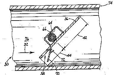
Referring now ~o FIGSo 3 and 4 a shaft 34 is
formed from two axially-extending components to accommodate
rigid securement of two spaced pinion gears 48, 50 to the
shaft, and to provide for installation of a tubular sleeve
52. The sleeve 52 surrounds a centrally-disposed, recessed
portion 54 of the shaft 34 and is freely rotatable there-
about via bearings 56. A plate 36 has ~wo rectangular
recesses (not shown) into which two rack gears 58, 60 are
15 -positioned and rigidly ~ecured to the plate. The plate 36
is provided with a ~uitable rim seal-(not shown~ and is
positioned parallel to the shaf~ 34`such that the latter
equally bisects the plate and the rack gears 58, 60 engage
the pinion gears 48, 50. To minimize binding, the gears 48,
50, 58,~60 and recesses are dimen~i.oned to ensure that the
: contac~ po~nts:between the gears are nominally flu~h with
the surface 62 of the plate 36. ~ generally C-shap~d
bracke~ 64 envelops the haft 34 and ~ welded at its ends
~ - to tha plate.36'....1-The bracket 64 is'dimenæioned;~o accom-
modate the expected ran~e of transl~tional movemènt of ~he
plate 36 relative to the shaft 34, and to ensure that its
: dis~al;inner~surface:66 abuts.the~ou~er ~urface of the
~- sleeve 52 . ? .: The:pla~e 36.has a.hole 68 formed therethrough.
A:reed, hinged--flap 7Q,--or functionally similar-gating
- ,:. 30 device;is;~sec~red~to thè.~plate 3S so that i~:eovers the
hole 68. ?The flap~70 and hole 68 cooperate~to form the
~ :~pilot valve ~38.~iThe pilot valve 38:.is-e~sentially;a-æecond-
ary eheck valve and unc~ion~ to effec~ a change in thP
,
.
w~ 6~ _ P~Tt~ O/~
,
--t7 -- . .
locatiun of the center o pressure 22 tFIG. 2) so ~hat the
check valve 30 opens when flow proeeeds in the desired
direc~ion 32. A stop 72 secured to the flap 70 limits
movemen~ so that the flap can close when flow proceeds in
the opposite direction 46. The shaft 3~t iS rigidly secured
to a duet 74 so tha~ it extends-transversely across an
elongate flow path 7~ which ~s de~ined by the duct, and does
not rotate about its axis 35 (FIG. 2~.
In operation~ when flow proceet~ in the desired
direction 32, pressure exerted by the fluid on the flap 70
causes ~he pilot valve 38 to open, thus permitting flow
through ~he pilot valve. This effectively moves the center
of pressure 22 above the pivot line 40 tFIG. 2 _ in the
illustrated embodiment the pivot line is defined by the
poin~s of con~act between-the rack and pinion gears 48, 50,
58, SO~. Consequently, the plate 36 rotates clockwi~e as
viewed in FIGS. 3 and 5.
~ . .
Since the axis of rotation of the plate 36 is
not coincident with the axis 35 ~FIG. 2) of the ~haft 34,
; 20- rotation is accompanied by revolutionary movement of the
.plate relatlve to the axis 35,.which in turn is accompanied
by tran~lational movement of the pla~e relative to the a~is
-.~ 35. In ffect,-this can bè viewed as a rolling motion of
- ~ .the plate 36 around the shaft 340 ^ . .-
25 ` r ~ In the.simplest form of the invention, the plate
~,~t~ '~ ', "` '-`! -' 36~would abu~-~he::sha~.34^along a pivot`line^40 ~FIG. 2)~- ~ extending acro~s..the plate. ~However,:it is desirable to
ensure;that for a:particular ~ngle~o rota~ion of thè plate
.~: . -36, there is a repeatablej p~rticular degrèe of transla-
~ 30 ~ional movement of the pla~e relative to the shaft 34.
.: . . ~.
.
.. . . . - . .. ~ . - ..
~r o ~
~ i ilJii4h3 ~ ''`. n~ P(~ lX~ l X2
--7--
Accordingly, the illustrated embodiment incorporates mechan-
ical timing means in ~he form o rack and pinion gears 48,
50, 58, 60 which prevent slippage between the plate 36 and
the shaft 34. As an alternative to the illustrated timing
means, one could employ an arrangement in which three strips
of a flexible material are wound around the shaft 34 and
suitably secured to both the shaft and the plate 36. Two
outer strips would be wound in one direction and a central
strip would be wound in an opposl~e direction. Such an
arrangement would be similar in operation to that of a
reel-type window shade.
Returning now ~o the operation of the check valve
30 and referring to FIGS. 2 9 3, 4, and 5, as the pla~e 36
rotates clockwise the teeth of the rack gears 58, 50 sequen-
~ially engage the teeth of the pinion gears 48, 50, thuspreventing slippage as the pivot line 40 moves clockwise
around the stationary shaft 34 and dow~ward along the plate
36. The area 42 above the pivot line 40 increases with
increasing angles of rotation 45 until an angle is reached
at which the center of pressure 22 i~ again aligned with ~he
pivot line 40.. A test.has demons~rated that for a plate 36
with no protrusion ~such as the flap 70), a "fully
-. open" angle of rotation 45 of slightly less than ninety
- .. degrees:can be achieved.-~
.. , . . ~ . . . . . .. . .
~-- ;25.~ ,;.The-effect of.the flap J0 on the fully-open angle
ha~lnotJbeen determined. However,~a number of possibilities
- ~-are,contemplated,for either minimizing ~hi effect or pro- :
viding a particular fully-open anglP in a given design.
These include opening the flap 70 from the opposite side of
the hole 58 (i~e. as vie~ed in FIG. 5 the flap would open
downwardly instead of upwardly), appropriately dimensioning
the flap andtor the ~top 72; using a very thin reed instead
.. ~
W(~ 'Jl/~ill4~ PCr!l~S~n/fl:slX2
.
of the fl~p; and in applieations whPre thP plate 36 i6
sufficiently thickt securing the flap to the plat~ inside
the hole.
When flow proceeds in the opposite direction 46,
aerodynamic forces act to close the flap 70. The center of
pressure associated with these forces ~s 80 located
relative to the pivot line 40 that the closing torque
applied to the plate 36 is e~en greater than would ob~ain
if the pivot line were centered relative to the plate.
Consequently, the plate 36 is quickly rotated in a
counterclockwise direction, with the rack gears 58, 60
rolling around the pinion gears 48, 50, until it reache~
the closed position indicated by FIG. 3. -If the plate 36
transitorily overshoots the closed posi~ion, ~he lower area
44 is made transitorily greater ~han the upper area 42 and
the ~erodynamic forces act to return the plate~to the
closed position. Conversely~ if the plate 36 for any
reason transitorily rotates in a clockwise direc~ion while
flow is proceeding from right to left, the upper area 42 is
made transitorily greater than th~e lower area 44, and again
~the plate 36 i8 returned;to thei`closed position.:
. The reader shoult understand that the foregoing
text and accompanylng drawings.are not intended to restrict
the scope of the invention to specific details which are
25 ~ancillary to the teaching contained herein. Ar~ordingly,
the-invention ~hould~be construed as broadly i as ;'is con~
. te!~t wi~h the following claims`and-theiir equivalent~.
~, ~ r , ~ i ~ 7 ~ ro .~
. ' : ` , ~
. ` . . ~ `
:
,
.