Note: Descriptions are shown in the official language in which they were submitted.
2~8~
SPINAL FIXATCIR REDUCTION FRAME
TECHNICAL FIELD
The present invention relates to devices for
use in spinal fixation operations and more particularly
to a device for controlled alignment of a fractured spine
in conjunction wlth the Vermont Spinal Fixator implant.
BAC~GROUND OF 'rHE INVENTION
Although not part of the present invention, a
basic understanding of the Vermont Spinal Fixator is
important to the understanding of the present invention.
FIG. 1 illustrates one half of a Vermont Spinal Fixator
device 10 ln place on a spine, the same components are
also used on the opposite side of the spine and are not
shown. The fi~ator device is designed to rigidly fix
together two spinal vertebrae surrounding a fractured
vertebrae and, thus, fuse ~he spine around the fractured
vertebrae. The Vermont Spinal Fixator is disclosed in
detail in Krag et al., An Internal Fixator for Posterior
Application to Short Seaments of the Thoracic, Lumbar or
Lumbosacral Spine, Clinical Orthopaedics and Related
Research, 203: 75-98 (Feb. 1986).
In order to implant the fixator device 10,
holes are drilled in the appropriate vertebrae through
the pedicle on either side of each vertebrae. After the
holes are drilled, pedicle screws 12 are screwed into
place using a shaft handle 14 which is attached to flats
16 provided on the top of each screw 12. The shaft
handles 14 are best seen in FIG. 2. Once the pedicle
screws 12 are in place, each one has an articulating
clamp 18 attached to it by means of a clamp bolt 20.
Clamp bolt 20 is placed through clamp 18 and
loosely threaded into the head of pedicle screw 12. The
clamp bolts 20 are left loose until realignment of the
vertebrae by the reduction frame has been completed.
Shaft handles 14 remain attached to the tops of the
2s5
7 ~ ~
pedicle screws 12. The shaft handles may be provided
with removable grips which are not shown in FIG. 2.
As a result of various spinal disorders of the
type which the fixator device 10 is intended to remedy,
such as trauma, one vertebra is displaced to an abnormal
position relative to an adjacent v~rtebra. For this
reason the surgeon must manipulate the vertebrae back
into normal alignment before the clamp bolts 20 are
finally tightened and the spine is rigidly fixed in
position.
In the past, in order to place the spine in
proper alignment, the surgeon would either move the lower
half of the patient's body with respect to the upper
half, or would grasp the shaft handles 14 and use them as
separate levers to manipulate the spine.
These procedures have a number of
disad~antages. First, they not allow for fine control of
the alig~ment and force applied, and also require the
surgeon to hold the spine exactly in alignment while the
clamp bolts are tightened. Second, when the handles are
grasped and pushed together manually to produce
extension, a compressive force is also produced. This
compressive force is difficult to prevent manually and
can cause bone fragments to be pushed posteriorly against
the spinal cord. Third, while flexion and extension of
the spine are generally possible with this technique,
distraction (the in-line spreading apart of the spine)
and compression are difficult, if not impossible, to
achieve with accuracy and control. The difficulty arises
due to the fact that the shaft handles act as levers on
the spine, thereby tending to cause rotation of the
vertebrae, which may not be desired. Fourth, there is a
danger that excessive force may be applied to either the
right or left pedicle screw during the application of
force for accomplishment of realignment. This danger is
present because of the absence of a rigid linkage between
2~ 1'1'
-- 2~87~
the right and left pedicle screws to provide an automatic
balancing of forces.
There are a number of implants and reduction
frame type devices in the prior art. However, none of
them overcome the above disadvantages, at least without
creating other disadvantages. For example, U.S. patent
No. 3,865,105 to Lode discloses a device for exerting
force on and fixing the spinal column. The Lode device
appears to be designed primarily for the correction of
scoliosis. The arrangement of this device renders it
impractical for use in producing realignment of vertebrae
affected by fractures and dislocations. The amount of
control provided is limited as it is much less of a
factor in applications such as straightening an
unfractured spine contemplated by the Lode device. Also,
the three point attachment directly to the transverse
process or spinous process would obstruct the surgicai
area such that a spinal fixator device being implanted
could not be easily accessed.
U.S. patent Nos. 4,433,677; 4,658,809 and
4,854,304 all show spinal fixation devices which are
adjustable for distraction and compression. These all
exhibit the primary disadvantage of not allowing flexion-
extension adjustment which is often necessary for
alignment of various spinal disorders including fractures
and dislocations. These devices also generally employ
turnbuckle type adjustments which are difficult to use
under surgical conditions and do not offer significant
mechanical advantage.
SUMMARY OF THE INVENTION
It is therefore an object of the present
invention to provide a device for producing realignment
of vertebrae affected by various spinal disorders,
including fractures and dislocations, which device
employs a significant mechanical advantage.
2s5 1~1~
- 2~5~ 7~ ~
Another object of the present lnvention is to
provide such a device which may be attached to the spine
in any orientation prior to alignment.
Another object of the present invention is to
provide a device for alignment of the spine which does
not block access to the surgical area in order to allow
for access to the fixator deviee being implanted.
It is also an object of the present invention
to provide a device for alignment of a spine which
distributes the applied foree evenly across the screws
and pedieles to which it attaches.
Yet another object of the present invention is
to provide a versatile device which may be used with hand
application of forces and varying degrees of mechanical
assistance.
~ further object of the present invention is to
provide a device for alignment of a spine which is
capable of controlling all modes of motion, that is,
flexion/extension, lateral bending, axial rotation,
distrac~ion/compression, anterior/posterior shear, and
lateral shear.
A further object of the present lnvention is to
provide a device for alignment of a spine which includes
a mechanical means for producing the motions of
flexion/extension, distraction/compression, and
anterior/posterior shear.
These and other objects are achieved by a
reduction frame according to the present invention which
is secured by shaft clamp assemblies to shaft handles
extending from the pedicle screws of a fixator device.
The shaft clamp assemblies are provided with four degrees
of freedom ~3 rotational and l translational). The shaft
clamp assemblies secure two T-handles to the shaft
handles. Each T-handle may be grasped by hand to
manually apply forces to the spine, or the two T-handles
2S5 1'1'
2 ~ ~ 8 7 a~ rj
may be joined by a mechanically adjustable lower-rod
assembly.
The lower-rod assembly provides a mechanism to
produce controlled distraction/compression and provides a
fulcrum about which manually-applied force to the T-
handles will produce flexion/extension. The lower-rod
assembly is joined to each T-handle by means of a lower-
rod clamp, which is provided with 4 or 5 degrees of
freedom (2 or 3 rotational and 2 translational).
Each T-handle is provided with power screw
threads to allow for precise anterior/posterior
translational control. The shaft clamps and lower-rod
clamps are provided with taper fit joints to allow for
infinite rotational adjustment and fixture.
For further mechanical control, an upper-rod
assembly may also be attached to the T-handles as
desired. By rotating either nut on the upper-rod
assembly, the distance between the upper ends of the T-
handles may be increased or decreased. This will cause
the T-handle to rotate about its lower-rod clamp, thereby
rotating the vertebra to produce the desired alignment.
Finger grips are provided on the upper-rod assembly to
allow the surgeon to easily use one hand to either apply
or monitor the force acting along the upper-rod.
The reduction frame according to the present
invention allows for the controlled application of forces
to produce motion of one vertebra relative to another, by
means of attachment of the device to the pedicles. The
T-handles function as handles to allow manipulation of
the spine with an even distribution of force between
opposite pedicles, in order to prevent the application of
excessive load to either pedicle. The power screw
adjustments allow for a fine and gradual application of
force to produce the desired vertebral movements. The
multiple degrees of freedom of the clamps allow for
assembly of the reduction frame in any orientation and
255 . 1'1'
7 ~
for forces to be applied in virtually any direction. The
T-handles are offset from the surgical area by hinged
extensions to allow for easy access to the device
assembly device after alignment has been achieved, in
order to allow for final fixation and tightening of the
clamp bolts.
BRIEF DE8~RIPTION OF T!IE DRAWINGS
The features and advantages of the present
invention will be more readily apparent from the
following detailed description of the invention
illustrated in the drawing fig~res, wherein:
FIG. l is a side view of a spine with a Vermont
Spinal Fixator implanted thereon;
FIG. 2 is a side elevation of the reduction
frame according to the present invention;
FIG. 3 is a section view through line 3-3 of
FIG. 2;
FIG. 4 is a partial section view of a shaft
clamp of the present invention;
Z FIG. 5 is a perspective view of a T-handle of
the present invention; and
FIG. 6 is a perspective view of the lower-rod
assembly of the present invention.
DETAI~ED DESCRIPTION OF T~E ~NVENTION
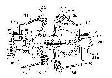
Referring to FIGS. 2 and 3 it can be seen that
the reduction frame 50 according to the present invention
comprises three basic assemblies: T-handles l00, of
which there are two; lower-rod assembly 200; and upper-
rod assembly 300. ~ne T-handle l00 is shown separately
in FIG. 5 and lower-rod assembly 200 is shown separately
in FIG. ~. It should be understood that the upper and
lower-rod assemblies are not necessarily required for the
proper functioning of the invention. As will become
apparent, depending on the degree of control desired by
2~87~
the surgeon, the T-handles 100 may be used alone, with
the lower-rod assembly 200 only, or with the upper and
lower-rod assemblies 300, 200.
Each T~handle 100 has a dorsally extending
threaded leg 110 and two laterally extending arms 112.
S Threaded leg 110 is provided with power screw threads
114. A sleeve 116 is placed over the dorsally extendiny
leg 110 and its dorsal-ventral location is controlled by
thumb nuts 118. The leg 110 may be provided with a flat
side 120 cooperating with a complimentary flat inside
sleeve 116 to prevent undesired rotation of the sleeve
116. Disposed on sleeve 116 are female clamping collar
117 and eye socket 119. Female clamping collar 117 is
rotatable around sleeve 116. Clamping collar 117 may be
fixed against rotation by tightening screw 115, shown
best in FIG. 3. The function of the sleeve 116 is
related to the lower-rod assembly 200 and therefore will
be discussed below in conjunction with that component.
Eye socket 119 receives ball nuts 316 of upper-rod
assembly 300.
Disposed adjacent the outer extremity of each
laterally extending arm 112 is a shaft clamp 122. The
shaft clamps provide a positive linkage between the T-
handles 100 and the shaft handles 14 attached to the
pedicle screws 12. The orientation of the shaft handles
14 extending Erom the pedicle is dependent llpon the
orientation oE the vertebrae prior to alignment.
Therefore, it must be possible to attach the T-handles
100 to the shaft handles 14 in any orientation. For
this reason the shaft clamps 122 provide for three
rotational degrees of freedom and one translational
degree of freedom along shaft handles 14.
In order to allow for further flexibility in
positioning the T-handles 100 and, in particular, to
provide greater access to the surgical area after ~he
reduction frame has been installed on the spine, the
255 1'1'
- ~`587~
--8--
laterally extending arms 112 of the T-handles 100 have
hinged extensions 136. Thus, in a preferred embodiment
of the present invention, the shaft clamps 122 are
disposed at the end of the hinged extensions 136 of the
laterally extending arms 112.
Shaft clamps 122, shown in detail in FIG. 4,
comprise two U-shaped collars 124, 126 which are
clamped together by a bolt 128 and retained by internal
threads 129 in collar 126. A retaining ring 127 may be
provided on bolt 128 to prevent the bolt from backing out
l of collar 126. Internal taper fit joint 130 is provided
between the two collars 124, 126 of a shaft clamp 122 in
order to allow for infinite positioning and positive
fixation. To create the taper fit joint 130, collar 126
is formed with frustoconical projection 132 and collar
126 with a mating frustoconical recess 134 of slightly
smaller dimension. Tightening of bolt 128 increases the
interference fit and provides positive fixation.
Loosening of bolt 128 allows slippage between the mating
frustoconical parts 132, 134 which may then be placed in
an infinite number of positions because the mating
surfaces are smooth.
The T-handles 100 of the present invention
provide a positive linkage between the two pedicles to
which it is attached. The linkage ensures that force
applied is evenly distributed to the two pedicles,
thereby decreasing the likelihood of damage to any one
pedicle. Once the T-handles 100 have been installed as
described above, they may be used by the surgeon simply
as handles for manual manipulation of the spine without
assembling further components of the present invention.
Such a procedure might be appropriate when only minor
adjustments of the spine are required.
If the nature of the misalignment is such that
it can not be easily or safely accomplished manually with
3 only the T-handles 100, then the lower-rod assembly 200
255 1'1'
7 ~
may be installed. Lower-rod assembly 200, shown
separately in FIG. 6, comprises a rigid lower threaded
rod 210 of sufficient length to extend between and beyond
the dorsally extending legs 110 of the T-handles 100 when
they are installed on the spine in their usual
configuration. Power screw threads 212 are also used
for threaded rod 210. Placed over and slidable on
threaded rod 210 are lower-rod sleeves 214 and 215.
Translation and fixation of the lower-rod sleeves on
threaded rod 210 are controlled by thumb nuts 216.
Threaded rod 210 is also preferably provided with a flat
side 218 engaging a complimentary flat inside the lower-
rod sleeves to prevent undesired rotation.
Lower-rod sleeve 214 is linked to one of the
T-handle sleeves 116 by male clamping collar 220 which
cooperates with an associated female clamping collar 117.
Female clamping collar 117 has a frustoconical recess
117a which mates with a frustoconical projection of male
clamping collar 220 to provide a frustoconical taper fit
joint similar to taper fit joints 130 in shaft clamps
122. Tightening of the taper fit joint between collars
117 and 220 is accomplished by bolt 221.
Flat side 218 on rod 210 prevents relative
rotation between collars 214 and 215. Therefore, to
allow opposite T-handles 100 to be angled with respect to
each other when lower-rod assembly 200 is utilized, male
clamping collar 220 is free to rotate around sleeve 214.
The rotation is controlled by screw 222 which causes male
clamping collar 220 to tighten on sleeve 214.
Lower-rod sleeve 215 is linked to the opposite
T-handle 100 by male member 224 which is formed
integrally with sleeve 215. Male member 224 also has a
frustoconical projection which is received in
frustoconical recess 117a of the associated female
clamping collar 117. Bolt 226 controls the tightening of
255 1'1'
7 ~ ~9
--10--
the taper fit joint formed between male member 224 and
female clamping collar 117.
The arrangement of lower-rod assembly 200
effectively provides for rigid connection between T-
handles loo and lower-rod assembly 200, while providing
five degrees of freedom for adjustment: two rotational
degrees of freedom provided by clamping collars 117
around sleeves 116 and around their taper fit joints with
clamping collars 220, 224; one rotational degree of
freedom provided by male clamping collar 220 and sleeve
214; and two translational degrees of freedom provided by
the movement of T-handle sleeves 116 or threaded leg 110
and lower-rod sleeves 214 and 215 on threaded rod 210.
With the lower-rod assembly 200 installed on
the T-handles 100, the surgeon may execute any of the
common movements of the spine (flexion, extension,
distraction, compression or anterior/posterior shear)
with a high degree of mechanical control. For example,
1.3 all rotational degrees of freedom may be fixed and only
translation along lower-rod assembly 200 utilized. This
would provide a pure distraction-compression movement.
The movement can be controlled with great precision by
the use of thumb nuts 216. Alternatively, all degrees of
freedom may be fixed except for one rotational degree of
freedom between T-handles 100 and lower-rod assembly 200
about a transverse or side-to-side axis. This would
provide a pure flexion-extension movement by force
applied manually to the dorsally extending legs 110 of
the T-handles 100. It should be readily appreciated that
by employing the various adjustments available with the
reduction frame according to the present invention, an
infinite variety of controlled compound movements may be
devised as required to align the fractured spine.
Even greater mechanical control may be achieved
by the additional use of upper-rod assembly 300. The
upper-rod assembly 300 comprises a threaded rod 310 of
~SS 1'1'
2~587~3
--11--
a~out the same length as the lower threaded rod 210,
although it may be relatively smaller in diameter because
it experiences only tensile and compressive forces. The
threads 312 on the upper-rod assembly 300 are again
preferably power screw threads. The upper-rod 310 runs
through eye sockets 119 on T-handle sleeves 116 and ball
nuts 316 bear against the eyes 119 to apply force to the
T-handles 100. Finger grips 318 may be provided on the
upper-rod 310 to provide a means for the surgeon to feel
the amount of force required for a particular movement.
To do so, the surgeon places T-handle sleeve 116 in his
palm and then wraps his fingers around finger grip 318,
whereby a squeezing motion gradually applies an inward
force to the ends of the T-handles 100 (moving the
handles together). The use of ball nuts 316 allows for
fine mechanical control of movements such as the flexion-
extension movement described in the preceding paragraph.
The invention has been described above with
reference to the Vermont Spinal Fixator device shown in
FIG. 1. However, with only minor modifications depending
on the particular clevice, the invention may be utilized
with any spinal fixation device which employs at least
four points of attachment to the spine, similar to the
Vermont Spinal Fixator. Such modifications are well
within the ability of a person of ordinary skill ln the
~5 art based on the disclosure contained herein.
Illustrative examples of such devices are contained in
the followincJ publications: W. Dick, The "fixateur
interne" As a Versatile ImPlant for Spine Surqerv, Spine
12:882-900, 1987; Olerud et al., Transpedicular Fixation
of Thoracolumbar Vertebral Fractures, Clinical
Orthopaedics and Related Research 227:44-51, 1988; and
Guyer et al., The Wiltse Pedicle Screw Fixation System,
Orthopaedics 11:1455-1460, 1988.
The detailed description of the invention
contained herein is intended to in no way limit the scope
2SS 1'1'
- 2~587~
-12-
of the invention. As will be apparent to a person
skilled in the art, various modifications and adaptations
of the structure above described will become readily
apparent without departure from the spirit and scope of
the invention, the scope of which is defined in the
appended claims.
255 1'1'