Note: Descriptions are shown in the official language in which they were submitted.
~~~9~~ 6
MULTI-ROLLER ELECTROSTATIC TONING
BACKGROUND AND SU1~KARY OF THE INVENTION
There are a number of advantages associated
with non-magnetic and non-conductive toner, if it
can be utilized instead of magnetic and conductive
toner. Many present electrostatic imaging
technologies, such as the present ion deposition
printing (MIDAX) technology, presently use magnetic
and conductive toner, and therefore are limited in
color and print quality, and the toners are
relatively expensive. Non-magnetic and
non-conductive toners are available in a wide
variety of colors, are available in a smaller
particle size (which enhances print quality), and
are generally less expensive than existing magnetic
and conductive toners. Also, non-magnetic toner
images placed on a printed page are advantageous in
security printing applications, and will not
interfere with magnetically scanned characters on
the same area of a printed document.
There have been a number of proposals for
utilizing lower conductivity and magnetic strength,
or non-magnetic and non-conductive, toners, such as
shown in U.S. Patent 4,777,106. One method, which
has been recognized to effectively utilize such
toners, is to have the toner maintained in a
fluidized condition and electrostatically charge the
toner in the fluidized state. However, prior art
techniques for maintaining the fluidized bed of
powdered toner have not been entirely successful,
and additionally prior art systems for transferring
2
63423-358
the fluidized toner to an image cylinder or the like have been
restricted in scope. For example, some such proposals are truly
useful only for application to an image cylinder at or about the
six o'clock position and do not control wrong polarity or low
charged toner. However, there is a need, in order to develop a
practical system, to apply toner to an image cylinder at or above
the nine o'clock position, provide high toner transfer
efficiencies, and to control wrong polarity and low charge toner
in order to maintain a clean background image.
According to the present invention a method and
apparatus are provided which accomplish the above mentioned
goals. The basic apparatus according to the invention for apply-
ing a non-magnetic and non-conductive toner to a member containing
an electrostatic pattern (typically a rotating image cylinder)
comprises the following elements: a container having a closed
bottom and sides, for containing powdered toner; means for
fluidizing the toner in the container; means for simultaneously
stirring and electrically charging the powdered toner in the
container; and means for transferring toner from the container to
the member containing an electrostatic pattern. The
simultaneous stirring and electrically charging means preferably
comprises a plurality of rotating elements having radially
outwardly extending sharp appendages (e. g. blades) mounted within
the container, and charged to a high voltage, e.g. at least about
7kv (e.g. +8kv), causing a coronal or atmospheric breakdown of
the fluidizing gases and depositing electrical charge on the
surface of the toner particles in the bed. This
~05~0~~
3
means, although illustrated to work in the positive
polarity mode (e. g. + 8 kv) and imparting a positive
polarity charge on the toner, is not restricted to
the positive mode only. By reversing the polarity
of the rotating elements, it has been found equal
performance is achieved with a negative driving
potential. (The means for transferring toner to the
image cylinder -- e.g. the rollers --- are also run
in opposite polarities to those described herein and
performance is equal.) The means for running in
either polarity described provides a means to
control the toner to run in either polarity which
makes the powder (toner) used material independent.
That is to say, material and surface additives used
to generate a specific triboelectric charging means
is independent of this described electrostatic
coronal charging process.
The fluidizing means preferably comprises a gas
pervious false bottom of the container, with air
being introduced between a solid bottom and the
false bottom to flow upwardly into the container.
Also, the fluidizing means preferably comprises an
electrical vibrator mounted to one closed side wall
of the container.
The powdered toner supply in the container is
automatically replenished whenever it drops below a
desired amount. This is accomplished utilizing an
optical sensing means which senses the level of the
toner, and controls a slotted roller mounted at the
bottom of the hopper (which has downwardly sloping
side walls) to discharge more toner into the open
top of the container.
CA 02059036 2000-11-21
63423-368
4
The means for transferring the toner from the
container to the image cylinder preferably comprises a
plurality of rotating conductive metallic cylinders mounted for
rotation about generally horizontal, parallel axes, and means
for electrically charging the cylinders. Preferably three
cylinders are provided, a first cylinder having a peripheral
surface thereof mounted just above the level of toner in the
container at an open top portion thereof, a second cylinder
having the axis thereof: mounted above the axis of rotation of
the cylinder and for removal of opposite sign charged toner and
low charge toner from t:he last cylinder, and a last cylinder
having the axis of rotation thereof mounted below the axis of
rotation of the first cylinder, and having the peripheral
surface thereof adjacent: both the peripheral surface of the
first cylinder, and the' image cylinder. Scrapers are
preferably associated with the first and last cylinders for
scraping unused toner therefrom to fall back into the container
through the open top thereof.
Thus, according to another aspect of the present
invention, there is prc>vided an apparatus for applying powdered
non-magnetic and non-cc>nductive toner to a member containing an
electrostatic pattern, comprising: (a) a container having a
closed bottom and side;, for containing powdered non-magnetic
and non-conductive powdered toner; (b) means for electrically
charging the powdered toner in the container; and (c) means for
transferring powdered toner from the container to a member
containing an electrostatic pattern, said means comprising: a
plurality of conductive: metallic rotating cylinders mounted for
rotation about generally horizontal, parallel, axes, having the
peripheral surfaces thereof spaced from said container; and
means for electrically charging said cylinders.
CA 02059036 2000-11-21
63423-368
4a
According to another aspect of the present invention,
there is provided an apparatus for applying powdered toner to a
member containing an electrostatic pattern, comprising: (a) a
container having a closed bottom and sides, for containing
'i powdered toner; (b) means for fluidizing the toner in the
container; (c) means for electsrically charging the powdered
toner in the container; (d) means for transferring toner from
the container to a member containing an electrostatic pattern;
and (e) means for replenishing the toner supply in said
1() container when it drops below a desired amount, comprising: an
open top of said container; a hopper located above said open
top; and sensing means for sensing the level of toner in said
container, and controlling said hopper to release powdered
toner into said container when the level is below the desired
1!~ amount .
According to another aspect of the present invention,
there is provided an apparatus for applying powdered toner to a
member containing an electrostatic pattern, comprising: (a) a
container for containing powdered toner having a closed bottom
2~) and sides, said closed bottom comprising an air pervious false
bottom which engages toner, and a solid bottom disposed below
said false bottom; (b) means for fluidizing the toner in the
container, comprising means for directing gas into the powdered
toner within the container between the solid and false bottoms,
2.'~ then through said gas pervious bottom; (c) means for
electrically charging th.e powdered toner in the container; and
(d) means for transferring toner :from the container to a member
containing an electrostatic pattern.
According to another aspect of the present invention,
3J a method of applying non-conductive and non-magnetic toner to a
member having an electrostatic pattern is provided, comprising
CA 02059036 2000-11-21
63423-368
4b
the steps of: (a) supplying powdered non-conductive and non-
magnetic toner to a container having a closed bottom, closed
sides, and open top; (~>) simultaneously stirring and
electrically charging t:he powdered toner in the container; (c)
maintaining the powdered toner in the container fluid; and (d)
5
2o~~o~s
transferring charged toner from the container to a
member having an electrostatic pattern thereon.
According to yet another aspect of the present
invention, a method of applying non-conductive and
non-magnetic toner to a member having an
electrostatic pattern comprising an image cylinder
rotating about a generally horizontal axis, having a
peripheral portion thereof exposed at or above a
nine o'clock position, comprises the following
steps: (a) supplying powdered non-conductive and
non-magnetic toner to a container having a closed
bottom, closed sides, and open top; (b) electrically
charging the powdered toner in the container; (c)
maintaining the powdered toner in the container
fluid; and (d) transferring charged toner from the
container to the exposed, approximately nine o'clock
positioned, peripheral portion of the image cylinder.
It is a primary object of the present invention
to provide an effective method and apparatus for
application of non-magnetic and non-conductive toner
to a member containing an electrostatic pattern,
such as an image cylinder. This and other objects
of the invention will become clear from an
inspection of the detailed description of the
invention, and from the appended claims.
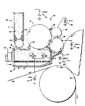
BRIEF DESCRIPTION OF THE DRAWING
FIGURE 1 is a schematic side view, partly in
cross section and partly in elevation, of exemplary
apparatus according to the present invention.
~~590~6
DETAILED DESCRIPTION OF THE DRAWING
FIGURE 1 illustrates an exemplary apparatus for
applying non-magnetic and non-conductive toner to a
member containing an electrostatic pattern. The
major components of the system of FIGURE 1
comprise: the container 10 and its associated
components, a hopper 20, a toner transfer means 30,
and an image cylinder 41 and associated components.
The container 10 has a solid bottom and closed
la side walls, and an air pervious false bottom 13.
Fluidizing gas, such as air, is introduced into the
container through the opening 11 into the chamber 12
between the solid bottom and the false bottom 13 so
that the gas flows upwardly through the air pervious
false bottom 13 into the powdered non-conductive and
non-magnetic toner 16 within the container. Also
within the container are a plurality of rotating
elements 14 having radially extending sharply
pointed appendages (e. g. blades) which are connected
up to a high voltage electrical source 15, e.g. an
electrical source of greater than about 7kv, in
particular an +8kv source in the exemplary
embodiment illustrated. The elements 14 comprise
means for simultaneously stirring and electrically
charging the powdered toner 16 within the container.
It has been found that the rotary motion of the
appendages 14 helps to uniformly stir and distribute
the toner and furthermore they improve the
uniformity of electrical charge and the rate of
electrical charging within the bed. It was found by
experimentation that the rotating coronal points are
far superior on these presented points when compared
~0~9~3~
to a single stationary coronal wire or an array of
stationary coronal points.
The mechanism of charging is related to the
coronal action or gas breakdown and ionization due
to the electrical field at the coronal points. This
driving mechanism deposits a charge on the surface
of the toner articles. Through experiment, it has
been determined that the potential voltage resident
on the surface of the fluidized bed matches that of
applied potential of the driving elements 14. The
polarity of the charge on the toner also matches
that of the polarity of the potential applied to the
driving elements.
Independence of toner polarity is a significant
advantage. Most toners are material sensitive, that
is, to achieve a specific polarity electric charge,
material composition and surface charging agents are
added so that specific polarity needed is achieved
when the toner triboelectrically charges itself
during frictional encounters with other toners,
stirring elements, developer material, etc. Through
experiment, it has been found that within the
fluidized electrostatic bed that toner polarity is
material independent -- that the means for charging
places the needed polarity charge on the toner
particles. Operation of the remainder of the system
components would simply revert to running in an
opposite sign (e. g. - the rollers and electrostatic
image on the imaging cylinder).
The air pervious false bottom 13 may be made of
any suitable pervious material, for example, a five
micron passage Porex polyethylene porous material,
8
~0~90~6
or a submicron diffuser made of at least a single
layer of porous stainless steel.
Eluidization of the powder 16 is also
accomplished by vibrating means. The vibrating
means preferably comprises a conventional electric
vibrator 18 which is mounted on one of the closed
side walls of the container 10, e.g. just above the
air introduction passage 11 for~fluidizing gas.
It is desirable to automatically replenish the
supply of toner powder 16 within the container 10
once it drops below a desired level. It is
important that there be proper transfer of toner
from the container 10 to the transfer system 3.0, and
therefore the level of toner must be relatively
carefully maintained. Preferably a sensing means --
such as an optical sensor -- is provided to
facilitate this level maintenance function.
The hopper 20, having straight side walls 21
with powdered non-conductive and non-magnetic toner
22 cantained therein, cooperates with the optical
sensor 19 to resupply the container 10 with toner.
This is preferably accomplished by utilizing a
slotted roller 23 rotatable about a generally
horizontal axis, and mounted at the bottom of the
side walls 21, preferably below the sloping side
wall portions 24 which facilitate feeding of the
powdered toner from the hopper 21 to the slots in
the roller 23. The slotted roller 23 supplies a
measured amount of toner into the container 10 for
each rotation, or each partial rotation.
The transfer means 30 preferably comprises a
first metallic conductive cylinder 3l~having a
scraper 32 associated therewith, a metallic
9
2o5~~~s
conductive applicator cylinder 33 having a scraper
34 associated therewith, and a second metallic
conductive cylinder 35 having a scraper 36
associated therewith. The sources of electrical
potential 37, 38, and 39 charge the cylinders 31,
35, and 33, respectively. All of the cylinders 31,
33, 35 are mounted for rotation about generally
horizontal axes, the axis of the cylinder 35
preferably being slightly above the axis of the
cylinder 31, and almost directly above the axis of
the cylinder 33, while the axis of the cylinder 33
is preferably below the axis of the cylinder 31.
The cylinder 31 is mounted so that its peripheral
surface is just barely above the level of toner 16
within the container 10, and the cylinder 33 is
mounted so that its periphery is adjacent both the
periphery of the cylinder 31 and the dielectric
coated image cylinder 41.
The roller systems 30 enable toner to be
applied to a dielectric coated image cylinder 41 at
about a nine o'clock position of the image cylinder
41 -- near the three o'clock position of the
cylinder 33. Note that the cylinder 33 rotates in a
direction of rotation opposite that of both the
cylinders 31 and 41. Cylinders 31, 33 and 35 are
all driven at speed such that the surface velocities
are all matched and either noted or are slightly
overdriven above that of the image cylinder 41. The
cylinder system 30 also has excellent control over
wrong polarity and the low charge toners and
excellent level control is possible because of the
gap transfers between the cylinders.
r
10
209036
During operation, the electrical potential
developed on the top of the fluidized bed surface of
toner 16 sets up an electrical field with the toner
first (feed) 31. The first cylinder 31 is biased to
about +450 volts by the power supply 37. Even
though the toner at the surface of the bed is
positively charged, a mass of violent migration of
the positive toner occurs to coat cylinder 31 as it
rotates in front of the bed surface. The field
established between the bed and the cylinder 31 is
about 2.5 million (2.5 x 10⁶) volts per meter, so
that migration of the charged toner is extremely
fast. Residual toner on the cylinder 31 is
continuously scraped back into the bed through the
open top thereof by the scraper 32. It has been
found that toner layer uniformity is best achieved
by presenting a clean cylinder surface to the field
present above the electrostatic fluidized bed, hence
all residual toner is totally removed by scraper 32.
At the gap between the first cylinder 31 and
the last, applicator, cylinder 33, toner is
transferred by the electrical field set up by the
potentials 37 and 39 (the preferred potential 39
being about -20 volts). Means are also provided for
adjustment of this potential to create necessary
electrical fields between the applicator 33 and the
electrostatic images on the image cylinder 41 to
achieve the necessary threshold levels to produce
good quality high contrast images (image to
background ratios).
The transfer of toner between transfer cylinder
31 and applicator roller 33 arid also between
applicator roller 33 and image cylinder 41 may be
11 2Q~90~~
enhanced also by providing a low frequency (1000 hz)
A.C. bias in addition to the existing D.C. potential
39 to help overcome the electrostatic adhesion force
of the toner to the roller. The field between the
cylinders 31, 33 is about 2 x 10⁶ volts per meter,
and toner "jumps" to cylinder 33 with a transfer
efficiency of greater than about 85%.
At the gap between the applicatar cylinder 33
and the image cylinder 41, toner is transferred to
image areas (the image cylinder 41 has an
electrostatic pattern thereon) which have
approximately a -300 volt surface potential. Once
again, the field between the cylinders 33, 41 is
about 2.OE06 volts per meter. Untransferred and
residual toner is returned to the container 10
through the open top by the scraper blade 34.
Applicator cylinder 33 may also be a resilient
coated member with a conductive coating on the
periphery, and still biased by potential source 39.
Such a cylinder would then be held in light contact
with image cylinder 41 and transfer of the charged
toner would still be effected by the field between
applicator cylinder 33 and the electrostatic image
on imaging cylinder 41. The cylinders 31, 33 are
entirely cleaned on each rotation. Transfer and
toner density can be controlled by varying the
electrical fields found between the cylinders by
controlling the potential on the fluidized bed
through high voltage electrical source 15, ar by
controlling the potential, on roller 31, by
adjusting potential 37, or on roller 33 by adjusting
potential 39.
12
205~4~~~
To control toner dust vectoring and prevent
clumped toner from dropping to the paper 23b 43, a
metallic conductive shield 44, which is biased to
about +150 V by potential 45, is mounted to the
front of the container.
The control cylinder 35 has the function of
removing opposite polarity toner and low charge to
mass ratio toner from the cylinder 33. At the gap
between the cylinders 35, 33 a very high field
(4.5E06 volts per meter) is set up by the potential
source 38 of about +1500 volts. This attracts any
existing negatively charged toner particles and also
induces a negative charge on any low charge
particles on the cylinder 33. These toner particles
are removed from the control cylinder 35 by the
scraper blade 36, and/or are vacuumed off (vacuum
not shown).
It will thus be seen that the apparatus
illustrated in FIGURE 1 can be used f_or a method of
, applying non-conductive and non-magnetic toner to an
image cylinder 41. The steps are supplying powdered
non-conductive and non-magnetic toner 16 to the
container 10; simultaneously stirring and
electrically charging the powdered toner in the
container 10 with the bladed, charged rotating
elements 14; maintaining the powdered toner in the
container 10 in fluid condition by introducing gas
through the porous false bottom 13, and vibrating
the container 10 utilizing the vibrator 18; and
transferring charged toner from the container 10 to
the image cylinder 41 utilizing the transfer system
30. Toner particles jump from the container 10 to
the periphery of the cylinder 31, then jump from the
13
20590~~
cylinder 31 to the applicator cylinder 33, and
ultimately from the cylinder 33 to the image
cylinder 41. From the image cylinder 41, the toner
is applied onto the paper web 43 on the transfer
cylinder 42 at the nip point between the cylinders
41, 42. The method also is practiced to apply the
toner to the portion of the image cylinder 41 that
is approximately at the nine o'clock position, the
cylinder 33 applying the toner at approximately the
three o'clock position thereof.
zt will thus be seen that according to the
present invention an advantageous method and
apparatus have been provided for applying
non-magnetic and non-conductive toner to a member
I5 containing non-electrostatic pattern. While the
invention has been herein shown and described in
what is presently conceived to be the most practical
and preferred embodiment thereof, it will be
apparent to those of ordinary skill in the art that
many modifications may be made thereof within the
scope of the invention, which scope is to be
accorded the broadest interpretation of the appended
claims so as to encompass all equivalent apparatus
and methods.