Note: Descriptions are shown in the official language in which they were submitted.
2 ~
CARD OPERATED ~OC~
This invention relates to a card operated lock, that is
a lock in wh~ch the key is i~ the form o~ a card which
carries a code for unlocking the lock. Such 'card keys'
are typically ~emi-rigid, substantially flat and formed
of cardboard, plastics and/or metal. The code may be in
various forms and typically may aomprise a pattern of
holes which i~ detected electronically in the lock, or a
pattern of magnetic poles such as described in
lo VS-A-4133194.
To assist handicapped persons, a lever operated lock is
specified in many applications. A lever is used to
unlatch the lock, but a separate key is still provided
to unlock the lock. This is particularly suitable with
a card operated lock where the card is inserted into the
lockset to unlock the lock, the card being retained in
the lock and the same hand being used to turn the lever
to withdraw the latch and open the door, after which the
card can be withdrawn and the lock returns to the locked
20 mode. Such a lock is described in EP-A-0241323.
To assist handicapped persons, the elderly and children
with the use of keys which compri~e a stem and a bow
(head) on thQ ~tem, the bow has been enlarged, or
elongated to form a T or ~ ~hape, which thus offers
better leverage and i~ easier to grasp, squeeze and
rotate when unlocking the lock. The key is turned to
throw a bolt or latoh, or otherwise to unlock ths lock.
Thus in ~ome lock~èts the key i~ turnad to allow the
bolt or latoh to be withdrawn by turning a lever-type
handle, and in others the turning of the key itself
will withdraw a bolt or latch.
A lever-type lockset is often more expensive than the
cylindrical type lock~et, such as is desaribed in
US-A-4133194, in which the lever is replaaed by a
15 cylindrical knob which is turned to withdraw the latch.
This is because a greater force can be applied to the
lever to try and force the lock, and a strong
spring-return mechani~m must be provided ~o return and
hold the lever in the horizontal position. Typically
the lever will be of steel or brass, except in very
light duty applications where it may be of aluminium,
which is more easily damaged. The cylindrical lockset
is, however, more difficult for the handicapped, elderly
and very young to operate ~ecause of the aombined
grasping and turning motion which is required. It i5
2~3~
also known to modify a cylindrical lockset by attaching
a lever to the knob. HoweverJ this is cumbersome, there
is often a problem with the spring return on the knob
not bsîng sufficient to counter the weight of the lever,
and also there i 8 ~till a need or a key to unlock the
lock.
A first aspect of the present invention provides a card
operated lock comprising a lockset having a
knob which i6 arranged to be turned to withdraw a
lo locking member, and a key in the form of a card which is
inserted into a slot in the knob to unlock the lock, a
free end of the card extending out of the knob whsn the
card is inserted in the knob to unlock the lock, whe.rein
the free end of the card is adapted to be operated on by
the user to turn the knob to withdraw the locking member.
The free end of the aard may be adapted by providing a
card of increased length which protrudes sufficiently
far out of the knob to be gripped or for the user to
bear on the card end, similar to the operation of a
lever. In another form, a T-bar or loop may he attached
to the free end of the card, the user gripping or
bearing on the T-bar or loop to pull on the end of the
card to rotate the knob.
2 ~ 3 ~
Very preferably the slot is arranged ao that the card is
inserted generally horizontally i~to the knob so that it
extenas out sideways fro~ the knob for optimum leverage
when a downwar~s forae is applled to the end o the
card. Preferably the slot will ~ace away from the
adjacent door jamb.
Other arrangement6 may be provided. For sxample the
card may be L-shapea to facilitate application of a
downwards force when the card is inssrted vertically
into a 810t, although such an arrangement provides for a
lar~er card key.
Another aspeat of the invention provides a aard operated
7Ock aomprising a lockset having a cylindriaal knob
which is arranged to w;thdraw a latah, and a key in the
form of a card which is inserted into a slot in the knob
to unloak the lock, wherein the slot is positioned
sideways of the knob for the card to be inserted
generally horizontally into the slot, and the knob :is - -
rotatable cloakwise and anti-clockwise, rotation in
either direction serving to withdraw the latah. In this
way, the lockset i5 completely reversible on a door.
The lockset may be positioned on the left or right of
the door, with the slot always ~acing the hinged side of
the door. As is usual, a bevelled latch i5 provided
which is reversible to suit the direction of opening of
the door.
Typiaally a lock6et will have a cylindrical/ card
operated lock on one end of the lookset spindle, and a
cylinder or lever direatly couplsd to the other end o~
the spindle. Where a second aylinder i6 used, it may be
provided with a ~lot to receive a card key for
lever-type operation, although the lock mechanism per se
is not needed (unless the opening of the door i8 to be
lo controlled by a key from both ~ides)~
third a~pect of the invention providss a card key for
a card operated lockset, the key being in~erted into a
510t in the lockset to unloak the lock, wherein the key
is adapted to be operated on by the user to perform an
unlatching operation of the lockset.
Preferably the key is adapted by providing a card of
increased length, and~or by providing a deviae on the
end of the card which can be readily gripped or engaged
by a handicapped or elderly person.
In operation, a separate handle or lever operated latch
is usually provided for moving the door open so that the
end of the card key itself will not be pushed or pulled
to open the door.
2 ~ 3 ~
The aspects of the invention are especially suitable for
use in magnetic key operated locks, such as described
in, inter alia, EP~A-0024242 ana US-A-4133194.
Other aspects, preferred features, and advantages of the
invention will be apparent from the following
~escription and the accompanying claims.
The i.nvention will be further described by way of
example with reference to the acoompanying drawing~, in
which:
Figure 1 is a perspective view of a lockset forming
an embodiment of the invention;
Figure 2 is an snd view of the lockset of Figure 1;
Figure 3 is a view on llne III-III of Figure 1; and
Figure 4 is a cross-sectional part view on line
I~-IV of Figure 2.
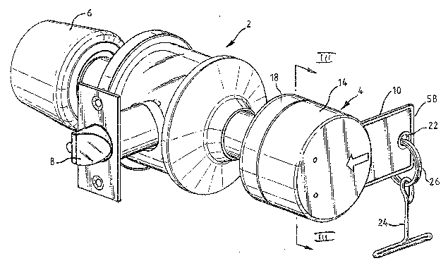
Figure 1 is a perspective view of an entrance-type
lockset 2 form.ing an embodiment of the invention. The
lockset 2 comprises a card-opsrated cylindrical locking
knob 4, and a rear locking knob 6 which has a
turn-button (not shown) to lock and unlock a front
spindle 12 (Figure 3) and in so doing also knob 4.
~he knobs 4, 6 are rotated to withdraw a locking member
in the form of a latch 8.
The aonstruction and working of the locking knob 4 is as
described in EP-A-0024242, subject to modifications
which will be described hereinafter in relation to
Figures 3 and 4.
The lockset 2 functions as follows. When the
turn-button ~not shown) in the end of the knob 6 is
pu~hed in, it locks the front spindle 12 (Fig.3). A key
10 must be insertsd into the knob 4 in order to unlock
the lock, the key being retained in the lock in unlocked
io mode. This couples the knob 4 to a aentre tailpiece
driver 11 to be rotated to cause withdrawal of the latch
8. This operation will cause the push button in the
knob 6 to pop-out and leave the lock in the unlocked
mode until the push button on knob 6 is pushed in
again. The front spindle 12 is thus free to rotate. In
this situation the latch 8 can be r~tracted by rotating
the rear casing 18 of the locking knob 4. The rear
casing 18 is attached to a core 36 which is fixed to a
spindle 61eeve 9 which is coupled to the front spindle
12 to rotate it. Rotation of the rear casing 18 thus
rotates the front spindle 12 to retract the latch 8.
This requires grasping the rear casing 18.
If the button is pushed-in and rotated ninety degrees,
it does not pop-out on turning of the knob 6 or by use
2'~3~
of a key to unlock the lock, and ~o continued keyed
operation of the lock is required. ~his ~ystem of
cylindrical lockset operation i8 well-known, and the
operation o~ the knob 4 and rear casing 18 are
particularly described in EP-A-00~4242.
The knob 4 has ~ front cylindrical oasing 12 whioh
houses a magnetic key operated loaking mechani~m. In
such a mechanism, a plurality of magnet pins are carried
in a slide member which is moved by the key 10 to
1~ operate ths lock. ~he magnet pins extend out of the
slide membe.r and project through holes in a lockplate
which is fixsd in the body of the knob 4. When the
correct key i8 inserted the pins are repelled out of the
holes in the lock plate, into the sli~e member, and so
further insertion of the key moves the slide member to
an unlocking position at which point the key i~ retained
in the mechanism, allowing the key to be released ~y the
user while the lock remains in the unlocked mode. In
the embodiment des~ribed, the front outer caslng 14 of
knob 4 is then coup~ed to the centre tailpiece driver 11
so that the casing 14 can be turned to rotate the
tailpiece 11 to withdraw the latch 8 with the same hand
that inserted the key 10.
A meahanism to retain the key in the knob, holding the
3 ~ ~
lock in the unloaked mode while the knob is turned, is
described in detail in EP-A-0241323 at Figures 5 and 6
and its application to the cylindrical knob of
EP-A-00242g2 is briefly described below by re~erence to
Figure 4.
Referring to Figures 1 and 2, for the user to open the
look, i.e. withdraw the bolt 8, when the turn-butto~ i8
pushed in (i.e. the lock is locked), the user inserts
the magnetic card key 10 into a slot 16 which i~
lo positivned sideways of the outer casing 14~ the ksy 10
being inserted in the horizontal direction. If the key
has the correct code it unlocks the lock, retains the
lock in the unlocked mode and so couples the casing 14
to the tailpiece 11. The outer free end 20 of the key 10
i~ then pushed or pulled laterally ~f the direction of
insertion in the plane of rotation of the knob 4 to
rotate the Xnob 4f (clockwise in Figure 2,~ and so
withdraw th~ latch 8. To facilitate the operation of
pushing or pulling on the key end 20, the card 10 is
made somewhat longer than usual, and/or is povided with
a T-bow, hook, ring or other means which can be engaged
by the user by a finger, prosthesis, etc, to apply ,a
turning movement or downwards force to the key end 20.
In practice the key movement will usually be at right
2 ~
angles to its long axis A-A, and so a rotational force
is applied generally in the dixection of arrow B (Figure
2).
The key is adapted to be operat~d on to rotate the knob
4 by, or example, being o inareased length, of
increased rigidity and/or by having a manually grippable
member attached to the free end ~0. Shown in Figure~ 1
to 3 ls a T-bar 24 whiah i~ suspended from an eyelet 22
in the key end 20 by a ring 26. Ring 26 i~ dimensioned
to clear the corners of the end 20 of the key 10. The
~-bar may be a ring or other shape.
The key 10 is of increased length so that when inserted
fully in the knob 4 to unlock the lock, the key end 20
extends further out than usual, by about 1.Scm to
lS provide additional leverage for the T-bar 24. Where a
T-bar or the like i~ not provided, an extra long key, of
increased length about 4¢m i8 provided so that the user
can bear down ~ireatly on the free ~nd 20 of ths key, in
the direction of arrow C (Fig. 2).
Thus, preferably the key 20 extends out of the casing 14
by from about 1.5 to 6cm, and particularly on the
shorter key an additional means is provided for
operating on the key.
In some othsr applications the front casing 14 of the
knob 4 is arranged to be free-spinning when the key is
3 ~
not inserted, so that the lock cannot be forced by
turning the casing 14. The key of this invention can be
used to operate such locks, in a ~imilar manner to that
described herein.
In the preferred embodiment, the knob 4 is sprung so
that when rel~ased it returns to a position with the
810t 16 facing sidaway~, in line w~th and away from the
latch 8. The mechanism shown in Figure 3 provides two
functions, one is to return knob 4 so that the slot 16
lo faaes sideways, and the seaond is to limit the rotation
of the casing 14 relative to the front spindle 12, so
that the casing 14 can be freely turned ninety degrees,
after which further turning will rotate the spindle 12
to withdraw the latch 8 when the lock i8 not locked~
i e. the turn-but~on is not pushed in.
Referring to Figure 3, the outer casing 14 which carries
the lock mechanism (not shown) such as the slider and
lock plate, has a fixed annular plate 30 which ls
fastened to the casing 46 by screws 32. A rotatable
annular plate 34 is fixed to a core 36 which rotates in
the annular plate 30 and is fixed to a cylindrical
spindle sleeve 9. Core 36 is coupled to the rear casing
part 18 ~Fig. 1) by screws 38, and casing part 18 thus
rotates with the core 36 and applies turning force to
the spindle 12.
~ ~ F3 ~
12
The rotatable plate 34 has two shoulders 40, ~2 which
are positioned to abut a tongue 44 extending in the
axial direction out of the plane of the plate 30. ~hus,
when plate 30 rotates ninety degree~ clockwise, tongue
44 abuts shoulder 40 and when rotated :ninety degrees
counter-clockwise, tongue 44 abuts shoulder 42. When
the lock i~ unlocked, the outer casing part 14 can be
rotated ninety degrees (in sither dir~ction~ to bring
tongue 44 against a shoulder 40 or 42, and further
10 rotation then rotate~ the plate 34, and so spindle 12
will withdraw the latch 8. For the handicapped~ this
rotation can be effected by inserting a key 10 in the
usual way in slot 16. The key does not need to be
inserted fully into the slot 16 because the lock is not
15 loc~ed. ~owever, where the mechanism includes means for
holding the key in the 810t 16 la~ described below), it
i~ preferred to insert the key fully as this helps hol~
the key in as the key i8 levered on. Also, this will
couple the casing part 14 to the aentre tailpiece driver
20 11, which will withdraw the latch 8 on rotation of the
casing part through only ninety degrees.
It will be appreciated that when the lock is locked, the
spindle 12 will not rotate and so movement of the casing
14 is limited by the tongue 44 abutting the shoulders
25 40, 42. ~o withdraw the latch 8, the key 10 is inserted
-
13
fully to unlock the lock and so couple the casing part
14 to the tailpiece driver 11. Rotation of the casing
part 14, and hence tailpiece driver 11, through only
ninety degrees then serves to withdraw the latch 8.
A coil spring 46 extends twice around the core 36,
underneath tabs 48 on th~ rotatable plate 34, and its
ends SO, 52 are hookad around tongue 44 and a ~imilar
tongue 54 on plate 34. Thus, when plate 30 is rotated
clockwise as seen in Fig. 3 (by rotating casing 14) tab
iO 44 pulls end 50 to tighten the spring, which will return
the plate 30, and casing part 14 to its rest po~i.tion
(Figure 3) when the casing part 14 i8 released.
Similarly, counterclockwise rotation causes tab 44 to
pull end 52 to tighten the spring. Thu~, the spring 46
serves to orient the casing part 14 with the slot 16
facing siaeways.
Figure 4 shows a ~ross-sectional detail o the knob 4 to
illustrate the mechanism for holding the key in the lock
in the unlocking position. The mecanism is similar to
that seen in EP-A-0241323 at Figures 5 and 6, with minor
adaption to suit the cylindrical lock of the type seen
in EP-A-024282. As it is well known, a slide member 60
carries in blind bores tnot shown) a plurality of magnet
pins (not ~hown). The pins are attracted by a
2 ~
14
steel plate 62 so as to project through holes ~not
shown~ in a bra~s locking plate 64 and abut an
intermediate plate 66. ~he loaking plats 64 is fixed in
position in the ~ront casing part 14 and so the pin#
prevent movement of the slide member ~0 rslatl~ to the
locking plate, thus the lock is locXed. To unlock the
lock, the key 10 is inser~ed between the intermediat~
plate 66 and ~teel plats 62 whi~h moves back agai~t
plate spring 68. The key, having the correct code,
iO repels the magnet pins to the bottom of the blind bores
out of engagement in the holes in the locking plate 64.
The Xey 10 abuts at its inner end (not shown) a to~ on
the slide member and so further movement of the key
moves the slide member which effects an action of
unlocking the lock. In the embodiment shown, movement
of the slide member couples the front casing part 14 to
the tailpiece 11.
.
The slide member 60 is moved against the urging force of
a coil spring (not shown) which urges the slide~member
to the locking position. ~o facilitate operation of the
lock with one hand, a key hold in mechanism holds the
slide member in the unlocked position while the key is
fully inserted in the lock. The key 10, as it is
inserted, bears on a cam 70 which is pivotally mounted
on a side of the slide member 60. As the slide member
3 ~ ~
is moved to the unlocked position, a claw 72 on the cam
rides under a leg 74 of a leaf spring 76 which i8 fixed
to a stationary plastics guide 78 in the front casing
part 14. The claw 72 catohes on a foot 80 of the leg 74
and so holds the slide member 60 in the unlocking
position, against the urging force of a coil spring (not
shown). The ~orce o the coil spring, when the slide
member 60 is held in the unlocking position, tends to
~ create a pressing ~orce urging the cam 70 against the
key 10, thus tending to hold or maintain the key in
place, enhancing the similar pressing force applied to
the other side of the key by the plate spring 68. ~f
course, the key 10 ~an ba readily withdrawn despite this
surface pressure. When the key is removed from the
lock, ths cam 70 is free to pivot away from the leaf
spring 76, and so the claw 72 can disengage from the
foot 80 by passing under it, to allow the slide member
to mcve back to the locking position.
The lockset is reversible,i.e. it can be used on either
edge of a door, since casing 14 can be rotated in either
direction to withdraw the latch 8 (which itself is
reversible).
It will be noted that with the card key of the invention
the key can be used to withdraw the locking member, even
if the lock is not previously locked, the key acting as
16
a lever when it is inserted in the knob 4. Thus the
user need not concern hi~self with whether or not the
lockset is locked or to test it to determine if a ~ey is
required. A handicapped person would be instructed to
s always insert hi6 key in the lock
Various modifications will be made to suit the many
diff2rent lock requirements. The lo~king knob 4 might
not be sprung to return, when released, to its rest
position, with the slot 16 sideways, when operating a
bolt action where the position of the bolt is coupled to
the rotational position of the knob 4. Some locks will
require the knob 4 to be rotated through more than
ninety degrees to withdraw a latch or bolt. Where
greater rotation is required, a shorter key may be used
lS to avoid hitting the door jam~, or to avoid hitting a
nearby lever.
Where the ~ey must be inserted with a particular face
towardfi th~ user, a groove or peripheral rib 58, or
other means such as an axially offset hole or a missing
corner or embossed arrow is provided to identify the
orientation of the key to a blind or partially sighted
person, as well as a visible indicator such as a printed
arrow. For magnetic lock systems, a metal or plastics
key 10 may be used, the former ~eing descri~ed in
GB-A-1569017 and the latter in GB~A-1209934, the metal
key being more suitable for longer length ~eys.
2 ~
17
Generally the key will be of sufficient rigidity to
enable it to be used as a lever. Where a cardboard key,
in particular, is used it may be neaessary to reinforce
the key. Although the invention has been desaribed with
particular reference to a cylindrical lock, it can be
used with other locking device&, such as rim locks,
mortise locks, dead bolts, etc.
The knob slot 16 can be positioned at other locations
than sideways. The plate 34 is coupled to the core 36
by four tangs 35 which engage in xeaesses 37 in the core
36. The tangs 35 and recesses 37 are spaced at ninety
degree intervals and so the plate 34 may be relocated
through ninety degree intervals relative to the core
36. This in turn will move the rest positions of the
annular plate 30 and associated lock mechanism and
casing 14 through ninety degrees.
Also it will be appreciated that the degree of free
movement of the front casing part 14 relative to the
rear casing part 18 (governed by the position of
shoulders 40, 42) may be varied to provide greater or
less free movement.
It may be preferable to locate the slot 16 facing
downwards for an outsi~e door lock. The key 10 can
2~3~i~
18
still be in~erted and pushed or pulled through ninety
degrees to open the lock, and the downwar~ly facing
position may be easier for a small child or someone in a
wheelchair.
Various modifications may be made to the described
embodiment and it i6 desired to include all such
modifications as fall within the scope of the invention.