Language selection

Search

Patent 2059714 Summary

Third-party information liability

Some of the information on this Web page has been provided by external sources. The Government of Canada is not responsible for the accuracy, reliability or currency of the information supplied by external sources. Users wishing to rely upon this information should consult directly with the source of the information. Content provided by external sources is not subject to official languages, privacy and accessibility requirements.

Claims and Abstract availability

Any discrepancies in the text and image of the Claims and Abstract are due to differing posting times. Text of the Claims and Abstract are posted:

  • At the time the application is open to public inspection;
  • At the time of issue of the patent (grant).
(12) Patent: (11) CA 2059714
(54) English Title: COLLAPSIBLE SIGNALLING POST
(54) French Title: POTEAU D'AFFICHAGE FLEXIBLE
Status: Expired and beyond the Period of Reversal
Bibliographic Data
Abstracts

English Abstract


The novel collapsible signalling post is provided with
a weakened section characterized by an helical groove carved on
the periphery of a tubular member to be mounted between an
anchoring member and a rod member supporting a sign. The groove
provides a weakened section adapted to split open along a portion
thereof and upon bending caused by a lateral force exerted on the
signalling post, the two end portions of the tubular member
remain connected to each other by the unfolded spires formed
between the helicoidal thread.


French Abstract

Poteau de signalisation frangible innovateur avec section affaiblie caractérisée par une rainure hélicoïdale gravée sur la périphérie d'un élément tubulaire à monter entre un élément d'ancrage et une tige supportant un panneau. La rainure donne une section affaiblie adaptée pour s'ouvrir le long de celle-ci et, quand elle est pliée sous l'effet d'une force latérale s'exerçant sur le poteau de signalisation, les deux parties d'extrémité de l'élément tubulaire demeurent reliées l'une à l'autre par les spires déployées qui sont formées entre les pas du filet hélicoïdal.

Claims

Note: Claims are shown in the official language in which they were submitted.


The embodiments of the invention in which an exclusive
property or privilege is claimed are defined as follows:
1. A collapsible signalling post, comprising:
a lower ground-engaging anchoring member for securing the
signalling post into the ground;
an upper post member; and
an intermediate tubular member for interconnecting the lower
ground-engaging anchoring member and the upper post member, said
intermediate tubular member defining a weakened tubular wall
comprising:
groove means made in the tubular wall to split open
along at least a portion thereof upon bending of the
intermediate tubular member caused by a lateral force exerted
on the upper post member; and
link means defined in the tubular wall by the groove
means for maintaining the upper post member fastened to the
lower ground-engaging anchoring member when the groove
means splits open.
2. A collapsible signalling post as recited in claim 1, wherein:
said groove means comprises a generally helical groove made
in an outer surface of the tubular wall; and
said link means comprises a generally helical strip formed in
the tubular wall by said generally helical groove.
3. A collapsible signalling post as recited in claim 1, wherein
said lower ground-engaging anchoring member has at least two wing
plates radially projecting therefrom, said plates each having a tapered
shape forming a pointed end for digging into the ground.

4. A collapsible signalling post as recited in claim 1, wherein
the upper post member comprises a connector means for securing a
display column to said upper post member.
5. A collapsible signalling post as recited in claim 2, wherein:
said intermediate tubular member is made of mild steel and has
a thickness of about 1/8 inch; and
said groove has a deepness equal to about 2/3 said thickness.
6. A collapsible signalling post as recited in claim 5, wherein
the intermediate tubular member has a diameter of about 1 1/2 to 2 inches.
7. A collapsible signalling post comprising
an anchoring member adapted to be secured into the ground,
said anchoring member having an upwardly directed throat member;
a tubular member having a lower part, a middle part and an
upper part, said lower part being fixed to said throat member, said tubular
member extending upwardly from said anchoring member;
a rod member having a tubular lower end fixed to said upper
part of said tubular member, said rod member extending upwardly from
said tubular member;
said middle part having an helical groove carved on the
periphery of the middle part of the tubular member, said groove defining
a weakened section adapted to split open along a portion thereof upon
bending caused by a lateral force exerted on said rod member;
said groove defining helical whorls adapted to stretch away
upon splitting open of the groove, said whorls having a width sufficient for
maintaining the lower and the upper part of the tubular member securely
connected together after said lateral force has been exerted.

8. A collapsible signalling post as recited in claim 7, wherein
the width of each whorl has a minimum of about 3/8 inch.
9. A collapsible signalling post as recited in claim 8, wherein
the tubular member is secured inside the throat member of the anchoring
member and inside the tubular lower end of the rod member, the said
throat member being adjacent the tubular lower end of the rod member.
10. A collapsible signalling post as recited in claim 9,
comprising a resilient ring member mounted around said tubular member
between said anchoring member and said rod member whereby said ring
member is adapted to squeeze upon bending of said tubular member.
11. A collapsible signalling post as recited in claim 10,
comprising a flexible link having two ends longitudinally extending inside
said tubular member, said link being fixed at one end to said anchoring
member and releasably held to said upper part of said tubular member,
at the other end, said link having a length adapted to prevent said whorls
to stretch beyond a predetermined limit.
12. A collapsible signalling post as recited in claim 11, wherein
said link is a chain secured to an axle transversally fixed through said
throat member and to a releasable washer adapted to sit on the upper
part of said tubular member.
13. A collapsible signalling post as recited in claim 12, wherein
said anchoring member has at least two wing plates radially projecting
therefrom, said plates having a tapered shape forming a pointed end for
digging into the ground.

14. A collapsible signalling post as recited in claim 12, wherein
said rod member comprises a connecting member for securing a display
column.
15. A collapsible signalling post as recited in claim 8, wherein
said tubular member is made of mild steel and has a thickness of about
1/8 inch and a groove of about 2/3 said thickness.
16. A collapsible signalling post as recited in claim 15, wherein
the tubular member has a diameter of about 1 1/2 to 2 inches.

Description

Note: Descriptions are shown in the official language in which they were submitted.


2 0 5 9 7 1 4
TITLE OF THE INVENTION
COLLAPSIBLE SIGNALLING POST
5 BACKGROUND OF THE INVENTION
Field of the invention
The present invention relates to a post provided with a
10 weakened section adapted to collapse when hit sideways. The section
is particularly structured so as to retain the post to its anchor and
accordingly prevent surrounding persons from being hit by a projected
post or the recoil of the post.
Prior art
A search made by the inventor has failed to reveal
pertinent references. Flexible posts have been c.ontemplated to prevent
the breaking of posts when hit such as in U.S. patent NQ 5,029,783.
20 Flexible posts have a recoil effect which is eliminated by the present
invention.
SUMMARY OF THE INVENTION
More specifically, in accordance with the present
invention, there is provided a collapsible signalling post, comprising:

20597 14
a lower ground-engaging anchoring member for securing
the signalling post into the ground;
an upper post member; and
an intermediate tubular member for interconnecting the
5 lower ground-engaging anchoring member and the upper post member.
The intermediate tubular member defines a weakened tubular wall
comprlslng: .
groove means made in the tubular wall to split open
along at least a portion thereof upon bending of the
intermediate tubular member caused by a lateral force
exerted on the upper post member; and
link means defined in the tubular wall by the groove
means for maintaining the upper post member fastened
to the lower ground-engaging anchoring member when
the groove means splits open.
Also in accordance with the present invention, there is
provided a collapsible signalling post comprising
an anchoring member adapted to be secured into the
20 ground, this anchoring member having an upwardly directed throat
member;
a tubular member having a lower part, a middle part and
an upper part, the lower part being fixed to the throat member, and the
tubular member extending upwardly from the anchoring member; and
a rod member having a tubular lower end fixed to the
upper part of the tubular member, the rod member extending upwardly
fromthe tubularmember.

2 0 5 9 7 1 4
The middle part has an helical groove carved on the
periphery of the middle part of the tubular member, and the groove
defines a weakened section adapted to split open along a portion thereof
upon bending caused by a lateral force exerted on the rod member.
The groove defines helical whorls adapted to stretch
away upon splitting open of the groove, these whorls having a width
sufficient for maintaining the lower and the upper part of the tubular
member securely connected together after the lateral force has been
10 exerted.
According to the invention, the groove means or helical
groove not only provides a means for weakening the signaling post, but
also provides a link to prevent spreading apart of the two opposite parts
15 of the signalling post.
An added security device is provided to prevent the
anchoring member and the rod member from being completely
disconnected from each other. It consists of a flexible link connected to
20 both ends of the tubular member. The link has a length longer than the
length of the tubular member but is intended to refrain the tubular
member from stretching beyond a predetermined distance or from
breaking completely.
The objects, advantages and other features of the
present invention will become more apparent upon reading of the
following non restrictive description of a preferred embodiment thereof,

2 0 5 9 7 1 4
2 b
given by way of example only with reference to the accompanying
drawings.
BRIEF DESCRIPTION OF THE DRAWINGS
In the apended drawings:
Figure 1 is a side view of a signalling post according to
the invention shown in the cross-section of the ground where it is
1 0 inserted,
Figure 2 is a view similar to figure 1 showing the
signalling post after being hit by a car,
Figure 3 is an enlarged view of the encircled portion 3
shown in figure 2,
Figure 4 is a cross-sectional view taken along line 44
of figure 1,
-

2 0 5 97 ~ 4
--3--
Figure 5 is a perspective view of a resistently pliable
and unrecoilingly stretchable tubular member,
F igure 6 is a view of the tubu lar member shown in
figure 5 in a stretched condition,
Figure 7 is a cross-sectional view of encircled portion
7 of figure 5,
Figures 8 and 8a are two alternative embodiments of a
cross-sectional view along line 8-8 of figure 4.
DETAILED DESCRIPTION OF THE INVENTION
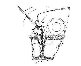
Figure 1 illustrates an anchoring member 10 secured
into the ground 11 and a rod member 12 supporting a sign 14. A
split sleeve 16 has an upper part 18 which is welded at 20 to the
rod member 12 and a lower part 22 which is secured to the
anchoring member 10. As shown in figure 2, the signalling post
shown in figure 1 is adapted to be collapsible when hit by a
lateral force such a car 24 pushing in the direction of the arrow
A. According to the invention, the rod member 12 will tilt in
the direction of the arrow B but remains connected to the
anchoring device 10 by means of a tubular member 26 of the type
illustrated in figure 5 .
The tubular member 26 has an upper part 28, a lower
part 30 and a middle part 32. The upper part 28 is located in
the throat of the upper part 18 of the sleeve 16 and secured
thereinto by a pair of fastening bolts 34. The lower part 30 of
the tubular member 26 is tightly secured into the lower part 19
of the sleeve 16 by a pair of tightening bolts 36.

20 5 97 ~ 4
--4--
As shown in cross-section in figure 4, the lower part
of the sleeve 26 rests on the upper part of the anchoring
device 10 and is fastened thereinto by the bolts 36. The upper
part 28 of the tubular member 26 which extends above the upper
edge of the lower part 19 of the sleeve 16 is covered by the
upper part 18 of the sleeve 16 and secured thereinto by the bolts
34. A ring 38 is preferably disposed between the lower edges of
part 18 and the upper edge of part 19. This ring is made of a
flexible material such as synthetic rubber. The ring 38 has a
rigidity to be able to support the rod member 12 but is
sufficiently flexible to squeeze when a very small amount of
lateral pressure in the direction of the arrow C is exerted on
the rod member 12, such pressure being within the modulus of
elasticity of the elements of the post under tension and
accordingly will permit the rod member 12 to return to its
original position in the direction of the arrow D. Such small
deflection will produce a contraction of the ring 38 as shown in
figure 2a.
The preferred embodiment of the tubular member 26 is
illustrated in figure 5 wherein the metal part has a helicoidal
groove which extends over, at least, a complete circumference of
the tubular member 26 and which, preferably, extends over about
five spires. For a hollow cylindrical tubular member having a
wall thickness of about 1/8 of an inch made of mild steel, a
groove having a depth about 2/3 of the thickness of the wall
provides a desired resistence to lateral blows produced by a car
hitting such a signalling post. A groove 40 having an angle of

20 5 97 ~ S
about 45 degrees allows the material of the tubular member to
bend without undesirable resistance. However, the width of the
strip between two spires is wide enough, i.e. a minimum of 3/8
inch to prevent separation of the upper part 28 from the lower
part 30.
When a solid blow is exerted on the rod member in the
direction of the arrow E (see f;gure 3), the middle part 32 will
be under such stress as to break along the weakened section, that
is, along the groove 40. If the pressure is maintained in the
direction of the arrow E, the spires 42 between the grooves 40
will stretch away while maintaining a connection between the
upper part 28 and the lower part 30 of the tubular member 26. As
shown in figure 2a, the tubular member 26 is resistently pliable
but becomes unrecoilably stretchable when it reaches the position
shown in figure 3.
As shown in figure 3a, the lower part 19 of the sleeve
16 may be made sufficiently short as to allow the car such as 24
shown in figure 2, to pass over the signalling post without being
hindered. In such a case, the upper part 18 of the sleeve 16 and
rod member 12 may stretch more extensively the middle part 32 of
the tubular member 26 in the direction of the arrow F.
If under certain unusual circumstances, the coil strip
32 is stretched beyond a predetermined limit, an additional
security link such as a chain 44 is provided to maintain the
connection between the upper part 18 and the lower part 19 of the
sleeve 16. The lower part of the chain 44 is retained at its

20 5 97 ~ 4
lower end to a bolt 46 passing across the lower part 19 of the
sleeve 16 and across the upper part of the anchoring member 10.
The upper part of the chain 44 is inserted through the aperture
of a washer 48 and held on the upper surface of the washer by a
bolt 50 which extends across the aperture in the washer 48. The
washer 48 has a dimension and more specifically a circumference
such as to rest on the top of the upper part 28 of the tubular
member 26.
The chain 44 is installed in its place before the rod
member 12 and in particular before the sleeve part 18 is secured
to the upper part 28 of the tubular member 26. The lower part of
the chain 44 is lowered inside the tubular member 26 before the
bolt 46 is inserted through the upper part of the anchoring
member 10. When the lowermost ring 52 of the chain 44 is at the
level of the apertures through which the bolt 46 extends, the
latter is passed across the ring 52. The bolt 46 is subsequently
held in place by the nut 54. Because the chain 44 can extend
much higher than the top edge of the upper part 28 of the tubular
member 26, it can be fixed as described above to the washer 48,
the latter being subsequently dropped over the upper edge of part
26. The length of the chain is predetermined so as to be longer
than the spires 42 when fully stretched. Accordingly, even when
the middle part 32 of the tubular member reaches its breaking
point, the rod member 12 will be retained to the anchoring member
and accordingly will not be projected and will not produce a
recoiling effect and accordingly will not produce any unintentio-
nal collision of the rod member with neighboring objects or

20597 14
--7--
persons.
The anchoring member 10 may be of the type disclosed by
in United States patent No. 5,010,698 on April 30, 1991 to the
present applicant. The anchoring device 10 is retained in the
ground by prongs 78 which are projected according to the above
mentioned patent and by fins which extend radially around the
core of the anchoring member 10. The fins 58 are downwardly
tapered to facilitate the penetration of the anchoring member in
the ground and their upper edge 60 are also downwardly tapered in
order not to interfere with the top surface 62 of the ground 11.
The tapering of the upper edges 60 is particularly useful when
the anchoring member is located in a hilly portion of the ground.
The number of fins 58 is preferably three which are evenly
disposed around the core of the anchoring member 10, that is,
~separated by 120 degrees from each other. A larger number of
fins has been found, in many circumstances, to divide the ground
into two small portion~s and accordinglv not provide the desired
gripping effect into the ground.
The novelty of the signaliing post which resides
especially in the resiliently pliable and unrecoilingly stret-
chable section of the tubular member 26 may be used to support of
variety of signs through different types of rod members. As
shown in figure 8, a square rod member is secured to the part 18
of the sleeve 16 depending on the municipal or the state
requuirements. Other types rod members such as U-shaped rod
member 64, as shown in figure 8a, can similarly be used in
connection with the present invention.

Representative Drawing
A single figure which represents the drawing illustrating the invention.
Administrative Status

2024-08-01:As part of the Next Generation Patents (NGP) transition, the Canadian Patents Database (CPD) now contains a more detailed Event History, which replicates the Event Log of our new back-office solution.

Please note that "Inactive:" events refers to events no longer in use in our new back-office solution.

For a clearer understanding of the status of the application/patent presented on this page, the site Disclaimer , as well as the definitions for Patent , Event History , Maintenance Fee  and Payment History  should be consulted.

Event History

Description Date
Inactive: IPC deactivated 2016-01-16
Inactive: IPC assigned 2016-01-01
Inactive: IPC expired 2016-01-01
Time Limit for Reversal Expired 2008-01-21
Inactive: Office letter 2007-02-28
Revocation of Agent Requirements Determined Compliant 2007-02-28
Appointment of Agent Requirements Determined Compliant 2007-02-28
Revocation of Agent Request 2007-02-06
Appointment of Agent Request 2007-02-06
Letter Sent 2007-01-22
Inactive: IPC from MCD 2006-03-11
Grant by Issuance 1998-08-04
Pre-grant 1998-03-31
Inactive: Final fee received 1998-03-31
Letter Sent 1997-10-07
Notice of Allowance is Issued 1997-10-07
Inactive: Application prosecuted on TS as of Log entry date 1997-10-01
Inactive: Status info is complete as of Log entry date 1997-10-01
Inactive: IPC assigned 1997-08-12
Inactive: IPC removed 1997-08-12
Inactive: First IPC assigned 1997-08-12
Inactive: Approved for allowance (AFA) 1997-08-07
All Requirements for Examination Determined Compliant 1994-01-25
Request for Examination Requirements Determined Compliant 1994-01-25
Application Published (Open to Public Inspection) 1992-07-29

Abandonment History

There is no abandonment history.

Maintenance Fee

The last payment was received on 1998-01-19

Note : If the full payment has not been received on or before the date indicated, a further fee may be required which may be one of the following

  • the reinstatement fee;
  • the late payment fee; or
  • additional fee to reverse deemed expiry.

Patent fees are adjusted on the 1st of January every year. The amounts above are the current amounts if received by December 31 of the current year.
Please refer to the CIPO Patent Fees web page to see all current fee amounts.

Fee History

Fee Type Anniversary Year Due Date Paid Date
MF (application, 6th anniv.) - small 06 1998-01-20 1998-01-19
Final fee - small 1998-03-31
MF (patent, 7th anniv.) - small 1999-01-20 1999-01-11
MF (patent, 8th anniv.) - small 2000-01-20 2000-01-06
MF (patent, 9th anniv.) - small 2001-01-22 2001-01-08
MF (patent, 10th anniv.) - small 2002-01-21 2002-01-08
MF (patent, 11th anniv.) - small 2003-01-20 2003-01-13
MF (patent, 12th anniv.) - small 2004-01-20 2004-01-20
MF (patent, 13th anniv.) - small 2005-01-20 2005-01-19
MF (patent, 14th anniv.) - small 2006-01-20 2006-01-19
Owners on Record

Note: Records showing the ownership history in alphabetical order.

Current Owners on Record
DENIS P. HUGRON
Past Owners on Record
None
Past Owners that do not appear in the "Owners on Record" listing will appear in other documentation within the application.
Documents

To view selected files, please enter reCAPTCHA code :


To view images, click a link in the Document Description column (Temporarily unavailable). To download the documents, select one or more checkboxes in the first column and then click the "Download Selected in PDF format (Zip Archive)" or the "Download Selected as Single PDF" button.

List of published and non-published patent-specific documents on the CPD .

If you have any difficulty accessing content, you can call the Client Service Centre at 1-866-997-1936 or send them an e-mail at CIPO Client Service Centre.

({010=All Documents, 020=As Filed, 030=As Open to Public Inspection, 040=At Issuance, 050=Examination, 060=Incoming Correspondence, 070=Miscellaneous, 080=Outgoing Correspondence, 090=Payment})


Document
Description 
Date
(yyyy-mm-dd) 
Number of pages   Size of Image (KB) 
Representative drawing 1998-07-20 1 16
Description 1994-02-04 7 201
Drawings 1994-02-04 3 178
Claims 1994-02-04 3 65
Abstract 1994-02-04 1 12
Description 1997-05-20 9 259
Claims 1997-05-20 4 120
Commissioner's Notice - Application Found Allowable 1997-10-06 1 164
Maintenance Fee Notice 2007-03-04 1 172
Fees 2003-01-12 1 37
Fees 2002-01-07 1 38
Correspondence 1998-03-30 1 40
Fees 1998-01-18 1 43
Fees 2001-01-07 1 36
Fees 2004-01-19 1 34
Fees 1999-01-10 1 44
Fees 2000-01-05 1 41
Fees 2005-01-18 1 32
Fees 2006-01-18 1 51
Correspondence 2007-02-05 2 49
Correspondence 2007-02-27 1 13
Correspondence 2007-02-27 1 18
Fees 1997-01-09 1 39
Fees 1996-01-11 1 37
Fees 1995-01-12 1 31
Fees 1994-01-19 1 37
Prosecution correspondence 1992-01-19 7 227
Correspondence related to formalities 1994-01-23 2 77
Correspondence related to formalities 1992-04-26 1 19
Prosecution correspondence 1994-01-24 1 24
Courtesy - Office Letter 1994-02-16 1 70
Courtesy - Office Letter 1994-02-21 1 64
Prosecution correspondence 1997-04-20 3 92
Examiner Requisition 1996-10-28 2 71