Note: Descriptions are shown in the official language in which they were submitted.
2059885
PAGING SYSTEM AND ITS OPERATING METHOD
BACKGROUND OF THE INVENTION
Field of the Invention
The present invention relates generally to a paging
system and its operating method, and more particularly to
a paging system with a message display unit.
Description of the Related Art
There has recently been a marked development in the
field of mobile radio communications service, and paging
systems is one of the representative areas of this field.
Paging systems provide the simple service of transmitting
messages only one way, and the number of subscribers per
radio wave is by far greater than for other systems
(e.g., automobile telephone systems). As a result, their
subscription fees are low and their use has spread
rapidly. However, pager systems have recently been
improved so as to operate not only the calling service
but also to display messages on the pager.
A paging system with a message display service
comprises at least a paging control unit connected to
a public telephone network, a transmitter connected to
the paging control unit and a plurality of pagers for
receiving the paging signal transmitted from the
transmitter. When a paging request call originates
through a public telephone network, the paging
control unit accepts the incoming call along with the
20598,~5
2 74570-4
subscriber's number and message data, converts the incoming call
into a paging signal including the address code of the pager and a
message signal referring to a subscriber file, which retains the
corresponding relation between the subscriber's number and an
address code for the pager, and transfers the converted paging
signal to the transmitter. The transmitter transmits the paging
signal in the form of radio waves. On the other hand, each pager
is provided with a receiving circuit tuned for its specific
address code selectively, a control unit to store a succeeding
message signal in a storage unit, and a display means to display
the message on a display unit (prior art document, Japanese Patent
No. 64097/1988, discloses the constitution of a pager with a
display function).
Although such a paging system is quite effective, it is
still somewhat inconvenient because it only affords one-way
service. Pager carriers often worry that some messages might not
be received. Paging systems used with message-displaying pagers
have the advantage that a plurality of callers may send messages
incorporating the callers' names so as to distinguish who sent the
messages, but the receiving parties tend to worry about the
possibility that some messages may remain unreceived without any
way to check for them.
SUMMARY OF THE INVENTION
In view of the foregoing problems of the prior art, an
object of the present invention is to eliminate the worry of pager
users that some messages might by chance not be received.
Another object of the present invention is to provide
more reliable service that can display any unreceived messages.
~A
20s~88~
3 74570-4
In order to achieve the above objects, the present
invention comprises a method of operating a paging system
comprising steps at its paging control unit to convert an incoming
call received through the public telephone network which includes
a subscriber's number and message data into a paging signal which
includes an address code and a message signal then the paging
signal is transmitted. Each pager having a message display
function receives its address code selectively, and stores the
message signal in a storage unit and display the message on a
display unit. The operation at the paging control unit further
comprises steps of storing a renewed value for the number of calls
for each subscriber's number and transfer the renewed value of the
serial number to the transmitter together with the message signal.
The operation at each pager further comprises steps to store the
received value of the serial number of called times included in
the paging signal for each reception and compares the value with
that of the last message signal so as to alert the user when the
difference between the above values is two or more.
According to the present invention, another method of
achieving the above objects includes an operation at the paging
control unit comprising further steps to store the message data in
addition to the serial number of the number of calls for each
subscriber's number, to judge whether an incoming paging request
call through a public telephone network is a normal paging request
call or a call requesting a repeat transmission and to transfer
the requested paging signal including the value of the serial
number for the number of calls and its message data to the
transmitter when the call is judged to be a call requesting a
~: ^
I~A
20s98,~ ~
4 74570-4
repeat transmission.
In order to accomplish the first object, the paging
system according to the present invention comprises a paging
control unit for converting an incoming paging request call
received through a public telephone network. The paging request
call includes the subscriber's number and message data. The
paging request is converted into a paging signal consisting of an
address code and message signal. A transmitter transmits the
paging signal. A plurality of pagers incorporates message
displays. Each pager has means for receiving the address code
selectively. A control unit in the pagers stores the message data
in its storage unit. A displays unit to display the message data
on a display. The paging control unit further provides message
counters for each subscriber's number, counting means to count the
message counter value for each called subscriber's number
corresponding to each incoming paging request call, and means to
generate a paging signal which includes the message counter value
in the message signal corresponding to the subscriber's number
called for transfer to the transmitter. Each pager provides a
judging means to judge whether the message reception is in order
by comparing the received message counter value with that of the
last message signal. A display means displays a message
indicating the omission of message reception when a message is
judged to have been omitted.
In order to accomplish the second object, the paging
control unit in the inventive paging system further comprises a
judging means to judge whether an incoming call is a normal paging
request call or a call requesting a repeat transmission. A
~A
2059885
74570-4
message data storage means stores message data included in the
incoming normal paging request call in a message data storage unit
of the called subscriber's number in accordance with the message
counter value. A paging signal is generated which include the
given message counter value and the message data stored in the
message data unit in accordance with the given message counter
value in the incoming call for transfer to the transmitter for
each call requesting repeat transmission.
BRIEF DESCRIPTION OF THE DRAWINGS
These and other objects of the present invention will
become apparent from the following description in conjunction with
the accompanying drawings, in which:
Figure 1 is a block diagram illustrating the general
structure of the paging system of the present invention;
Figure 2 is a functional block diagram illustrating a
paging system as an embodiment of the present invention;
Figures 3a-3c is a diagram illustrating specific signal
formats of paging signals by way of example, where Figure 3(a) is
an address signal format, and Figure 3(b), (c) are examples of
message signal format.
Figure 4 is a flowchart showing the operation of paging
control unit 1; and
Figure 5 is a flowchart showing the operation of pager
3.
DESCRIPTION OF THE PREFERRED EMBODIMENT
Referring to the accompanying drawings, a detailed
description will now be given of an embodiment of the present
invention.
1.' ~
~ A
6 2059885 74570-4
A paging system according to the invention generally
comprises, as shown in the Figure 1, a paging ~ontrol unit 53
which converts a subscriber's number and message data included in
an incoming paging request call into a paging signal which
includes the corresponding address code and
~A
~;
20~i9~8~
message signal referring to built-in subscriber file 51
which shows the relation between the subscriber's number
and address code of each pager, a transmitter 54 to
transmit the paging signal, and a plurality of pagers
having a message-display function, each of which receives
its own address code selectively, stores the message data
in its storage unit 65, and displays the message data on
its display unit 54, the paging control unit 53 further
comprising message counters 56 for each subscriber, a
counting means 57 to add ~'1" to the message counter value
for each call to a respective subscriber and a paging
signal generating means 58 to generate a paging signal
which includes the renewed message counter value to
transfer to the transmitter 54, and each pager 55 further
comprises a judging means 59 to detect the omission of a
reception by comparing the message counter value with
that of the last message signal and a display means 60 to
display a message indicating the omission of reception
and its message counter value when a missed reception is
detected. In order to pick up an omitted message, the
paging system comprises in the paging control unit 53 a
judging means 62 to judge whether an incoming call is a
normal paging request call or a call requesting a repeat
transmission, storing means 63 to store message data
of incoming calls in the message data storage unit 61
corresponding to the value of message counter 56 and
2059885
generating means 64 to send a paging signal which
includes the requested message counter value and
corresponding message data from the message data storage
unit for the request of repeat transmission.
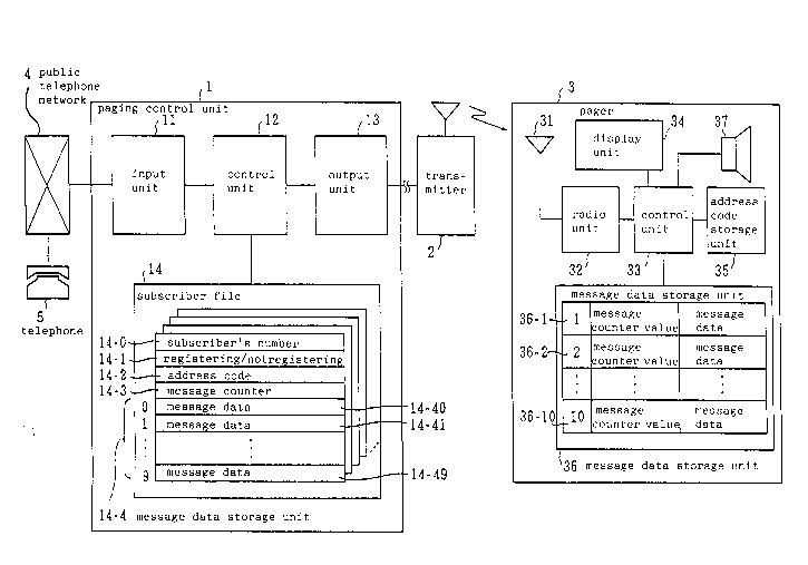
Fig. 2 is a block diagram illustrating a first
embodiment of a paging system to which a method of
operation according to the present invention is applied.
As shown in Fig. 2, a paging control unit 1 is
connected to a public telephone network 4 and accepts a
paging request call from a telephone 5. The paging
control unit 1 includes an input unit 11 for controlling
the connection with the public telephone network 4, a
control unit 12 for controlling the whole system, an
output unit 13 for producing a paging signal and connect-
ing the paging signal to a transmitter 2 and a subscriberfile 14. The subscriber file 14 stores all data that is
required for each subscriber in the paging control unit.
For example, the subscriber number 14 - 0; a mark indi-
cating registered/not registered 14 - 1, an address code
14 - 2 corresponding to the subscriber's number and a
message counter 14 - 3 are each stored in respective
areas, and a message data storage unit 14 - 4 is used to
store a plurality of message data. In this case, the
message counter 14 - 3 counts 0 up to 9 and returns to 0,
whereas the message data storage unit 14 - 4 has storage
areas 14 - 40 to 14 - 49 for a m~imum number of 10, each
20~988~
of which corresponds to the value of the message counter
14 - 3. The transmitter 2 is used for transmitting
paging signals transferred from the paging control unit 1
to a plurality of pagers 3 for receiving the paging
signal transmitted from the transmitter. Each pager 3
comprises an antenna 31, a radio unit 32, a control unit
33, a message display unit 34, an address code storage
unit 35, a message storage unit 36 having a plurality of
storage areas 36 - 1 to 36 - 10 for storing a plurality
of message data corresponding to the message counter
value 0 to 9 and an ~'alert~ generator 37.
A POCSAG signal is commonly used as the paging
signal (see CCIR Recommendation No. 584) and is also
employed in this embodiment. With respect to the
message, 4-bit rule numeric data is employed and the
first digit of a message signal (MSD) is used for the
message counter value. Fig. 3 shows an example of
specific signal formats: Fig. 3(a) shows an address
signal format, and Figs. 3(b) and 3(c) show message
signal formats. Fig. 3(b) shows an example of a message
signal format which includes the message counter value at
the first digit and message data in the remaining digits,
whereas Fig. 3(c) shows an example of a message signal
format for use successively when the message signal in
the format of Fig. 3(b) is insufficient.
Fig. 4 is a flowchart showing the operation of the
23~988~
paging control unit 1 and Fig. 5 is a flowchart showing
the operation of the pager. The operation of the
embodiment will now be described with reference to each
drawing.
The paging control unit 1 has an input unit 11 to
respond to incoming calls from any telephone (step 101),
and when a call is received, the paging control unit
starts the process of accepting a subscriber's number
(step 102). When the connection with the public tele-
phone network 4 is a direct trunk line, a multi-frequency
signaling can be used for sending the subscriber~s
number. Upon reception of the subscriber's number by the
input unit 11, the control unit 12 collates it with the
subscriber file (step 103). If the subscriber's number
is not registered (step 103), the control unit 12 causes
the generation an ineffective tone in order to inform the
caller that the call is an ineffective call (step 110)
and then terminates the call operation (step 111). When
the subscriber's number is verified as being registered
(step 103), the control unit further checks whether the
call is a call requesting a repeat transmission (step
104).
A call requesting repeat transmission is a call
from a pager carrier who wants to pick up an unreceived
message by the repeat transmission. In this embodiment,
a dual tone multi-frequency (DTMF) signal from a
20~885
push-button telephone is used to make calls requesting
repeat transmission by dialing a predetermined code, for
example "#*." Consequently, a caller is allowed to send
numeric data directly to make a normal paging request
call. Moreover, dialing a prearranged code, for example
## , will terminate the dialing of message data.
Assuming a caller makes a normal paging request call
(the operation for a call requesting repeat transmission
will be described later), the control unit 12 receives
the message (step 105) and deems the reception is over
when it receives the signal "##" (step 106). At the time
the call is completed, the control unit 12 adds "1" to
the message counter 14 - 3 corresponding to the called
subscriber's number (step 107) and records the received
message data in the storage area 14 - 4i corresponding
to the value (i) of the message counter 14 - 3 in
the message data storage unit 14 - 4 of the called
subscriber's number (step 108). The control unit 12
further sends the address code 14 - 2 registered at the
subscriber's number file, the value of the message
counter 14 - 3 and the received message data in the
storage area 14 - 4i to the output unit 13 (step 109).
The output unit 13 transfers the data received from
the control unit 12 as a paging signal to the transmitter
2, after encoding the address code for the format of Fig.
3(a) and the message counter value and the message data
2~9~85
12
for the formats of Fig. 3(b), 3(c). The transmitter 2
transmits the paging signal in the form of radio wave.
The pager 3 receives the paging signal via the
antenna 31 and the radio unit 32, and causes the control
unit 33 to check whether the address code conforms to its
own address code stored in the storage unit 35, that is,
to detect whether the pager has been called (step 201).
When the pager is called, the control unit 33 starts to
receive the message signal following the address code
(step 202) and stores the received data in the storage
area 36 - l in the message data storage unit 36 as a
message counter value and message data (step 203). In
this case, as message counter value and message data have
been stored in the message data storage unit 36 in the
lS serial order of reception, the control unit 33 compares
the message counter value received this time with that of
the last message signal in order to check whether there
is a gap in the message counter values (step 204).
Incidentally, "0" is processed as a continuous number
which follows 9" in the assignment of message counter
values. Nhen no gap is found between the message counter
values, the message data received this time is displayed
in the message display unit 34 and the "alert" generator
37 is caused to send an "alert" signal indicating recep-
tion of a call (step 205). If, however, there is a gapin the message counter values, the message display unit
20S988~
13
34 is caused to generate a specific alert (step 206) and
display a message to indicate the presence of an unre-
ceived message along with the omitted message counter
value in addition to the message data received this time.
With this operation, the pager carrier is informed of the
presence of an unreceived message as well as the message
counter value.
One method for storing the most recent message data
at the top position of the storage area 36 - 1 is to
transfer each message toward storage area having older
storage area numbers successively one by one at each
reception and erase the message in the storage area 36 -
10 at the following reception. Another method is to
provide registers Rl to R10 for holding addresses of
storage areas 36 - l to 36 - 10, respectively, and to
shift the contents of the register from R1 to R2, R2 to
R3, ..., R9 to R10, at each reception, so that the most
recent message is always stored in a storage area 36 - i
designated by the contents i of the register R1. At
the same time, the message in the storage area 36 - j
designated by the contents i of the register Rl0 is
successively erased.
A description will now be given of the operation of
picking up an unreceived message, that is, the operation
for a call requesting repeat transmission.
On confirming the presence of an unreceived message,
2~59~
14
a pager carrier dials his own subscriber's number through
any telephone as in the case of a normal call. The
paging control unit 1 performs processes up to Step 104
as for a normal paging request call. The pager carrier
dials "#*" from the push-button telephone to signal a
request for repeat transmission, and the control unit 12
of the paging control unit 1 judges the call to be a call
requesting repeat transmission (step 104) and anticipates
the reception of one digit representing the message
counter value of the missed call instead of message data
(step 112). When the pager carrier accordingly dials the
message counter value of the unreceived message displayed
on the pager 3 through the push-button telephone, the
paging control unit 1 receives it and the control unit 12
regards the acceptance of the message counter value as
the termination of the call requesting repeat transmis-
sion (step 113) and sends to the output unit 13 the
address code 14 - 2 registered at the called subscriber's
file, the message counter value, and the message data
stored in the storage unit 14 - 4 (Step 114).
The output unit 13 transfers the data received from
the control unit 12 as a paging signal to the transmitter
2 by encoding the address code for the format of Fig.
3(a), the message counter value, and the message data as
a message signal for the formats of Fig. 3(b), 3(c). The
transmitter 2 transmits the paging signal in the form of
2~i988~
radio wave. As a result, the unreceived message is
displayed on the message display unit 34 of the pager of
the pager carrier who has made the call requesting repeat
transmission. In other words, the operation of the pager
3 proceeds as normal from step 204 to step 206 in ~ig. 5
and the unreceived message is displayed at step 206.
Although a message indicating omission is also displayed
on the same image of display, the pager carrier can
determine that the displayed message is the one he
requested.
While the invention has been described with
reference to a preferred embodiment, the scope of the
invention is not limited to the particular form set
forth, but, on the contrary, can include such alterna-
tives, modifications, and equivalents as may be included
within the spirit and scope of the invention as defined
in the appended claims.